DESCRIPTION
|
Detection Item | Symptom |
Trouble Area |
|---|---|---|
| Front Camera Module Communication Stop Mode |
Any of the following conditions are met:
|
|
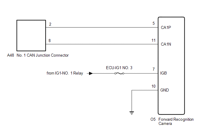
WIRING DIAGRAM
CAUTION / NOTICE / HINT
CAUTION:
When performing the confirmation driving pattern, obey all speed limits and traffic laws.
NOTICE:
Click here 
Click here
DTC check procedure: Turn the engine switch on (IG) and wait for 1 minute or more. Then operate the suspected malfunctioning system and drive the vehicle at 60 km/h (37 mph) or more for 5 minutes or more.
Click here
HINT:
PROCEDURE
|
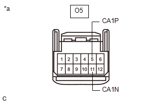
1. | CHECK FOR OPEN IN CAN BUS LINES (FORWARD RECOGNITION CAMERA BRANCH LINE) |
(a) Disconnect the cable from the negative (-) battery terminal.
(b) Disconnect the O5 forward recognition camera connector.
| (c) Measure the resistance according to the value(s) in the table below. Standard Resistance:
|
|
| NG |  | REPAIR OR REPLACE CAN BRANCH LINES OR CONNECTOR (FORWARD RECOGNITION CAMERA) |
|
| 2. |
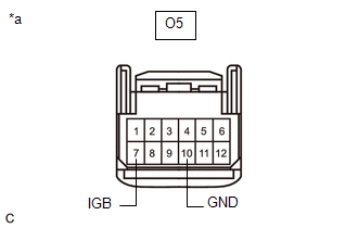
CHECK HARNESS AND CONNECTOR (POWER SOURCE CIRCUIT) |
| (a) Measure the resistance according to the value(s) in the table below. Standard Resistance:
|
|
(b) Reconnect the cable to the negative (-) battery terminal.
(c) Measure the voltage according to the value(s) in the table below.
Standard Voltage:
|
Tester Connection | Condition |
Specified Condition |
|---|---|---|
|
O5-7 (IGB) - Body ground |
Engine switch on (IG) |
11 to 14 V |
| OK | | REPLACE FORWARD RECOGNITION CAMERA |
| NG | | REPAIR OR REPLACE HARNESS OR CONNECTOR (POWER SOURCE CIRCUIT) |
DESCRIPTION
|
Detection Item | Symptom |
Trouble Area |
|---|---|---|
| Headlight ECU LH Communication Stop Mode |
Any of the following conditions are met:
|
|
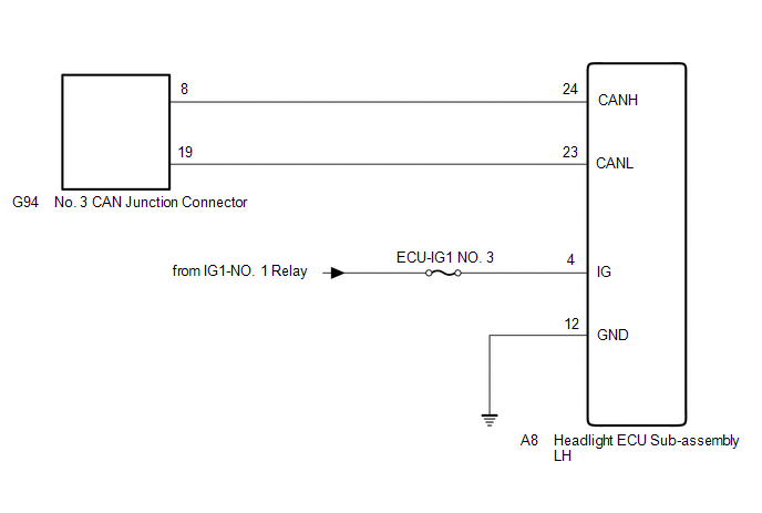
WIRING DIAGRAM
CAUTION / NOTICE / HINT
CAUTION:
When performing the confirmation driving pattern, obey all speed limits and traffic laws.
NOTICE:
Click here 
Click here
DTC check procedure: Turn the engine switch on (IG) and wait for 1 minute or more. Then operate the suspected malfunctioning system and drive the vehicle at 60 km/h (37 mph) or more for 5 minutes or more.
Click here
HINT:
PROCEDURE
|
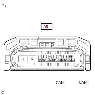
1. | CHECK FOR OPEN IN CAN BUS LINES (HEADLIGHT ECU SUB-ASSEMBLY LH BRANCH LINE) |
(a) Disconnect the cable from the negative (-) battery terminal.
(b) Disconnect the A8 headlight ECU sub-assembly LH connector.
| (c) Measure the resistance according to the value(s) in the table below. Standard Resistance:
|
|
| NG |  | REPAIR OR REPLACE CAN BRANCH LINES OR CONNECTOR (HEADLIGHT ECU SUB-ASSEMBLY LH) |
|
| 2. |
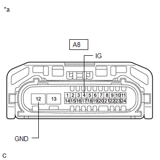
CHECK HARNESS AND CONNECTOR (POWER SOURCE CIRCUIT) |
| (a) Measure the resistance according to the value(s) in the table below. Standard Resistance:
|
|
(b) Reconnect the cable to the negative (-) battery terminal.
(c) Measure the voltage according to the value(s) in the table below.
Standard Voltage:
|
Tester Connection | Condition |
Specified Condition |
|---|---|---|
|
A8-4 (IG) - Body ground |
Engine switch on (IG) |
11 to 14 V |
| OK | | REPLACE HEADLIGHT ECU SUB-ASSEMBLY LH |
| NG | | REPAIR OR REPLACE HARNESS OR CONNECTOR (POWER SOURCE CIRCUIT) |
DESCRIPTION
|
Detection Item | Symptom |
Trouble Area |
|---|---|---|
| Headlight ECU RH Communication Stop Mode |
Any of the following conditions are met:
|
|
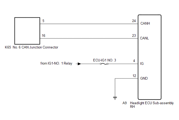
WIRING DIAGRAM
CAUTION / NOTICE / HINT
CAUTION:
When performing the confirmation driving pattern, obey all speed limits and traffic laws.
NOTICE:
Click here 
Click here
DTC check procedure: Turn the engine switch on (IG) and wait for 1 minute or more. Then operate the suspected malfunctioning system and drive the vehicle at 60 km/h (37 mph) or more for 5 minutes or more.
Click here
HINT:
PROCEDURE
|
1. | CHECK FOR OPEN IN CAN BUS LINES (HEADLIGHT ECU SUB-ASSEMBLY RH BRANCH LINE) |
(a) Disconnect the cable from the negative (-) battery terminal.
(b) Disconnect the A9 headlight ECU sub-assembly RH connector.
| (c) Measure the resistance according to the value(s) in the table below. Standard Resistance:
|
|
| NG |  | REPAIR OR REPLACE CAN BRANCH LINES OR CONNECTOR (HEADLIGHT ECU SUB-ASSEMBLY RH) |
|
| 2. |
CHECK HARNESS AND CONNECTOR (POWER SOURCE CIRCUIT) |
| (a) Measure the resistance according to the value(s) in the table below. Standard Resistance:
|
|
(b) Reconnect the cable to the negative (-) battery terminal.
(c) Measure the voltage according to the value(s) in the table below.
Standard Voltage:
|
Tester Connection | Condition |
Specified Condition |
|---|---|---|
|
A9-4 (IG) - Body ground |
Engine switch on (IG) |
11 to 14 V |
| OK | | REPLACE HEADLIGHT ECU SUB-ASSEMBLY RH |
| NG | | REPAIR OR REPLACE HARNESS OR CONNECTOR (POWER SOURCE CIRCUIT) |
Toyota Avalon (XX50) 2019-2022 Service & Repair Manual > Front Suspension: Front Shock Absorber
Components COMPONENTS ILLUSTRATION *A w/o AVS - - *1 FRONT SHOCK ABSORBER WITH COIL SPRING *2 FRONT SPEED SENSOR *3 FRONT STABILIZER LINK ASSEMBLY *4 FRONT FLEXIBLE HOSE *5 STEERING KNUCKLE - - Tightening torque for "Major areas involving basic vehicle performance such as moving/turning/stopping": N ...