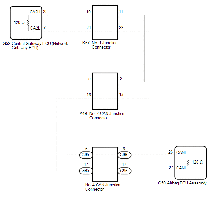
DESCRIPTION There may be an
open circuit in one of the CAN main bus lines when the resistance
between terminals 22 (CA2H) and 7 (CA2L) of the central gateway ECU
(network gateway ECU) is 70 Ω or higher. |
Symptom | Trouble Area | |
Resistance between terminals 22 (CA2H) and 7 (CA2L) of the central gateway ECU (network gateway ECU) is 70 Ω or higher. |
- CAN main bus lines or connector
- Central gateway ECU (network gateway ECU)
- Airbag ECU assembly
- No. 2 CAN junction connector
- No. 4 CAN junction connector
- No. 1 junction connector
| This malfunction is not related to the lines of a CAN branch or to ECUs or sensors connected to a CAN branch. WIRING DIAGRAM
 CAUTION / NOTICE / HINT
CAUTION: When performing the confirmation driving pattern, obey all speed limits and traffic laws.
NOTICE:
HINT:
- Before disconnecting related connectors for inspection, push in on each
connector body to check that the connector is not loose or disconnected.
- When a connector is disconnected, check that the terminals and connector body are not cracked, deformed or corroded.
PROCEDURE |
1. | CHECK FOR OPEN IN CAN MAIN BUS LINES (NO. 1 JUNCTION CONNECTOR) |
(a) Disconnect the cable from the negative (-) battery terminal. (b) Disconnect the K67 No. 1 junction connector.
(c) Measure the resistance according to the value(s) in the table below.
|
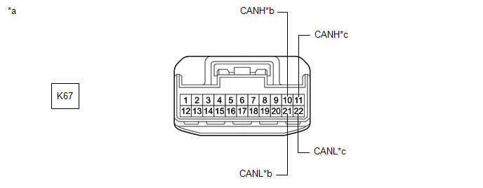
*a | Front view of wire harness connector
(to No. 1 Junction Connector) |
*b | to Central Gateway ECU (Network Gateway ECU) | |
*c | to No. 2 CAN Junction Connector |
- | - |
Standard Resistance: |
Tester Connection | Condition |
Specified Condition | Connected to | |
K67-10 (CANH) - K67-21 (CANL) |
Cable disconnected from negative (-) battery terminal |
108 to 132 Ω | Central gateway ECU (network gateway ECU) | |
K67-11 (CANH) - K67-22 (CANL) |
Cable disconnected from negative (-) battery terminal |
108 to 132 Ω | No. 2 CAN junction connector |
|
Result | Proceed to | |
OK | A | |
NG (Line to central gateway ECU (network gateway ECU)) |
B | | NG (Line to No. 2 CAN junction connector) |
C |
| A |
 | REPLACE NO. 1 JUNCTION CONNECTOR |
| C |
| GO TO STEP 3 |
|
B |
 | |
| 2. |
CHECK FOR OPEN IN CAN MAIN BUS LINES (CENTRAL GATEWAY ECU (NETWORK GATEWAY ECU) - NO. 1 JUNCTION CONNECTOR) |
(a) Reconnect the K67 No. 1 junction connector. (b) Disconnect the G52 central gateway ECU (network gateway ECU) connector.
| (c) Measure the resistance according to the value(s) in the table below.
Standard Resistance: |
Tester Connection | Condition |
Specified Condition | |
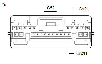
G52-22 (CA2H) - G52-7 (CA2L) |
Cable disconnected from negative (-) battery terminal |
108 to 132 Ω | |
 |
|
*a | Front view of wire harness connector
(to Central Gateway ECU (Network Gateway ECU)) | | |
| OK |
| REPLACE CENTRAL GATEWAY ECU (NETWORK GATEWAY ECU) |
| NG |
| REPAIR OR REPLACE CAN MAIN BUS LINES OR CONNECTOR (CENTRAL GATEWAY ECU (NETWORK GATEWAY ECU) - NO. 1 JUNCTION CONNECTOR) |
| 3. |
CHECK FOR OPEN IN CAN MAIN BUS LINES (NO. 2 CAN JUNCTION CONNECTOR) |
(a) Reconnect the K67 No. 1 junction connector. (b) Disconnect the A49 No. 2 CAN junction connector.
(c) Measure the resistance according to the value(s) in the table below.
|
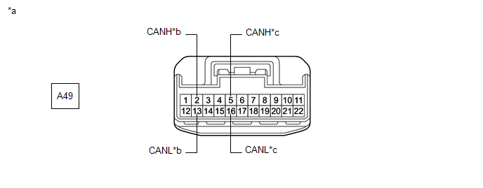
*a | Front view of wire harness connector
(to No. 2 CAN Junction Connector) |
*b | to No. 1 Junction Connector | |
*c | to No. 4 CAN Junction Connector |
- | - |
Standard Resistance: |
Tester Connection | Condition |
Specified Condition | Connected to | |
A49-2 (CANH) - A49-13 (CANL) |
Cable disconnected from negative (-) battery terminal |
108 to 132 Ω | No. 1 junction connector | |
A49-5 (CANH) - A49-16 (CANL) |
Cable disconnected from negative (-) battery terminal |
108 to 132 Ω | No. 4 CAN junction connector |
|
Result | Proceed to | |
OK | A | |
NG (Line to No. 1 junction connector) |
B | | NG (Line to No. 4 CAN junction connector) |
C |
| A |
| REPLACE NO. 2 CAN JUNCTION CONNECTOR |
| B |
| REPAIR OR REPLACE CAN MAIN BUS LINES OR CONNECTOR (NO. 2 CAN JUNCTION CONNECTOR - NO. 1 JUNCTION CONNECTOR) |
|
C | |
| |
| 4. |
CHECK FOR OPEN IN CAN MAIN BUS LINES (NO. 4 CAN JUNCTION CONNECTOR - NO. 2 CAN JUNCTION CONNECTOR) |
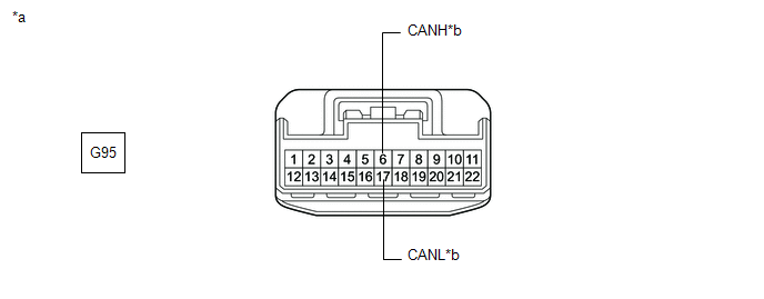
(a) Reconnect the A49 No. 2 CAN junction connector. (b) Disconnect the G95 No. 4 CAN junction connector.
(c) Measure the resistance according to the value(s) in the table below.
|
*a | Front view of wire harness connector
(to No. 4 CAN Junction Connector) |
*b | to No. 2 CAN Junction Connector |
Standard Resistance: |
Tester Connection | Condition |
Specified Condition | |
G95-6 (CANH) - G95-17 (CANL) |
Cable disconnected from negative (-) battery terminal |
108 to 132 Ω |
| NG |
| REPAIR OR REPLACE CAN MAIN BUS LINES OR CONNECTOR (NO. 4 CAN JUNCTION CONNECTOR - NO. 2 CAN JUNCTION CONNECTOR) |
|
OK | |
| |
| 5. |
CHECK FOR OPEN IN CAN MAIN BUS LINES (NO. 4 CAN JUNCTION CONNECTOR) |
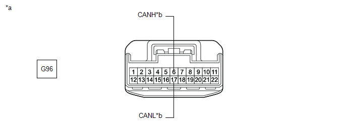
(a) Reconnect the G95 No. 4 CAN junction connector. (b) Disconnect the G96 No. 4 CAN junction connector.
(c) Measure the resistance according to the value(s) in the table below.
|
*a | Front view of wire harness connector
(to No. 4 CAN Junction Connector) |
*b | to Airbag ECU Assembly |
Standard Resistance: |
Tester Connection | Condition |
Specified Condition | |
G96-6 (CANH) - G96-17 (CANL) |
Cable disconnected from negative (-) battery terminal |
108 to 132 Ω |
| OK |
| REPLACE NO. 4 CAN JUNCTION CONNECTOR |
|
NG | |
| |
| 6. |
CHECK FOR OPEN IN CAN MAIN BUS LINES (AIRBAG ECU ASSEMBLY - NO. 4 CAN JUNCTION CONNECTOR) |
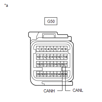
(a) Reconnect the G96 No. 4 CAN junction connector. (b) Disconnect the G50 airbag ECU assembly connector.
| (c) Measure the resistance according to the value(s) in the table below.
Standard Resistance: |
Tester Connection | Condition |
Specified Condition | |
G50-26 (CANH) - G50-27 (CANL) |
Cable disconnected from negative (-) battery terminal |
108 to 132 Ω | |
 |
|
*a | Front view of wire harness connector
(to Airbag ECU Assembly) | | |
| OK |
| REPLACE AIRBAG ECU ASSEMBLY |
| NG |
| REPAIR OR REPLACE CAN MAIN BUS LINES OR CONNECTOR (AIRBAG ECU ASSEMBLY - NO. 4 CAN JUNCTION CONNECTOR) | | 


