DESCRIPTION
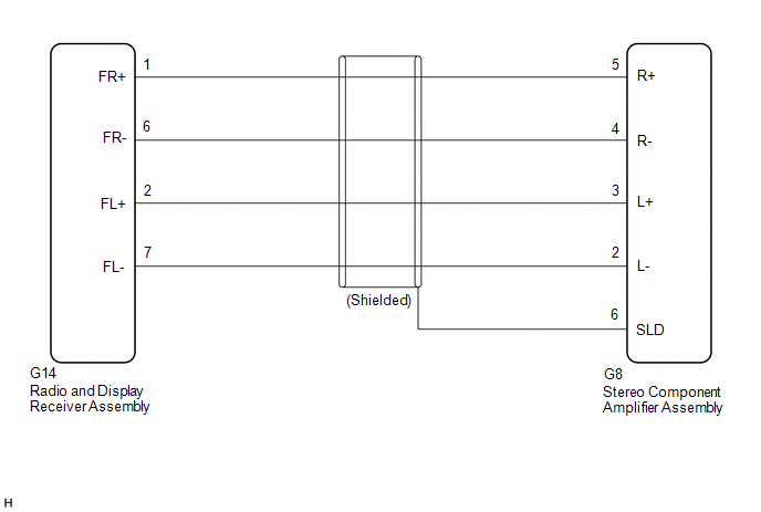
The radio and display receiver assembly sends a sound signal to the stereo component amplifier assembly via this circuit.
The sound signal that is sent is amplified by the stereo component amplifier assembly, and then is sent to the speakers.
If there is an open or short in this circuit, sound cannot be heard from the speakers even if the stereo component amplifier assembly or speakers are not malfunctioning.
WIRING DIAGRAM
PROCEDURE
| 1. |
CHECK HARNESS AND CONNECTOR (RADIO AND DISPLAY RECEIVER ASSEMBLY - STEREO COMPONENT AMPLIFIER ASSEMBLY) |
(a) Disconnect the G14 radio and display receiver assembly connector.
(b) Disconnect the G8 stereo component amplifier assembly connector.
(c) Measure the resistance according to the value(s) in the table below.
Standard Resistance:
|
Tester Connection | Condition |
Specified Condition |
|---|---|---|
|
G8-5 (R+) - G14-1 (FR+) |
Always | Below 1 Ω |
|
G8-4 (R-) - G14-6 (FR-) |
Always | Below 1 Ω |
|
G8-3 (L+) - G14-2 (FL+) |
Always | Below 1 Ω |
|
G8-2 (L-) - G14-7 (FL-) |
Always | Below 1 Ω |
|
G8-6 (SLD) - Body ground |
Always | 10 kΩ or higher |
|
G8-5 (R+) or G14-1 (FR+) - Body ground |
Always | 10 kΩ or higher |
|
G8-4 (R-) or G14-6 (FR-) - Body ground |
Always | 10 kΩ or higher |
|
G8-3 (L+) or G14-2 (FL+) - Body ground |
Always | 10 kΩ or higher |
|
G8-2 (L-) or G14-7 (FL-) - Body ground |
Always | 10 kΩ or higher |
| OK |  | PROCEED TO NEXT SUSPECTED AREA SHOWN IN PROBLEM SYMPTOMS TABLE |
| NG | | REPAIR OR REPLACE HARNESS OR CONNECTOR |
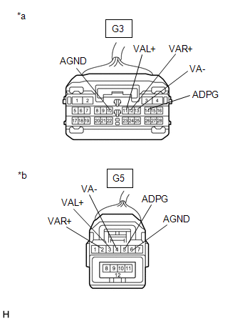
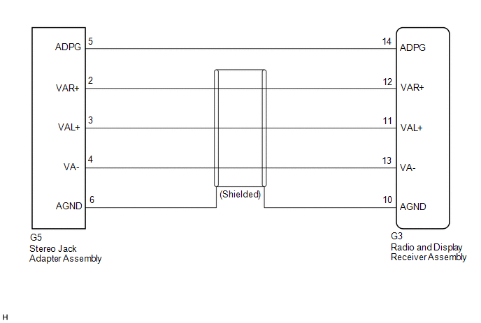
DESCRIPTION
The stereo jack adapter assembly sends the sound signal from an external device to the radio and display receiver assembly via this circuit.
WIRING DIAGRAM
PROCEDURE
| 1. |
CHECK HARNESS AND CONNECTOR (RADIO AND DISPLAY RECEIVER ASSEMBLY - STEREO JACK ADAPTER ASSEMBLY) |
(a) Disconnect the G3 radio and display receiver assembly connector.
(b) Disconnect the G5 stereo jack adapter assembly connector.
| (c) Measure the resistance according to the value(s) in the table below. Standard Resistance:
|
|
| OK |  | PROCEED TO NEXT SUSPECTED AREA SHOWN IN PROBLEM SYMPTOMS TABLE |
| NG | | REPAIR OR REPLACE HARNESS OR CONNECTOR |
DESCRIPTION
for 8 SpeakersThus sound cannot be heard from the speakers even if there is no malfunction in the radio and display receiver assembly, DCM (telematics transceiver)* or speakers.
Thus sound cannot be heard from the speakers even if there is no malfunction in the stereo component amplifier assembly, DCM (telematics transceiver) or speakers.
WIRING DIAGRAM
for 8 Speakers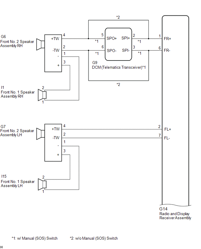
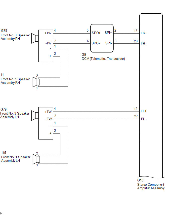
 for 14 Speakers
CAUTION / NOTICE / HINT
NOTICE:
Click here 
Click here
PROCEDURE
|
1. | CHECK MODEL |
(a) Choose the model to be inspected.
|
Result | Proceed to |
|---|---|
|
for 8 Speakers | A |
|
for 14 Speakers | B |
| B |
 | GO TO STEP 13 |
|
| 2. |
CHECK SPEAKER (OPERATION CHECK) |
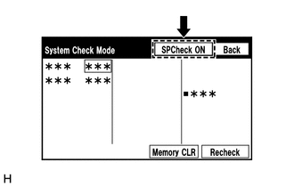
| (a) Enter the "System Check Mode" screen. Refer to Check Speaker in Operation Check. Click here |
|
(b) Perform the operation check above and determine the speaker that is not operating.
|
Not Operating Speaker | Proceed to |
|---|---|
|
Front No. 1 speaker assembly or front No. 2 speaker assembly (w/ Manual (SOS) Switch) |
A |
| Front No. 1 speaker assembly or front No. 2 speaker assembly (w/o Manual (SOS) Switch) |
B |
| Rear speaker assembly or rear No. 2 speaker assembly |
C |
HINT:
If sound cannot be heard from any speaker, inspect all of them.
| B |
| GO TO STEP 7 |
| C |
| GO TO STEP 10 |
|
| 3. |
CHECK HARNESS AND CONNECTOR (RADIO AND DISPLAY RECEIVER ASSEMBLY - FRONT NO. 1 SPEAKER ASSEMBLY - FRONT NO. 2 SPEAKER ASSEMBLY - DCM (TELEMATICS TRANSCEIVER)) |
(a) Disconnect the G14 radio and display receiver assembly connector.
(b) Disconnect the I1 and I15 front No. 1 speaker assembly connectors.
(c) Disconnect the G6 and G7 front No. 2 speaker assembly connectors.
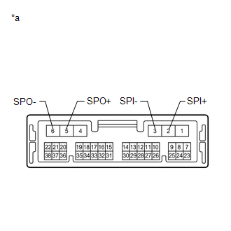
(d) Disconnect the G9 DCM (telematics transceiver) connector.
(e) Measure the resistance according to the value (s) in the table below.
Standard Resistance:
|
Tester Connection | Condition |
Specified Condition |
|---|---|---|
|
G14-1 (FR+) - G9-2 (SPI+) |
Always | Below 1 Ω |
|
G14-6 (FR-) - G9-3 (SPI-) |
Always | Below 1 Ω |
|
G9-5 (SPO+) - G6-4 (+TW) |
Always | Below 1 Ω |
|
G9-6 (SPO-) - G6-2 (-TW) |
Always | Below 1 Ω |
|
G14-2 (FL+) - G7-4 (+TW) |
Always | Below 1 Ω |
|
G14-7 (FL-) - G7-2 (-TW) |
Always | Below 1 Ω |
|
I1-2 - G6-3 (+) | Always |
Below 1 Ω |
|
I1-1 - G6-1 (-) | Always |
Below 1 Ω |
|
I15-2 - G7-3 (+) | Always |
Below 1 Ω |
|
I15-1 - G7-1 (-) | Always |
Below 1 Ω |
|
G14-1 (FR+) or G9-2 (SPI+) - Body ground |
Always | 10 kΩ or higher |
|
G14-6 (FR-) or G9-3 (SPI-) - Body ground |
Always | 10 kΩ or higher |
|
G9-5 (SPO+) or G6-4 (+TW) - Body ground |
Always | 10 kΩ or higher |
|
G9-6 (SPO-) or G6-2 (-TW) - Body ground |
Always | 10 kΩ or higher |
|
G14-2 (FL+) or G7-4 (+TW) - Body ground |
Always | 10 kΩ or higher |
|
G14-7 (FL-) or G7-2 (-TW) - Body ground |
Always | 10 kΩ or higher |
|
I1-2 or G6-3 (+) - Body ground |
Always | 10 kΩ or higher |
|
I1-1 or G6-1 (-) - Body ground |
Always | 10 kΩ or higher |
|
I15-2 or G7-3 (+) - Body ground |
Always | 10 kΩ or higher |
|
I15-1 or G7-1 (-) - Body ground |
Always | 10 kΩ or higher |
| NG | | REPAIR OR REPLACE HARNESS OR CONNECTOR |
|
| 4. |
INSPECT FRONT NO. 1 SPEAKER ASSEMBLY |
(a) Remove the front No. 1 speaker assembly.
Click here
(b) Inspect the front No. 1 speaker assembly.
Click here
| NG | | REPLACE FRONT NO. 1 SPEAKER ASSEMBLY |
|
| 5. |
INSPECT DCM (TELEMATICS TRANSCEIVER) |
(a) Remove the DCM (telematics transceiver).
Click here
| (b) Measure the resistance according to the value(s) in the table below. Standard Resistance:
|
|
| NG | | REPLACE DCM (TELEMATICS TRANSCEIVER) |
|
| 6. |
REPLACE FRONT NO. 2 SPEAKER ASSEMBLY |
(a) Remove the front No. 2 speaker assembly.
Click here
(b) Inspect the front No. 2 speaker assembly.
Click here
OK:
Malfunction disappears.
| OK | | END |
| NG | | PROCEED TO NEXT SUSPECTED AREA SHOWN IN PROBLEM SYMPTOMS TABLE |
| 7. |
CHECK HARNESS AND CONNECTOR (RADIO AND DISPLAY RECEIVER ASSEMBLY - FRONT NO. 1 SPEAKER ASSEMBLY - FRONT NO. 2 SPEAKER ASSEMBLY) |
(a) Disconnect the G14 radio and display receiver assembly connector.
(b) Disconnect the I1 and I15 front No. 1 speaker assembly connectors.
(c) Disconnect the G6 and G7 front No. 2 speaker assembly connectors.
(d) Measure the resistance according to the value (s) in the table below.
Standard Resistance:
|
Tester Connection | Condition |
Specified Condition |
|---|---|---|
|
G14-1 (FR+) - G6-4 (+TW) |
Always | Below 1 Ω |
|
G14-6 (FR-) - G6-2 (-TW) |
Always | Below 1 Ω |
|
G14-2 (FL+) - G7-4 (+TW) |
Always | Below 1 Ω |
|
G14-7 (FL-) - G7-2 (-TW) |
Always | Below 1 Ω |
|
I1-2 - G6-3 (+) | Always |
Below 1 Ω |
|
I1-1 - G6-1 (-) | Always |
Below 1 Ω |
|
I15-2 - G7-3 (+) | Always |
Below 1 Ω |
|
I15-1 - G7-1 (-) | Always |
Below 1 Ω |
|
G14-1 (FR+) or G6-4 (+TW) - Body ground |
Always | 10 kΩ or higher |
|
G14-6 (FR-) or G6-2 (-TW) - Body ground |
Always | 10 kΩ or higher |
|
G14-2 (FL+) or G7-4 (+TW) - Body ground |
Always | 10 kΩ or higher |
|
G14-7 (FL-) or G7-2 (-TW) - Body ground |
Always | 10 kΩ or higher |
|
I1-2 or G6-3 (+) - Body ground |
Always | 10 kΩ or higher |
|
I1-1 or G6-1 (-) - Body ground |
Always | 10 kΩ or higher |
|
I15-2 or G7-3 (+) - Body ground |
Always | 10 kΩ or higher |
|
I15-1 or G7-1 (-) - Body ground |
Always | 10 kΩ or higher |
| NG | | REPAIR OR REPLACE HARNESS OR CONNECTOR |
|
| 8. |
INSPECT FRONT NO. 1 SPEAKER ASSEMBLY |
(a) Remove the front No. 1 speaker assembly.
Click here
(b) Inspect the front No. 1 speaker assembly.
Click here
| NG | | REPLACE FRONT NO. 1 SPEAKER ASSEMBLY |
|
| 9. |
REPLACE FRONT NO. 2 SPEAKER ASSEMBLY |
(a) Remove the front No. 2 speaker assembly.
Click here
(b) Inspect the front No. 2 speaker assembly.
Click here
OK:
Malfunction disappears.
| OK | | END |
| NG | | PROCEED TO NEXT SUSPECTED AREA SHOWN IN PROBLEM SYMPTOMS TABLE |
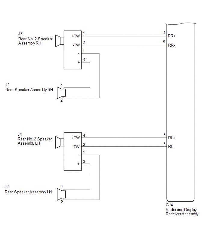
| 10. |
CHECK HARNESS AND CONNECTOR (RADIO AND DISPLAY RECEIVER ASSEMBLY - REAR SPEAKER ASSEMBLY - REAR NO. 2 SPEAKER ASSEMBLY) |
(a) Disconnect the G14 radio and display receiver assembly connector.
(b) Disconnect the J1 and J2 rear speaker assembly connectors.
(c) Disconnect the J3 and J4 rear No. 2 speaker assembly connectors.
(d) Measure the resistance according to the value (s) in the table below.
Standard Resistance:
|
Tester Connection | Condition |
Specified Condition |
|---|---|---|
|
G14-4 (RR+) - J3-4 (+TW) |
Always | Below 1 Ω |
|
G14-9 (RR-) - J3-2 (-TW) |
Always | Below 1 Ω |
|
G14-3 (RL+) - J4-4 (+TW) |
Always | Below 1 Ω |
|
G14-8 (RL-) - J4-2 (-TW) |
Always | Below 1 Ω |
|
J1-1 - J3-3 (+) | Always |
Below 1 Ω |
|
J1-2 - J3-1 (-) | Always |
Below 1 Ω |
|
J2-1 - J4-3 (+) | Always |
Below 1 Ω |
|
J2-2 - J4-1 (-) | Always |
Below 1 Ω |
|
G14-4 (RR+) or J3-4 (+TW) - Body ground |
Always | 10 kΩ or higher |
|
G14-9 (RR-) or J3-2 (-TW) - Body ground |
Always | 10 kΩ or higher |
|
G14-3 (RL+) or J4-4 (+TW) - Body ground |
Always | 10 kΩ or higher |
|
G14-8 (RL-) or J4-2 (-TW) - Body ground |
Always | 10 kΩ or higher |
|
J1-1 or J3-3 (+) - Body ground |
Always | 10 kΩ or higher |
|
J1-2 or J3-1 (-) - Body ground |
Always | 10 kΩ or higher |
|
J2-1 or J4-3 (+) - Body ground |
Always | 10 kΩ or higher |
|
J2-2 or J4-1 (-) - Body ground |
Always | 10 kΩ or higher |
| NG | | REPAIR OR REPLACE HARNESS OR CONNECTOR |
|
| 11. |
INSPECT REAR SPEAKER ASSEMBLY |
(a) Remove the rear speaker assembly.
Click here
(b) Inspect the rear speaker assembly.
Click here
| NG | | REPLACE REAR SPEAKER ASSEMBLY |
|
| 12. |
REPLACE REAR NO. 2 SPEAKER ASSEMBLY |
(a) Remove the rear No. 2 speaker assembly.
Click here
(b) Inspect the rear No. 2 speaker assembly.
Click here
OK:
Malfunction disappears.
| OK | | END |
| NG | | PROCEED TO NEXT SUSPECTED AREA SHOWN IN PROBLEM SYMPTOMS TABLE |
| 13. |
CHECK SPEAKER (OPERATION CHECK) |
| (a) Enter the "System Check Mode" screen. Refer to Check Speaker in Operation Check. Click here |
|
(b) Perform the operation check above and determine the speaker that is not operating.
|
Not Operating Speaker | Proceed to |
|---|---|
|
Front No. 1 speaker assembly or front No. 3 speaker assembly |
A |
| Front No. 2 speaker assembly |
B |
| Front No. 4 speaker assembly |
C |
| Rear speaker assembly or rear No. 2 speaker assembly |
D |
| Speaker assembly with bracket |
E |
| Rear No. 3 speaker assembly |
F |
HINT:
If sound cannot be heard from any speaker, inspect all of them.
| B |
| GO TO STEP 18 |
| C |
| GO TO STEP 20 |
| D |
| GO TO STEP 22 |
| E |
| GO TO STEP 25 |
| F |
| GO TO STEP 27 |
|
| 14. |
CHECK HARNESS AND CONNECTOR (STEREO COMPONENT AMPLIFIER ASSEMBLY - FRONT NO. 1 SPEAKER ASSEMBLY - FRONT NO. 3 SPEAKER ASSEMBLY - DCM (TELEMATICS TRANSCEIVER)) |
(a) Disconnect the G10 stereo component amplifier assembly connector.
(b) Disconnect the I1 and I15 front No. 1 speaker assembly connectors.
(c) Disconnect the G78 and G79 front No. 3 speaker assembly connectors.
(d) Disconnect the G9 DCM (telematics transceiver) connector.
(e) Measure the resistance according to the value (s) in the table below.
Standard Resistance:
|
Tester Connection | Condition |
Specified Condition |
|---|---|---|
|
G10-13 (FR+) - G9-2 (SPI+) |
Always | Below 1 Ω |
|
G10-28 (FR-) - G9-3 (SPI-) |
Always | Below 1 Ω |
|
G9-5 (SPO+) - G78-4 (+TW) |
Always | Below 1 Ω |
|
G9-6 (SPO-) - G78-2 (-TW) |
Always | Below 1 Ω |
|
G10-12 (FL+) - G79-4 (+TW) |
Always | Below 1 Ω |
|
G10-27 (FL-) - G79-2 (-TW) |
Always | Below 1 Ω |
|
I1-2 - G78-3 (+) | Always |
Below 1 Ω |
|
I1-1 - G78-1 (-) | Always |
Below 1 Ω |
|
I15-2 - G79-3 (+) | Always |
Below 1 Ω |
|
I15-1 - G79-1 (-) | Always |
Below 1 Ω |
|
G10-13 (FR+) or G9-2 (SPI+) - Body ground |
Always | 10 kΩ or higher |
|
G10-28 (FR-) or G9-3 (SPI-) - Body ground |
Always | 10 kΩ or higher |
|
G9-5 (SPO+) or G78-4 (+TW) - Body ground |
Always | 10 kΩ or higher |
|
G9-6 (SPO-) or G78-2 (-TW) - Body ground |
Always | 10 kΩ or higher |
|
G10-12 (FL+) or G79-4 (+TW) - Body ground |
Always | 10 kΩ or higher |
|
G10-27 (FL-) or G79-2 (-TW) - Body ground |
Always | 10 kΩ or higher |
|
I1-2 or G78-3 (+) - Body ground |
Always | 10 kΩ or higher |
|
I1-1 or G78-1 (-) - Body ground |
Always | 10 kΩ or higher |
|
I15-2 or G79-3 (+) - Body ground |
Always | 10 kΩ or higher |
|
I15-1 or G79-1 (-) - Body ground |
Always | 10 kΩ or higher |
| NG | | REPAIR OR REPLACE HARNESS OR CONNECTOR |
|
| 15. |
INSPECT FRONT NO. 1 SPEAKER ASSEMBLY |
(a) Remove the front No. 1 speaker assembly.
Click here
(b) Inspect the front No. 1 speaker assembly.
Click here
| NG | | REPLACE FRONT NO. 1 SPEAKER ASSEMBLY |
|
| 16. |
INSPECT DCM (TELEMATICS TRANSCEIVER) |
(a) Remove the DCM (telematics transceiver).
Click here
| (b) Measure the resistance according to the value(s) in the table below. Standard Resistance:
|
|
| NG | | REPLACE DCM (TELEMATICS TRANSCEIVER) |
|
| 17. |
REPLACE FRONT NO. 3 SPEAKER ASSEMBLY |
(a) Remove the front No. 3 speaker assembly.
Click here
(b) Inspect the front No. 3 speaker assembly.
Click here
OK:
Malfunction disappears.
| OK | | END |
| NG | | PROCEED TO NEXT SUSPECTED AREA SHOWN IN PROBLEM SYMPTOMS TABLE |
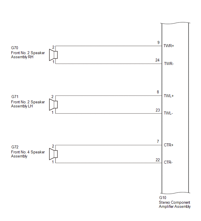
| 18. |
CHECK HARNESS AND CONNECTOR (STEREO COMPONENT AMPLIFIER ASSEMBLY - FRONT NO. 2 SPEAKER ASSEMBLY) |
(a) Disconnect the G10 stereo component amplifier assembly connector.
(b) Disconnect the G70 and G71 front No. 2 speaker assembly connectors.
(c) Measure the resistance according to the value (s) in the table below.
Standard Resistance:
|
Tester Connection | Condition |
Specified Condition |
|---|---|---|
|
G10-9 (TWR+) - G70-2 |
Always | Below 1 Ω |
|
G10-24 (TWR-) - G70-1 |
Always | Below 1 Ω |
|
G10-8 (TWL+) - G71-2 |
Always | Below 1 Ω |
|
G10-23 (TWL-) - G71-1 |
Always | Below 1 Ω |
|
G10-9 (TWR+) or G70-2 - Body ground |
Always | 10 kΩ or higher |
|
G10-24 (TWR-) or G70-1 - Body ground |
Always | 10 kΩ or higher |
|
G10-8 (TWL+) or G71-2 - Body ground |
Always | 10 kΩ or higher |
|
G10-23 (TWL-) or G71-1 - Body ground |
Always | 10 kΩ or higher |
| NG | | REPAIR OR REPLACE HARNESS OR CONNECTOR |
|
| 19. |
INSPECT FRONT NO. 2 SPEAKER ASSEMBLY |
(a) Remove the front No. 2 speaker assembly.
Click here
(b) Inspect the front No. 2 speaker assembly.
Click here
| OK | | PROCEED TO NEXT SUSPECTED AREA SHOWN IN PROBLEM SYMPTOMS TABLE |
| NG | | REPLACE FRONT NO. 2 SPEAKER ASSEMBLY |
| 20. |
CHECK HARNESS AND CONNECTOR (STEREO COMPONENT AMPLIFIER ASSEMBLY - FRONT NO. 4 SPEAKER ASSEMBLY) |
(a) Disconnect the G10 stereo component amplifier assembly connector.
(b) Disconnect the G72 front No. 4 speaker assembly connector.
(c) Measure the resistance according to the value (s) in the table below.
Standard Resistance:
|
Tester Connection | Condition |
Specified Condition |
|---|---|---|
|
G10-7 (CTR+) - G72-2 |
Always | Below 1 Ω |
|
G10-22 (CTR-) - G72-1 |
Always | Below 1 Ω |
|
G10-7 (CTR+) or G72-2 - Body ground |
Always | 10 kΩ or higher |
|
G10-22 (CTR-) or G72-1 - Body ground |
Always | 10 kΩ or higher |
| NG | | REPAIR OR REPLACE HARNESS OR CONNECTOR |
|
| 21. |
INSPECT FRONT NO. 4 SPEAKER ASSEMBLY |
(a) Remove the front No. 4 speaker assembly.
Click here
(b) Inspect the front No. 4 speaker assembly.
Click here
| OK | | PROCEED TO NEXT SUSPECTED AREA SHOWN IN PROBLEM SYMPTOMS TABLE |
| NG | | REPLACE FRONT NO. 4 SPEAKER ASSEMBLY |
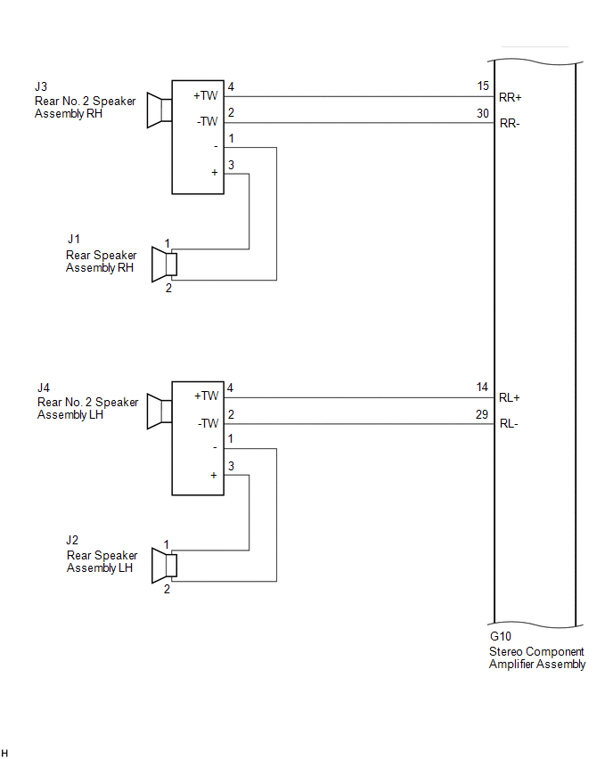
| 22. |
CHECK HARNESS AND CONNECTOR (STEREO COMPONENT AMPLIFIER ASSEMBLY - REAR SPEAKER ASSEMBLY - REAR NO. 2 SPEAKER ASSEMBLY) |
(a) Disconnect the G10 stereo component amplifier assembly connector.
(b) Disconnect the J1 and J2 rear speaker assembly connectors.
(c) Disconnect the J3 and J4 rear No. 2 speaker assembly connectors.
(d) Measure the resistance according to the value (s) in the table below.
Standard Resistance:
|
Tester Connection | Condition |
Specified Condition |
|---|---|---|
|
G10-15 (RR+) - J3-4 (+TW) |
Always | Below 1 Ω |
|
G10-30 (RR-) - J3-2 (-TW) |
Always | Below 1 Ω |
|
G10-14 (RL+) - J4-4 (+TW) |
Always | Below 1 Ω |
|
G10-29 (RL-) - J4-2 (-TW) |
Always | Below 1 Ω |
|
J1-1 - J3-3 (+) | Always |
Below 1 Ω |
|
J1-2 - J3-1 (-) | Always |
Below 1 Ω |
|
J2-1 - J4-3 (+) | Always |
Below 1 Ω |
|
J2-2 - J4-1 (-) | Always |
Below 1 Ω |
|
G10-15 (RR+) or J3-4 (+TW) - Body ground |
Always | 10 kΩ or higher |
|
G10-30 (RR-) or J3-2 (-TW) - Body ground |
Always | 10 kΩ or higher |
|
G10-14 (RL+) or J4-4 (+TW) - Body ground |
Always | 10 kΩ or higher |
|
G10-29 (RL-) or J4-2 (-TW) - Body ground |
Always | 10 kΩ or higher |
|
J1-1 or J3-3 (+) - Body ground |
Always | 10 kΩ or higher |
|
J1-2 or J3-1 (-) - Body ground |
Always | 10 kΩ or higher |
|
J2-1 or J4-3 (+) - Body ground |
Always | 10 kΩ or higher |
|
J2-2 or J4-1 (-) - Body ground |
Always | 10 kΩ or higher |
| NG | | REPAIR OR REPLACE HARNESS OR CONNECTOR |
|
| 23. |
INSPECT REAR SPEAKER ASSEMBLY |
(a) Remove the rear speaker assembly.
Click here
(b) Inspect the rear speaker assembly.
Click here
| NG | | REPLACE REAR SPEAKER ASSEMBLY |
|
| 24. |
REPLACE REAR NO. 2 SPEAKER ASSEMBLY |
(a) Remove the rear No. 2 speaker assembly.
Click here
(b) Inspect the rear No. 2 speaker assembly.
Click here
OK:
Malfunction disappears.
| OK | | END |
| NG | | PROCEED TO NEXT SUSPECTED AREA SHOWN IN PROBLEM SYMPTOMS TABLE |
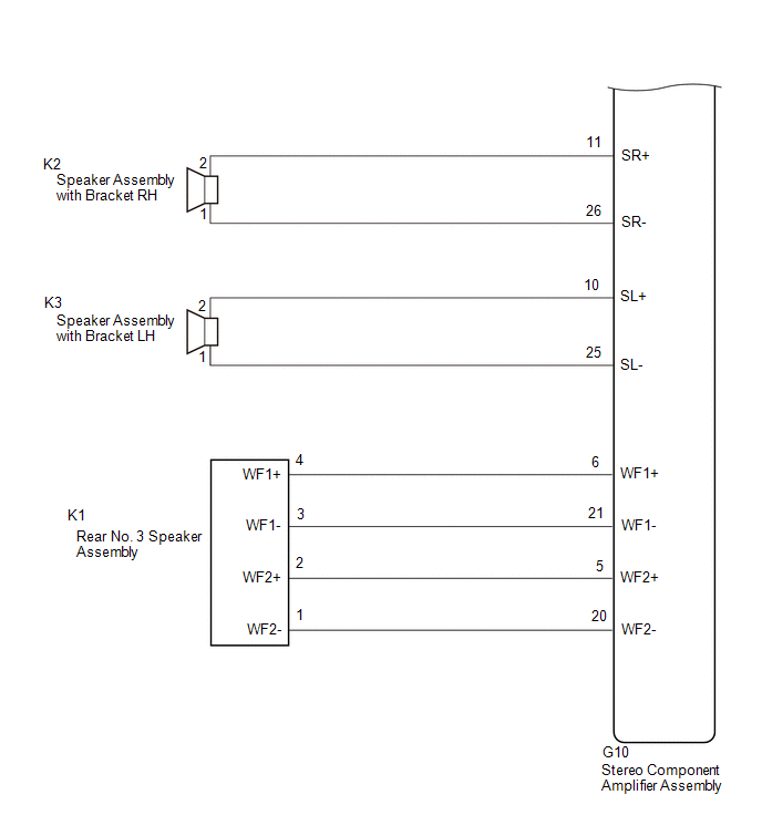
| 25. |
CHECK HARNESS AND CONNECTOR (STEREO COMPONENT AMPLIFIER ASSEMBLY - SPEAKER ASSEMBLY WITH BRACKET) |
(a) Disconnect the G10 stereo component amplifier assembly connector.
(b) Disconnect the K2 and K3 speaker assembly with bracket connectors.
(c) Measure the resistance according to the value (s) in the table below.
Standard Resistance:
|
Tester Connection | Condition |
Specified Condition |
|---|---|---|
|
G10-11 (SR+) - K2-2 | Always |
Below 1 Ω |
|
G10-26 (SR-) - K2-1 | Always |
Below 1 Ω |
|
G10-10 (SL+) - K3-2 | Always |
Below 1 Ω |
|
G10-25 (SL-) - K3-1 | Always |
Below 1 Ω |
|
G10-11 (SR+) or K2-2 - Body ground |
Always | 10 kΩ or higher |
|
G10-26 (SR-) or K2-1 - Body ground |
Always | 10 kΩ or higher |
|
G10-10 (SL+) or K3-2 - Body ground |
Always | 10 kΩ or higher |
|
G10-25 (SL-) or K3-1 - Body ground |
Always | 10 kΩ or higher |
| NG | | REPAIR OR REPLACE HARNESS OR CONNECTOR |
|
| 26. |
INSPECT SPEAKER ASSEMBLY WITH BRACKET |
(a) Remove the speaker assembly with bracket.
Click here
(b) Inspect the speaker assembly with bracket.
Click here
| OK | | PROCEED TO NEXT SUSPECTED AREA SHOWN IN PROBLEM SYMPTOMS TABLE |
| NG | | REPLACE SPEAKER ASSEMBLY WITH BRACKET |
| 27. |
CHECK HARNESS AND CONNECTOR (STEREO COMPONENT AMPLIFIER ASSEMBLY - REAR NO. 3 SPEAKER ASSEMBLY) |
(a) Disconnect the G10 stereo component amplifier assembly connector.
(b) Disconnect the K1 rear No. 3 speaker assembly connector.
(c) Measure the resistance according to the value(s) in the table below.
Standard Resistance:
|
Tester Connection | Condition |
Specified Condition |
|---|---|---|
|
G10-6 (WF1+) - K1-4 (WF1+) |
Always | Below 1 Ω |
|
G10-21 (WF1-) - K1-3 (WF1-) |
Always | Below 1 Ω |
|
G10-5 (WF2+) - K1-2 (WF2+) |
Always | Below 1 Ω |
|
G10-20 (WF2-) - K1-1 (WF2-) |
Always | Below 1 Ω |
|
G10-6 (WF1+) or K1-4 (WF1+) - Body ground |
Always | 10 kΩ or higher |
|
G10-21 (WF1-) or K1-3 (WF1-) - Body ground |
Always | 10 kΩ or higher |
|
G10-5 (WF2+) or K1-2 (WF2+) - Body ground |
Always | 10 kΩ or higher |
|
G10-20 (WF2-) or K1-1 (WF2-) - Body ground |
Always | 10 kΩ or higher |
| NG | | REPAIR OR REPLACE HARNESS OR CONNECTOR |
|
| 28. |
INSPECT REAR NO. 3 SPEAKER ASSEMBLY |
(a) Remove the rear No. 3 speaker assembly.
Click here
(b) Inspect the rear No. 3 speaker assembly.
Click here
| OK | | PROCEED TO NEXT SUSPECTED AREA SHOWN IN PROBLEM SYMPTOMS TABLE |
| NG | | REPLACE REAR NO. 3 SPEAKER ASSEMBLY |
Toyota Avalon (XX50) 2019-2022 Owners Manual > Instrument cluster: Gauges and meters
The units used on the meters may differ depending on the target region. Tachometer Displays the engine speed in revolutions per minute Shift position Outside temperature Displays the outside temperature within the range of -40ºF (-40ºC) to 122ºF (50ºC). Low outside temperature indicator comes o ...