DESCRIPTION
|
Detection Item | Symptom |
Trouble Area |
|---|---|---|
| Door Mirror ECU LH Communication Stop Mode |
Any of the following conditions are met:
|
|
WIRING DIAGRAM
CAUTION / NOTICE / HINT
CAUTION:
When performing the confirmation driving pattern, obey all speed limits and traffic laws.
NOTICE:
Click here 
Click here
DTC check procedure: Turn the power switch on (IG) and wait for 1 minute or more. Then operate the suspected malfunctioning system and drive the vehicle at 60 km/h (37 mph) or more for 5 minutes or more.
Click here
HINT:
PROCEDURE
|
1. | CHECK FOR OPEN IN CAN BUS LINES (OUTER MIRROR CONTROL ECU ASSEMBLY LH BRANCH LINE) |
(a) Disconnect the cable from the negative (-) auxiliary battery terminal.
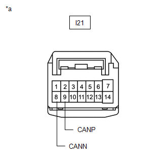
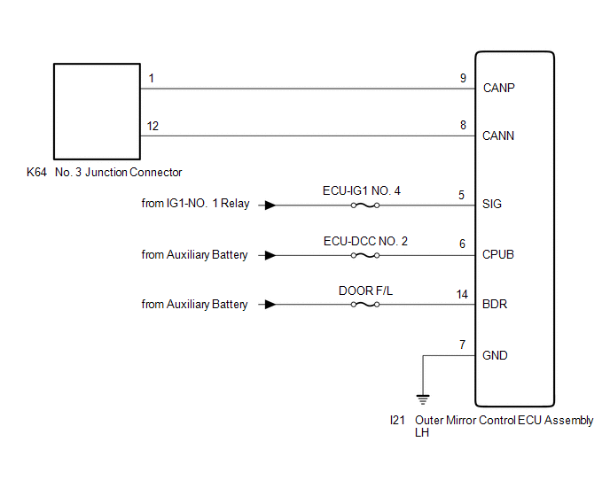
(b) Disconnect the I21 outer mirror control ECU assembly LH connector.
| (c) Measure the resistance according to the value(s) in the table below. Standard Resistance:
|
|
| NG |  | REPAIR OR REPLACE CAN BRANCH LINES OR CONNECTOR (OUTER MIRROR CONTROL ECU ASSEMBLY LH) |
|
| 2. |
CHECK HARNESS AND CONNECTOR (POWER SOURCE CIRCUIT) |
| (a) Measure the resistance according to the value(s) in the table below. Standard Resistance:
|
|
(b) Reconnect the cable to the negative (-) auxiliary battery terminal.
(c) Measure the voltage according to the value(s) in the table below.
Standard Voltage:
|
Tester Connection | Condition |
Specified Condition |
|---|---|---|
|
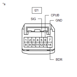
I21-5 (SIG) - Body ground |
Power switch on (IG) |
11 to 14 V |
|
I21-6 (CPUB) - Body ground |
Power switch off | 11 to 14 V |
|
I21-14 (BDR) - Body ground |
Power switch off | 11 to 14 V |
| OK | | REPLACE OUTER MIRROR CONTROL ECU ASSEMBLY LH |
| NG | | REPAIR OR REPLACE HARNESS OR CONNECTOR (POWER SOURCE CIRCUIT) |
DESCRIPTION
|
Detection Item | Symptom |
Trouble Area |
|---|---|---|
| Door Mirror ECU RH Communication Stop Mode |
Any of the following conditions are met:
|
|
WIRING DIAGRAM
CAUTION / NOTICE / HINT
CAUTION:
When performing the confirmation driving pattern, obey all speed limits and traffic laws.
NOTICE:
Click here 
Click here
DTC check procedure: Turn the power switch on (IG) and wait for 1 minute or more. Then operate the suspected malfunctioning system and drive the vehicle at 60 km/h (37 mph) or more for 5 minutes or more.
Click here
HINT:
PROCEDURE
|
1. | CHECK FOR OPEN IN CAN BUS LINES (OUTER MIRROR CONTROL ECU ASSEMBLY RH BRANCH LINE) |
(a) Disconnect the cable from the negative (-) auxiliary battery terminal.
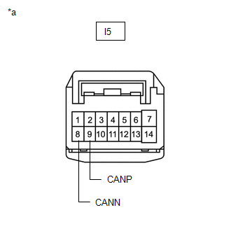
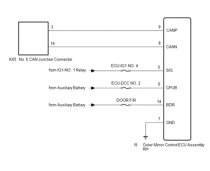
(b) Disconnect the I5 outer mirror control ECU assembly RH connector.
| (c) Measure the resistance according to the value(s) in the table below. Standard Resistance:
|
|
| NG |  | REPAIR OR REPLACE CAN BRANCH LINES OR CONNECTOR (OUTER MIRROR CONTROL ECU ASSEMBLY RH) |
|
| 2. |
CHECK HARNESS AND CONNECTOR (POWER SOURCE CIRCUIT) |
| (a) Measure the resistance according to the value(s) in the table below. Standard Resistance:
|
|
(b) Reconnect the cable to the negative (-) auxiliary battery terminal.
(c) Measure the voltage according to the value(s) in the table below.
Standard Voltage:
|
Tester Connection | Condition |
Specified Condition |
|---|---|---|
|
I5-5 (SIG) - Body ground |
Power switch on (IG) |
11 to 14 V |
|
I5-6 (CPUB) - Body ground |
Power switch off | 11 to 14 V |
|
I5-14 (BDR) - Body ground |
Power switch off | 11 to 14 V |
| OK | | REPLACE OUTER MIRROR CONTROL ECU ASSEMBLY RH |
| NG | | REPAIR OR REPLACE HARNESS OR CONNECTOR (POWER SOURCE CIRCUIT) |
DESCRIPTION
|
Detection Item | Symptom |
Trouble Area |
|---|---|---|
| Driver Seat Control ECU Communication Stop Mode |
Any of the following conditions are met:
|
|
WIRING DIAGRAM
CAUTION / NOTICE / HINT
CAUTION:
When performing the confirmation driving pattern, obey all speed limits and traffic laws.
NOTICE:
Click here 
Click here
DTC check procedure: Turn the power switch on (IG) and wait for 1 minute or more. Then operate the suspected malfunctioning system and drive the vehicle at 60 km/h (37 mph) or more for 5 minutes or more.
Click here
HINT:
PROCEDURE
|
1. | CHECK FOR OPEN IN CAN BUS LINES (POSITION CONTROL ECU ASSEMBLY LH BRANCH LINE) |
(a) Disconnect the cable from the negative (-) auxiliary battery terminal.
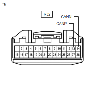
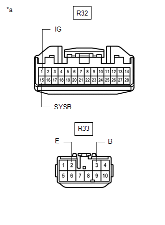
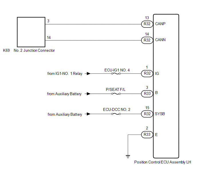
(b) Disconnect the R32 position control ECU assembly LH connector.
| (c) Measure the resistance according to the value(s) in the table below. Standard Resistance:
|
|
| NG |  | REPAIR OR REPLACE CAN BRANCH LINES OR CONNECTOR (POSITION CONTROL ECU ASSEMBLY LH) |
|
| 2. |
CHECK HARNESS AND CONNECTOR (POWER SOURCE CIRCUIT) |
(a) Disconnect the R33 position control ECU assembly LH connector.
| (b) Measure the resistance according to the value(s) in the table below. Standard Resistance:
|
|
(c) Reconnect the cable to the negative (-) auxiliary battery terminal.
(d) Measure the voltage according to the value(s) in the table below.
Standard Voltage:
|
Tester Connection | Condition |
Specified Condition |
|---|---|---|
|
R33-3 (B) - Body ground |
Power switch off | 11 to 14 V |
|
R32-1 (IG) - Body ground |
Power switch on (IG) |
11 to 14 V |
|
R32-15 (SYSB) - Body ground |
Power switch off | 11 to 14 V |
| OK | | REPLACE POSITION CONTROL ECU ASSEMBLY LH |
| NG | | REPAIR OR REPLACE HARNESS OR CONNECTOR (POWER SOURCE CIRCUIT) |
Toyota Avalon (XX50) 2019-2022 Service & Repair Manual > 2gr-fks Battery / Charging: Charging System
Charging Failure PROCEDURE 1. CHECK GENERATOR PULLEY WITH CLUTCH (ON-VEHICLE INSPECTION) (a) Start the engine and visually check that the generator rotor assembly (fan) in the generator assembly is operating. OK: The generator rotor assembly (fan) is operating. NG REPLACE GENERATOR PULLEY WITH CLUTC ...