DESCRIPTION
There may be an open circuit in one of the CAN main bus lines when the resistance between terminals 22 (CA2H) and 7 (CA2L) of the central gateway ECU (network gateway ECU) is 70 Ω or higher.
|
Symptom | Trouble Area |
|---|---|
|
Resistance between terminals 22 (CA2H) and 7 (CA2L) of the central gateway ECU (network gateway ECU) is 70 Ω or higher. |
|
This malfunction is not related to the lines of a CAN branch or to ECUs or sensors connected to a CAN branch.
WIRING DIAGRAM
CAUTION / NOTICE / HINT
CAUTION:
When performing the confirmation driving pattern, obey all speed limits and traffic laws.
NOTICE:
Click here 
Click here
DTC check procedure: Turn the power switch on (IG) and wait for 1 minute or more. Then operate the suspected malfunctioning system and drive the vehicle at 60 km/h (37 mph) or more for 5 minutes or more.
Click here
HINT:
PROCEDURE
|
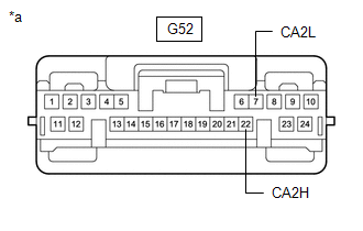
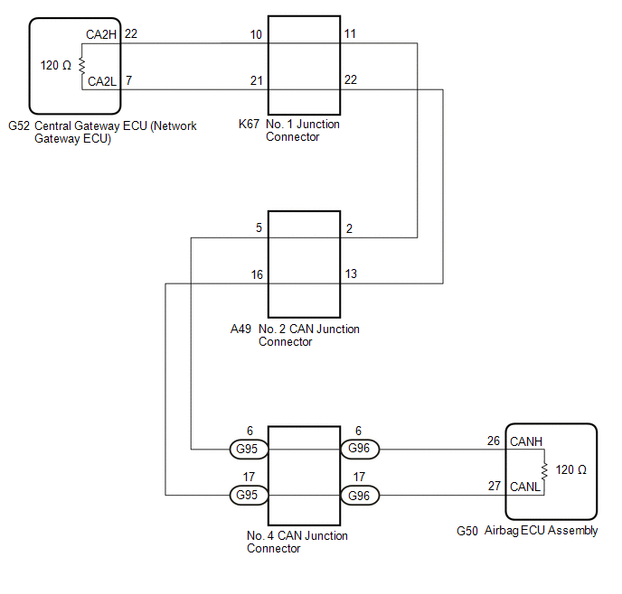
1. | CHECK FOR OPEN IN CAN MAIN BUS LINES (NO. 1 JUNCTION CONNECTOR) |
(a) Disconnect the cable from the negative (-) auxiliary battery terminal.
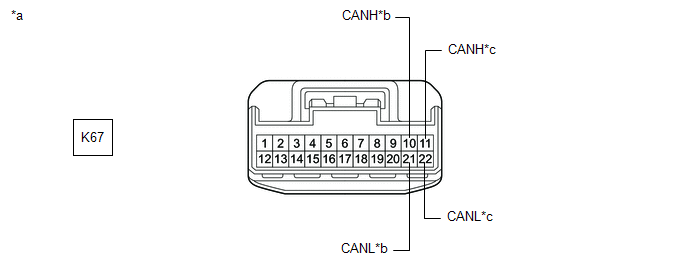
(b) Disconnect the K67 No. 1 junction connector.
(c) Measure the resistance according to the value(s) in the table below.
|
*a | Front view of wire harness connector (to No. 1 Junction Connector) |
*b | to Central Gateway ECU (Network Gateway ECU) |
|
*c | to No. 2 CAN Junction Connector |
- | - |
Standard Resistance:
|
Tester Connection | Condition |
Specified Condition | Connected to |
|---|---|---|---|
|
K67-10 (CANH) - K67-21 (CANL) |
Cable disconnected from negative (-) auxiliary battery terminal |
108 to 132 Ω | Central gateway ECU (network gateway ECU) |
|
K67-11 (CANH) - K67-22 (CANL) |
Cable disconnected from negative (-) auxiliary battery terminal |
108 to 132 Ω | No. 2 CAN junction connector |
|
Result | Proceed to |
|---|---|
|
OK | A |
|
NG (Line to central gateway ECU (network gateway ECU)) |
B |
| NG (Line to No. 2 CAN junction connector) |
C |
| A |
 | REPLACE NO. 1 JUNCTION CONNECTOR |
| C |
| GO TO STEP 3 |
|
| 2. |
CHECK FOR OPEN IN CAN MAIN BUS LINES (CENTRAL GATEWAY ECU (NETWORK GATEWAY ECU) - NO. 1 JUNCTION CONNECTOR) |
(a) Reconnect the K67 No. 1 junction connector.
(b) Disconnect the G52 central gateway ECU (network gateway ECU) connector.
| (c) Measure the resistance according to the value(s) in the table below. Standard Resistance:
|
|
| OK | | REPLACE CENTRAL GATEWAY ECU (NETWORK GATEWAY ECU) |
| NG | | REPAIR OR REPLACE CAN MAIN BUS LINES OR CONNECTOR (CENTRAL GATEWAY ECU (NETWORK GATEWAY ECU) - NO. 1 JUNCTION CONNECTOR) |
| 3. |
CHECK FOR OPEN IN CAN MAIN BUS LINES (NO. 2 CAN JUNCTION CONNECTOR) |
(a) Reconnect the K67 No. 1 junction connector.
(b) Disconnect the A49 No. 2 CAN junction connector.
(c) Measure the resistance according to the value(s) in the table below.
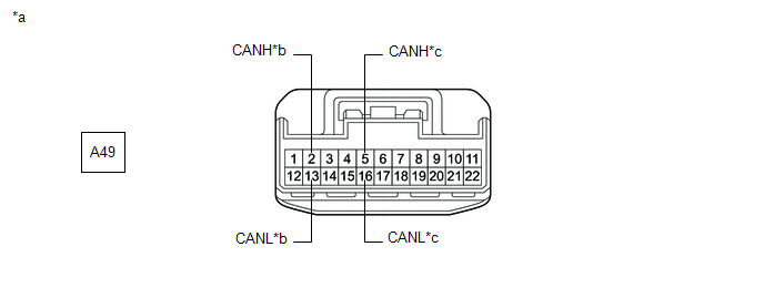
|
*a | Front view of wire harness connector (to No. 2 CAN Junction Connector) |
*b | to No. 1 Junction Connector |
|
*c | to No. 4 CAN Junction Connector |
- | - |
Standard Resistance:
|
Tester Connection | Condition |
Specified Condition | Connected to |
|---|---|---|---|
|
A49-2 (CANH) - A49-13 (CANL) |
Cable disconnected from negative (-) auxiliary battery terminal |
108 to 132 Ω | No. 1 junction connector |
|
A49-5 (CANH) - A49-16 (CANL) |
Cable disconnected from negative (-) auxiliary battery terminal |
108 to 132 Ω | No. 4 CAN junction connector |
|
Result | Proceed to |
|---|---|
|
OK | A |
|
NG (Line to No. 1 junction connector) |
B |
| NG (Line to No. 4 CAN junction connector) |
C |
| A |
| REPLACE NO. 2 CAN JUNCTION CONNECTOR |
| B |
| REPAIR OR REPLACE CAN MAIN BUS LINES OR CONNECTOR (NO. 2 CAN JUNCTION CONNECTOR - NO. 1 JUNCTION CONNECTOR) |
|
| 4. |
CHECK FOR OPEN IN CAN MAIN BUS LINES (NO. 4 CAN JUNCTION CONNECTOR - NO. 2 CAN JUNCTION CONNECTOR) |
(a) Reconnect the A49 No. 2 CAN junction connector.
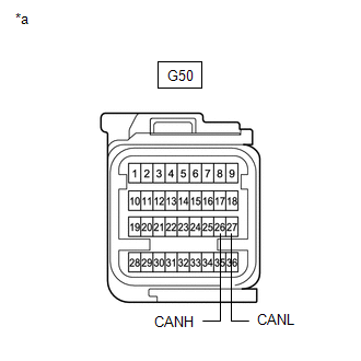
(b) Disconnect the G95 No. 4 CAN junction connector.
(c) Measure the resistance according to the value(s) in the table below.
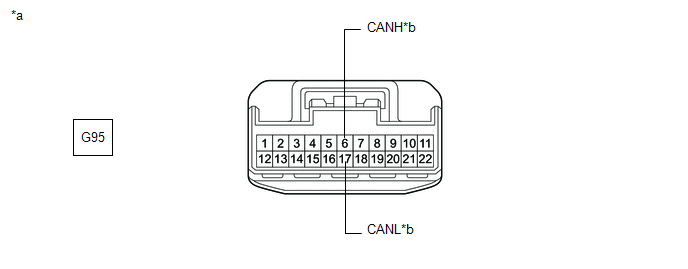
|
*a | Front view of wire harness connector (to No. 4 CAN Junction Connector) |
*b | to No. 2 CAN Junction Connector |
Standard Resistance:
|
Tester Connection | Condition |
Specified Condition |
|---|---|---|
|
G95-6 (CANH) - G95-17 (CANL) |
Cable disconnected from negative (-) auxiliary battery terminal |
108 to 132 Ω |
| NG | | REPAIR OR REPLACE CAN MAIN BUS LINES OR CONNECTOR (NO. 4 CAN JUNCTION CONNECTOR - NO. 2 CAN JUNCTION CONNECTOR) |
|
| 5. |
CHECK FOR OPEN IN CAN MAIN BUS LINES (NO. 4 CAN JUNCTION CONNECTOR) |
(a) Reconnect the G95 No. 4 CAN junction connector.
(b) Disconnect the G96 No. 4 CAN junction connector.
(c) Measure the resistance according to the value(s) in the table below.
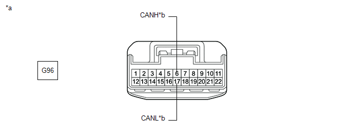
|
*a | Front view of wire harness connector (to No. 4 CAN Junction Connector) |
*b | to Airbag ECU Assembly |
Standard Resistance:
|
Tester Connection | Condition |
Specified Condition |
|---|---|---|
|
G96-6 (CANH) - G96-17 (CANL) |
Cable disconnected from negative (-) auxiliary battery terminal |
108 to 132 Ω |
| OK | | REPLACE NO. 4 CAN JUNCTION CONNECTOR |
|
| 6. |
CHECK FOR OPEN IN CAN MAIN BUS LINES (AIRBAG ECU ASSEMBLY - NO. 4 CAN JUNCTION CONNECTOR) |
(a) Reconnect the G96 No. 4 CAN junction connector.
(b) Disconnect the G50 airbag ECU assembly connector.
| (c) Measure the resistance according to the value(s) in the table below. Standard Resistance:
|
|
| OK | | REPLACE AIRBAG ECU ASSEMBLY |
| NG | | REPAIR OR REPLACE CAN MAIN BUS LINES OR CONNECTOR (AIRBAG ECU ASSEMBLY - NO. 4 CAN JUNCTION CONNECTOR) |
DESCRIPTION
There may be an open circuit in one of the CAN main bus lines when the resistance between terminals 15 (CA5H) and 16 (CA5L) of the central gateway ECU (network gateway ECU) is 70 Ω or higher.
|
Symptom | Trouble Area |
|---|---|
|
Resistance between terminals 15 (CA5H) and 16 (CA5L) of the central gateway ECU (network gateway ECU) is 70 Ω or higher. |
|
This malfunction is not related to the lines of a CAN branch or to ECUs or sensors connected to a CAN branch.
WIRING DIAGRAM

CAUTION / NOTICE / HINT
CAUTION:
When performing the confirmation driving pattern, obey all speed limits and traffic laws.
NOTICE:
Click here 
Click here
DTC check procedure: Turn the power switch on (IG) and wait for 1 minute or more. Then operate the suspected malfunctioning system and drive the vehicle at 60 km/h (37 mph) or more for 5 minutes or more.
Click here
HINT:
PROCEDURE
|
1. | CHECK FOR OPEN IN CAN MAIN BUS LINES (NO. 6 CAN JUNCTION CONNECTOR) |
(a) Disconnect the cable from the negative (-) auxiliary battery terminal.
(b) Disconnect the K65 No. 6 CAN junction connector.
(c) Measure the resistance according to the value(s) in the table below.

|
*a | Front view of wire harness connector (to No. 6 CAN Junction Connector) |
*b | to Central Gateway ECU (Network Gateway ECU) |
|
*c | to No. 2 Junction Connector |
- | - |
Standard Resistance:
|
Tester Connection | Condition |
Specified Condition | Connected to |
|---|---|---|---|
|
K65-1 (CANH) - K65-12 (CANL) |
Cable disconnected from negative (-) auxiliary battery terminal |
108 to 132 Ω | Central gateway ECU (network gateway ECU) |
|
K65-2 (CANH) - K65-13 (CANL) |
Cable disconnected from negative (-) auxiliary battery terminal |
108 to 132 Ω | No. 2 junction connector |
|
Result | Proceed to |
|---|---|
|
OK | A |
|
NG (Line to central gateway ECU (network gateway ECU)) |
B |
| NG (Line to No. 2 junction connector) |
C |
| A |
 | REPLACE NO. 6 CAN JUNCTION CONNECTOR |
| C |
| GO TO STEP 3 |
|
| 2. |
CHECK FOR OPEN IN CAN MAIN BUS LINES (CENTRAL GATEWAY ECU (NETWORK GATEWAY ECU) - NO. 6 CAN JUNCTION CONNECTOR) |
(a) Reconnect the K65 No. 6 CAN junction connector.
(b) Disconnect the G52 central gateway ECU (network gateway ECU) connector.
| (c) Measure the resistance according to the value(s) in the table below. Standard Resistance:
|
|
| OK | | REPLACE CENTRAL GATEWAY ECU (NETWORK GATEWAY ECU) |
| NG | | REPAIR OR REPLACE CAN MAIN BUS LINES OR CONNECTOR (CENTRAL GATEWAY ECU (NETWORK GATEWAY ECU) - NO. 6 CAN JUNCTION CONNECTOR) |
| 3. |
CHECK FOR OPEN IN CAN MAIN BUS LINES (NO. 2 JUNCTION CONNECTOR) |
(a) Reconnect the K65 No. 6 CAN junction connector.
(b) Disconnect the K69 No. 2 junction connector.
(c) Measure the resistance according to the value(s) in the table below.

|
*a | Front view of wire harness connector (to No. 2 Junction Connector) |
*b | to No. 6 CAN Junction Connector |
|
*c | to No. 3 Junction Connector |
- | - |
Standard Resistance:
|
Tester Connection | Condition |
Specified Condition | Connected to |
|---|---|---|---|
|
K69-1 (CANH) - K69-12 (CANL) |
Cable disconnected from negative (-) auxiliary battery terminal |
108 to 132 Ω | No. 6 CAN junction connector |
|
K69-2 (CANH) - K69-13 (CANL) |
Cable disconnected from negative (-) auxiliary battery terminal |
108 to 132 Ω | No. 3 junction connector |
|
Result | Proceed to |
|---|---|
|
OK | A |
|
NG (Line to No. 6 CAN junction connector) |
B |
| NG (Line to No. 3 junction connector) |
C |
| A |
| REPLACE NO. 2 JUNCTION CONNECTOR |
| B |
| REPAIR OR REPLACE CAN MAIN BUS LINES OR CONNECTOR (NO. 2 JUNCTION CONNECTOR - NO. 6 CAN JUNCTION CONNECTOR) |
|
| 4. |
CHECK FOR OPEN IN CAN MAIN BUS LINES (NO. 3 JUNCTION CONNECTOR) |
(a) Reconnect the K69 No. 2 junction connector.
(b) Disconnect the K64 No. 3 junction connector.
(c) Measure the resistance according to the value(s) in the table below.

|
*a | Front view of wire harness connector (to No. 3 Junction Connector) |
*b | to No. 3 CAN Junction Connector |
|
*c | to No. 2 Junction Connector |
- | - |
Standard Resistance:
|
Tester Connection | Condition |
Specified Condition | Connected to |
|---|---|---|---|
|
K64-3 (CANH) - K64-14 (CANL) |
Cable disconnected from negative (-) auxiliary battery terminal |
108 to 132 Ω | No. 3 CAN junction connector |
|
K64-4 (CANH) - K64-15 (CANL) |
Cable disconnected from negative (-) auxiliary battery terminal |
108 to 132 Ω | No. 2 junction connector |
|
Result | Proceed to |
|---|---|
|
OK | A |
|
NG (Line to No. 3 CAN junction connector) |
B |
| NG (Line to No. 2 junction connector) |
C |
| A |
| REPLACE NO. 3 JUNCTION CONNECTOR |
| C |
| REPAIR OR REPLACE CAN MAIN BUS LINES OR CONNECTOR (NO. 3 JUNCTION CONNECTOR - NO. 2 JUNCTION CONNECTOR) |
|
| 5. |
CHECK FOR OPEN IN CAN MAIN BUS LINES (NO. 3 CAN JUNCTION CONNECTOR) |
(a) Reconnect the K64 No. 3 junction connector.
(b) Disconnect the G94 No. 3 CAN junction connector.
(c) Measure the resistance according to the value(s) in the table below.

|
*a | Front view of wire harness connector (to No. 3 CAN Junction Connector) |
*b | to No. 3 Junction Connector |
|
*c | to Combination Meter Assembly |
- | - |
Standard Resistance:
|
Tester Connection | Condition |
Specified Condition | Connected to |
|---|---|---|---|
|
G94-3 (CANH) - G94-14 (CANL) |
Cable disconnected from negative (-) auxiliary battery terminal |
108 to 132 Ω | No. 3 junction connector |
|
G94-5 (CANH) - G94-16 (CANL) |
Cable disconnected from negative (-) auxiliary battery terminal |
108 to 132 Ω | Combination meter assembly |
|
Result | Proceed to |
|---|---|
|
OK | A |
|
NG (Line to No. 3 junction connector) |
B |
| NG (Line to Combination meter assembly) |
C |
| A |
| REPLACE NO. 3 CAN JUNCTION CONNECTOR |
| B |
| REPAIR OR REPLACE CAN MAIN BUS LINES OR CONNECTOR (NO. 3 CAN JUNCTION CONNECTOR - NO. 3 JUNCTION CONNECTOR) |
|
| 6. |
CHECK FOR OPEN IN CAN MAIN BUS LINES (COMBINATION METER ASSEMBLY - NO. 3 CAN JUNCTION CONNECTOR) |
(a) Reconnect the G94 No. 3 CAN junction connector.
(b) Disconnect the G16 combination meter assembly connector.
| (c) Measure the resistance according to the value(s) in the table below. Standard Resistance:
|
|
| OK | | REPLACE COMBINATION METER ASSEMBLY |
| NG | | REPAIR OR REPLACE CAN MAIN BUS LINES OR CONNECTOR (COMBINATION METER ASSEMBLY - NO. 3 CAN JUNCTION CONNECTOR) |
DESCRIPTION
When the CAN bus main lines are normal (no open, short to ground, short to +B or short between lines) and there is an ECU or sensor on the "Communication Bus Check" screen that is indicated as not communicating or whose connection status on the "Communication Bus Check" screen changes intermittently, an open in one of the wires of a CAN bus branch line is suspected.
HINT:
If there is an ECU or sensor whose connection status changes intermittently while checking the "Communication Bus Check" screen, there may be an open circuit in one of the wires of a branch line of an ECU or sensor in the bus. If an open occurs in one of the wires of a CAN branch line, it may interfere with the communication of other ECUs or sensors resulting in an incorrect state being displayed.
|
Symptom | Trouble Area |
|---|---|
|
There is an ECU or sensor that is indicated as not communicating on the "Communication Bus Check" screen or whose connection status on the "Communication Bus Check" screen changes intermittently. |
One side of CAN branch line is open, or output signals are incomplete.
|
CAUTION / NOTICE / HINT
CAUTION:
When performing the confirmation driving pattern, obey all speed limits and traffic laws.
NOTICE:
Click here 
DTC check procedure: Turn the power switch on (IG) and wait for 1 minute or more. Then operate the suspected malfunctioning system and drive the vehicle at 60 km/h (37 mph) or more for 5 minutes or more.
Click here
PROCEDURE
|
1. | CHECK FOR OPEN IN ONE SIDE OF CAN BRANCH LINE |
(a) Based on the vehicle equipment and specifications, confirm the systems that use CAN communication.
Click here
(b) Connect the Techstream to the DLC3.
(c) Turn the power switch on (IG).
(d) Turn the Techstream on.
(e) Using the Techstream, perform "CAN Bus Check".
CAN Bus Check(f) Observe the screen for approximately 2 minutes to check for ECUs and sensors that are displayed as not communicating.
(g) Perform the inspection as specified in the Problem Symptoms Table for the ECUs or sensors that are not communicating.
| NEXT |  | GO TO CORRESPONDING COMMUNICATION STOP MODE |
Toyota Avalon (XX50) 2019-2022 Service & Repair Manual > Hybrid Control System: Hybrid/EV Battery Block 1 Circuit Resistance Out of Range (Extreme) (P301100,...,P30211E)
DESCRIPTION Refer to the description for DTC P1AC000. Click here DTC No. Detection Item DTC Detection Condition Trouble Area MIL Warning Indicate P301100 Hybrid/EV Battery Block 1 Circuit Resistance Out of Range (Extreme) An internal malfunction of the HV battery is detected. The difference in the i ...