DESCRIPTION
When the CAN bus main lines are normal (no open, short to ground, short to +B or short between lines) and there is an ECU or sensor on the "Communication Bus Check" screen that is indicated as not communicating or whose connection status on the "Communication Bus Check" screen changes intermittently, an open in one of the wires of a CAN bus branch line is suspected.
HINT:
If there is an ECU or sensor whose connection status changes intermittently while checking the "Communication Bus Check" screen, there may be an open circuit in one of the wires of a branch line of an ECU or sensor in the bus. If an open occurs in one of the wires of a CAN branch line, it may interfere with the communication of other ECUs or sensors resulting in an incorrect state being displayed.
|
Symptom | Trouble Area |
|---|---|
|
There is an ECU or sensor that is indicated as not communicating on the "Communication Bus Check" screen or whose connection status on the "Communication Bus Check" screen changes intermittently. |
One side of CAN branch line is open, or output signals are incomplete.
|
CAUTION / NOTICE / HINT
CAUTION:
When performing the confirmation driving pattern, obey all speed limits and traffic laws.
NOTICE:
Click here 
DTC check procedure: Turn the power switch on (IG) and wait for 1 minute or more. Then operate the suspected malfunctioning system and drive the vehicle at 60 km/h (37 mph) or more for 5 minutes or more.
Click here
Click here
PROCEDURE
|
1. | CHECK FOR OPEN IN ONE SIDE OF CAN BRANCH LINE |
(a) Based on the vehicle equipment and specifications, confirm the systems that use CAN communication.
Click here
(b) Connect the Techstream to the DLC3.
(c) Turn the power switch on (IG).
(d) Turn the Techstream on.
(e) Using the Techstream, perform "CAN Bus Check".
CAN Bus Check(f) Observe the screen for approximately 2 minutes to check for ECUs and sensors that are displayed as not communicating.
(g) Perform the inspection as specified in the Problem Symptoms Table for the ECUs or sensors that are not communicating.
| NEXT |  | GO TO CORRESPONDING COMMUNICATION STOP MODE |
DESCRIPTION
|
Detection Item | Symptom |
Trouble Area |
|---|---|---|
| Parking Assist ECU Communication Stop Mode |
Any of the following conditions are met:
|
|
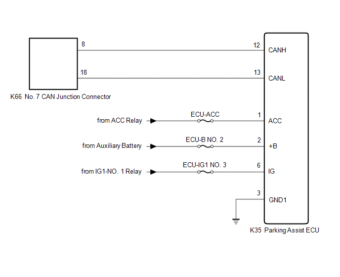
WIRING DIAGRAM
CAUTION / NOTICE / HINT
CAUTION:
When performing the confirmation driving pattern, obey all speed limits and traffic laws.
NOTICE:
Click here 
Click here
DTC check procedure: Turn the power switch on (IG) and wait for 1 minute or more. Then operate the suspected malfunctioning system and drive the vehicle at 60 km/h (37 mph) or more for 5 minutes or more.
Click here
HINT:
PROCEDURE
|
1. | CHECK FOR OPEN IN CAN BUS LINES (PARKING ASSIST ECU BRANCH LINE) |
(a) Disconnect the cable from the negative (-) auxiliary battery terminal.
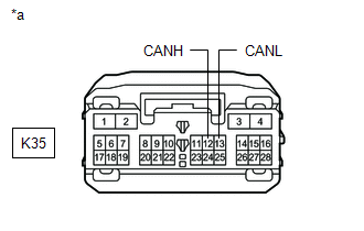
(b) Disconnect the K35 parking assist ECU connector.
| (c) Measure the resistance according to the value(s) in the table below. Standard Resistance:
|
|
| NG |  | REPAIR OR REPLACE CAN BRANCH LINES OR CONNECTOR (PARKING ASSIST ECU) |
|
| 2. |
CHECK HARNESS AND CONNECTOR (POWER SOURCE CIRCUIT) |
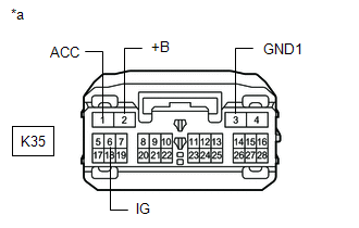
| (a) Measure the resistance according to the value(s) in the table below. Standard Resistance:
|
|
(b) Reconnect the cable to the negative (-) auxiliary battery terminal.
(c) Measure the voltage according to the value(s) in the table below.
Standard Voltage:
|
Tester Connection | Condition |
Specified Condition |
|---|---|---|
|
K35-2 (+B) - Body ground |
Power switch off | 11 to 14 V |
|
K35-6 (IG) - Body ground |
Power switch on (IG) |
11 to 14 V |
|
K35-1 (ACC) - Body ground |
Power switch on (ACC) |
11 to 14 V |
| OK | | REPLACE PARKING ASSIST ECU |
| NG | | REPAIR OR REPLACE HARNESS OR CONNECTOR (POWER SOURCE CIRCUIT) |
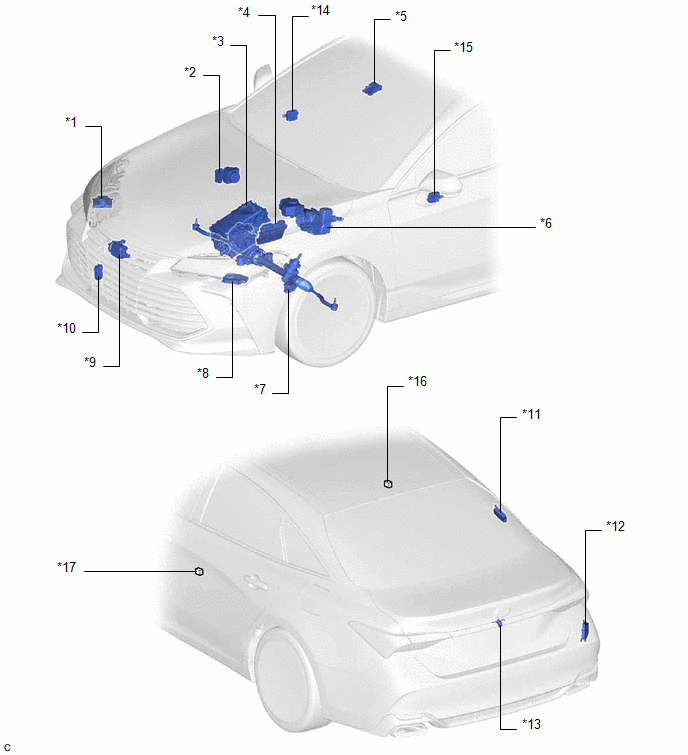
PARTS LOCATION
ILLUSTRATION
|
*1 | HEADLIGHT ECU SUB-ASSEMBLY RH (w/ Cornering Light) | *2 |
BRAKE ACTUATOR ASSEMBLY |
|
*3 | INVERTER WITH CONVERTER ASSEMBLY |
*4 | ECM |
|
*5 | FORWARD RECOGNITION CAMERA |
*6 | BRAKE BOOSTER WITH MASTER CYLINDER ASSEMBLY |
|
*7 | RACK AND PINION POWER STEERING GEAR ASSEMBLY |
*8 | HEADLIGHT ECU SUB-ASSEMBLY LH (w/ Cornering Light) |
|
*9 | MILLIMETER WAVE RADAR SENSOR ASSEMBLY |
*10 | SWING GRILLE ACTUATOR ASSEMBLY |
|
*11 | TIRE PRESSURE WARNING ECU AND RECEIVER |
*12 | BLIND SPOT MONITOR SENSOR RH |
|
*13 | TELEVISION CAMERA ASSEMBLY |
*14 | OUTER MIRROR CONTROL ECU ASSEMBLY RH (w/ Seat Position Memory System) |
|
*15 | OUTER MIRROR CONTROL ECU ASSEMBLY LH (w/ Seat Position Memory System) |
*16 | NO. 1 JUNCTION CONNECTOR |
|
*17 | NO. 2 JUNCTION CONNECTOR |
- | - |
ILLUSTRATION

|
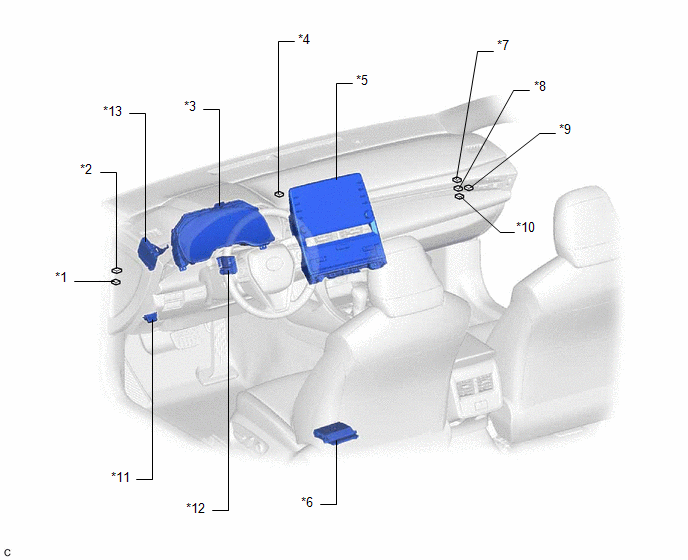
*1 | INSTRUMENT PANEL JUNCTION BLOCK ASSEMBLY |
*2 | MAIN BODY ECU (MULTIPLEX NETWORK BODY ECU) |
|
*3 | METER MIRROR SUB-ASSEMBLY (w/ Headup Display System) |
*4 | AIR CONDITIONING AMPLIFIER ASSEMBLY |
|
*5 | DCM (TELEMATICS TRANSCEIVER) |
*6 | CERTIFICATION ECU (SMART KEY ECU ASSEMBLY) |
|
*7 | CENTRAL GATEWAY ECU (NETWORK GATEWAY ECU) |
*8 | CLEARANCE WARNING ECU ASSEMBLY (w/ Intelligent Clearance Sonar System) |
|
*9 | PARKING ASSIST ECU (w/ Panoramic View Monitor System) |
*10 | OCCUPANT DETECTION ECU |
|
*11 | AIRBAG ECU ASSEMBLY |
*12 | STEERING SENSOR |
|
*13 | HYBRID VEHICLE CONTROL ECU |
- | - |
ILLUSTRATION
|
*1 | NO. 3 JUNCTION CONNECTOR |
*2 | NO. 2 CAN JUNCTION CONNECTOR |
|
*3 | COMBINATION METER ASSEMBLY |
*4 | NO. 3 CAN JUNCTION CONNECTOR |
|
*5 | RADIO AND DISPLAY RECEIVER ASSEMBLY |
*6 | POSITION CONTROL ECU ASSEMBLY LH (w/ Seat Position Memory System) |
|
*7 | NO. 1 CAN JUNCTION CONNECTOR |
*8 | NO. 6 CAN JUNCTION CONNECTOR |
|
*9 | NO. 7 CAN JUNCTION CONNECTOR |
*10 | NO. 4 CAN JUNCTION CONNECTOR |
|
*11 | DLC3 |
*12 | MULTIPLEX TILT AND TELESCOPIC ECU (w/ Power Tilt and Power Telescopic System) |
|
*13 | DRIVING SUPPORT ECU ASSEMBLY |
- | - |
Toyota Avalon (XX50) 2019-2022 Service & Repair Manual > Sfi System: Throttle/Pedal Position Sensor/Switch "B" Circuit Short to Ground (P022011). Throttle/Pedal Position Sensor/Switch "B" Circuit Short to Battery or Open (P022015). Evaporative Emission System Switching
Throttle/Pedal Position Sensor/Switch "B" Circuit Short to Ground (P022011) DESCRIPTION Refer to DTC P012011. Click here DTC No. Detection Item DTC Detection Condition Trouble Area MIL Memory Note P022011 Throttle/Pedal Position Sensor/Switch "B" Circuit Short to Ground The output voltage of VTA2 is ...