Toyota Avalon (XX50) 2019-2022 Service & Repair Manual: Terminals Of Ecu

TERMINALS OF ECU

CHECK INSTRUMENT PANEL JUNCTION BLOCK ASSEMBLY AND MAIN BODY ECU (MULTIPLEX NETWORK BODY ECU)

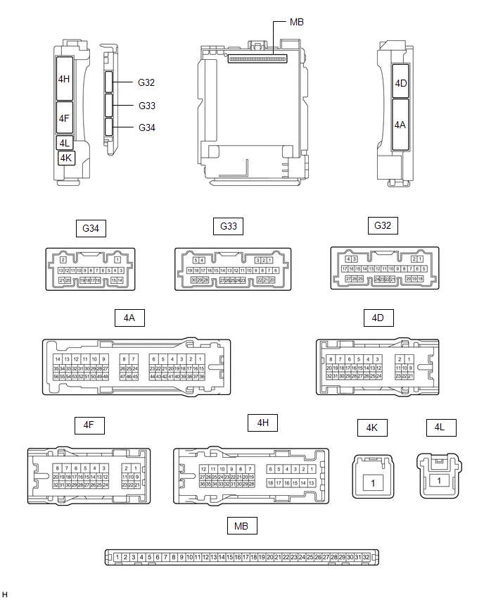
(a) Disconnect the MB main body ECU (multiplex network body ECU) connector.

Click here

(b) Measure the voltage and resistance according to the value(s) in the table below.

HINT:

Measure the values on the wire harness side with the connectors disconnected.

Terminal No. (Symbol)

Wiring Color

Terminal Description

Condition

Specified Condition

MB-11 (GND1) - Body ground

-

Ground

Always

Below 1 Ω

MB-31 (BECU) - Body ground

-

Battery power supply

Always

11 to 14 V

MB-30 (ACC) - Body ground

-

ACC power supply

Engine switch on (ACC)

11 to 14 V

Engine switch off

Below 1 V

MB-32 (IG) - Body ground

-

IG power supply

Engine switch on (IG)

11 to 14 V

Engine switch off

Below 1 V

(c) Reconnect the MB main body ECU (multiplex network body ECU) connector.

(d) Check for pulses according to the value(s) in the table below.

Terminal No. (Symbol)

Wiring Color

Terminal Description

Condition

Specified Condition

4H-25 - Body ground

LA-BE - Body ground

LIN communication line

Engine switch on (IG)

Pulse generation

4D-17 - Body ground*

L - Body ground

LIN communication line

Engine switch on (IG)

Pulse generation

  • *: w/ Sliding Roof System

CHECK POWER WINDOW REGULATOR MOTOR ASSEMBLY (DRIVER DOOR)

(a) Disconnect the I20 power window regulator motor assembly (driver door) connector.

(b) Measure the voltage and resistance according to the value(s) in the table below.

HINT:

Measure the values on the wire harness side with the connector disconnected.

Terminal No. (Symbol)

Wiring Color

Terminal Description

Condition

Specified Condition

I20-2 (B) - Body ground

GR - Body ground

Battery power supply

Always

11 to 14 V

I20-1 (GND) - Body ground

W-B - Body ground

Ground

Always

Below 1 Ω

(c) Reconnect the I20 power window regulator motor assembly (driver door) connector.

(d) Check for pulses according to the value(s) in the table below.

Terminal No. (Symbol)

Wiring Color

Terminal Description

Condition

Specified Condition

I20-9 (LIN) - Body ground

G - Body ground

LIN communication line

Engine switch on (IG)

Pulse generation

CHECK POWER WINDOW REGULATOR MOTOR ASSEMBLY (FRONT PASSENGER DOOR)

(a) Disconnect the I4 power window regulator motor assembly (front passenger door) connector.

(b) Measure the voltage and resistance according to the value(s) in the table below.

HINT:

Measure the values on the wire harness side with the connector disconnected.

Terminal No. (Symbol)

Wiring Color

Terminal Description

Condition

Specified Condition

I4-2 (B) - Body ground

GR - Body ground

Battery power supply

Always

11 to 14 V

I4-1 (GND) - Body ground

W-B - Body ground

Ground

Always

Below 1 Ω

(c) Reconnect the I4 power window regulator motor assembly (front passenger door) connector.

(d) Check for pulses according to the value(s) in the table below.

Terminal No. (Symbol)

Wiring Color

Terminal Description

Condition

Specified Condition

I4-9 (LIN) - Body ground

P - Body ground

LIN communication line

Engine switch on (IG)

Pulse generation

CHECK POWER WINDOW REGULATOR MOTOR ASSEMBLY (REAR RH DOOR)

(a) Disconnect the J9 power window regulator motor assembly (rear RH door) connector.

(b) Measure the voltage and resistance according to the value(s) in the table below.

HINT:

Measure the values on the wire harness side with the connector disconnected.

Terminal No. (Symbol)

Wiring Color

Terminal Description

Condition

Specified Condition

J9-2 (B) - Body ground

B - Body ground

Battery power supply

Always

11 to 14 V

J9-1 (GND) - Body ground

W-B - Body ground

Ground

Always

Below 1 Ω

(c) Reconnect the J9 power window regulator motor assembly (rear RH door) connector.

(d) Check for pulses according to the value(s) in the table below.

Terminal No. (Symbol)

Wiring Color

Terminal Description

Condition

Specified Condition

J9-9 (LIN) - Body ground

P - Body ground

LIN communication line

Engine switch on (IG)

Pulse generation

CHECK POWER WINDOW REGULATOR MOTOR ASSEMBLY (REAR LH DOOR)

(a) Disconnect the J10 power window regulator motor assembly (rear LH door) connector.

(b) Measure the voltage and resistance according to the value(s) in the table below.

HINT:

Measure the values on the wire harness side with the connector disconnected.

Terminal No. (Symbol)

Wiring Color

Terminal Description

Condition

Specified Condition

J10-2 (B) - Body ground

B - Body ground

Battery power supply

Always

11 to 14 V

J10-1 (GND) - Body ground

W-B - Body ground

Ground

Always

Below 1 Ω

(c) Reconnect the J10 power window regulator motor assembly (rear LH door) connector.

(d) Check for pulses according to the value(s) in the table below.

Terminal No. (Symbol)

Wiring Color

Terminal Description

Condition

Specified Condition

J10-9 (LIN) - Body ground

P - Body ground

LIN communication line

Engine switch on (IG)

Pulse generation

CHECK MULTIPLEX NETWORK MASTER SWITCH ASSEMBLY

(a) Disconnect the I16 multiplex network master switch assembly connector.

(b) Measure the voltage and resistance according to the value(s) in the table below.

HINT:

Measure the values on the wire harness side with the connector disconnected.

Terminal No. (Symbol)

Wiring Color

Terminal Description

Condition

Specified Condition

I16-11 (B) - Body ground

LA-R - Body ground

Battery power supply

Always

11 to 14 V

I16-12 (GND) - Body ground

W-B - Body ground

Ground

Always

Below 1 Ω

(c) Reconnect the I16 multiplex network master switch assembly connector.

(d) Check for pulses according to the value(s) in the table below.

Terminal No. (Symbol)

Wiring Color

Terminal Description

Condition

Specified Condition

I16-17 (LIN1) - Body ground

P - Body ground

LIN communication line

Engine switch on (IG)

Pulse generation

I16-16 (LIN2) - Body ground

G - Body ground

LIN communication line

Engine switch on (IG)

Pulse generation

CHECK SLIDING ROOF ECU (SLIDING ROOF DRIVE GEAR ASSEMBLY) (w/ Sliding Roof System)

(a) Disconnect the O3 sliding roof ECU (sliding roof drive gear assembly) connector.

(b) Measure the voltage and resistance according to the value(s) in the table below.

HINT:

Measure the values on the wire harness side with the connector disconnected.

Terminal No. (Symbol)

Wiring Color

Terminal Description

Condition

Specified Condition

O3-1 (B) - Body ground

B - Body ground

Battery power supply

Always

11 to 14 V

O3-2 (E) - Body ground

W-B - Body ground

Ground

Always

Below 1 Ω

(c) Reconnect the O3 sliding roof ECU (sliding roof drive gear assembly) connector.

(d) Check for pulses according to the value(s) in the table below.

Terminal No. (Symbol)

Wiring Color

Terminal Description

Condition

Specified Condition

O3-7 (MPX1) - Body ground

LA-P - Body ground

LIN communication line

Engine switch on (IG)

Pulse generation

CHECK CERTIFICATION ECU (SMART KEY ECU ASSEMBLY)

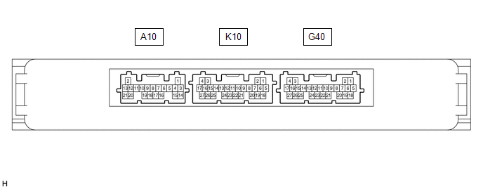
(a) Disconnect the G40 certification ECU (smart key ECU assembly) connector.

(b) Measure the voltage and resistance according to the value(s) in the table below.

HINT:

Measure the values on the wire harness side with the connector disconnected.

Terminal No. (Symbol)

Wiring Color

Terminal Description

Condition

Specified Condition

G40-18 (E) - Body ground

W-B - Body ground

Ground

Always

Below 1 Ω

G40-4 (+B) - Body ground

W - Body ground

Battery power supply

Always

11 to 14 V

(c) Reconnect the G40 certification ECU (smart key ECU assembly) connector.

(d) Check for pulses according to the value(s) in the table below.

Terminal No. (Symbol)

Wiring Color

Terminal Description

Condition

Specified Condition

G40-13 (LIN) - Body ground

B - Body ground

LIN communication line

Engine switch on (IG)

Pulse generation

CHECK STEERING LOCK ECU (STEERING LOCK ACTUATOR OR UPPER BRACKET ASSEMBLY)

(a) Disconnect the G43 steering lock ECU (steering lock actuator or upper bracket assembly) connector.

(b) Measure the resistance and voltage according to the value(s) in the table below.

Terminal No. (Symbol)

Wiring Color

Terminal Description

Condition

Specified Condition

G43-1 (GND) - Body ground

W-B - Body ground

Ground

Always

Below 1 Ω

G43-7 (B) - Body ground

W - Body ground

Battery power supply

Always

11 to 14 V

(c) Reconnect the G43 steering lock ECU (steering lock actuator or upper bracket assembly) connector.

(d) Check for pulses according to the value(s) in the table below.

Terminal No. (Symbol)

Wiring Color

Terminal Description

Condition

Specified Condition

G43-5 (LIN) - Body ground

B - Body ground

LIN communication line

Engine switch on (IG)

Pulse generation

    System Diagram

    Network Gateway Ecu

    See More:

    Toyota Avalon (XX50) 2019-2022 Service & Repair Manual > Front Camera System(for Hv Model): How To Proceed With Troubleshooting
    CAUTION / NOTICE / HINT HINT: Use these procedures to troubleshoot the front camera system. *: Use the Techstream. PROCEDURE 1. VEHICLE BROUGHT TO WORKSHOP NEXT 2. INSPECT AUXILIARY BATTERY VOLTAGE (a) Measure the auxiliary battery voltage with the power switch off. Standard Voltage: 11 to 14 V If t ...

    Toyota Avalon (XX50) 2019-2022 Owners Manual

    Toyota Avalon (XX50) 2019-2022 Service & Repair Manual

    © 2024 Copyright www.tavalon.net
    0.0201