COMPONENTS
ILLUSTRATION
|
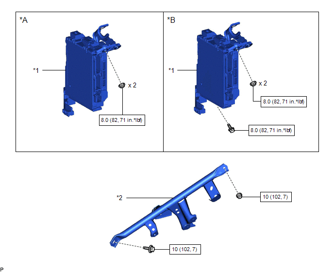
*A | for Gasoline Model |
*B | for HV Model |
|
*1 | INSTRUMENT PANEL JUNCTION BLOCK ASSEMBLY WITH MAIN BODY ECU |
*2 | NO. 3 INSTRUMENT PANEL TO COWL BRACE SUB-ASSEMBLY |
 |
N*m (kgf*cm, ft.*lbf): Specified torque |
- | - |
ILLUSTRATION
|
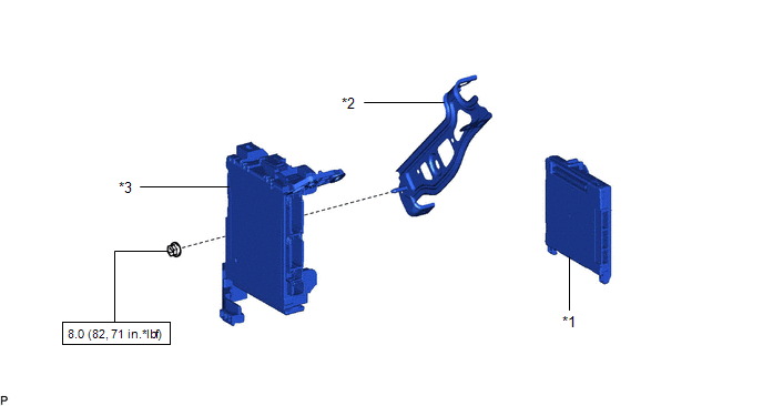
*1 | MAIN BODY ECU (MULTIPLEX NETWORK BODY ECU) |
*2 | WIRING HARNESS CLAMP BRACKET |
|
*3 | INSTRUMENT PANEL JUNCTION BLOCK ASSEMBLY |
- | - |
|
|
N*m (kgf*cm, ft.*lbf): Specified torque |
- | - |
INSTALLATION
CAUTION / NOTICE / HINT
NOTICE:
for Gasoline Model: Click here 
for HV Model: Click here
PROCEDURE
1. INSTALL MAIN BODY ECU (MULTIPLEX NETWORK BODY ECU)
NOTICE:
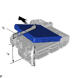
(a) Set the main body ECU (multiplex network body ECU) to the position where the guide of the main body ECU (multiplex network body ECU) contacts the housing sidewall of the instrument panel junction block assembly as shown in the illustration.
|
*a | 20° or more |
|
*b | Housing Sidewall |
 |
Set in this Direction |
HINT:
Make sure to keep the angle at 20° or more as shown in the illustration.
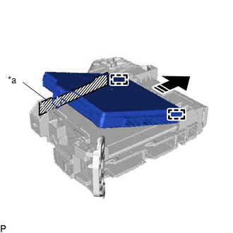
(b) Slide the main body ECU (multiplex network body ECU) along the housing sidewall as shown in the illustration and engage the 2 guides.
|
*a | Housing Sidewall |
|
|
Slide in this Direction |
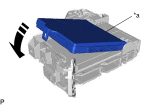
(c) While keeping the main body ECU (multiplex network body ECU) in contact with side A of the instrument panel junction block assembly (axis of rotation), lower it as shown in the illustration.
|
*a | Side A |
|
|
Install in this Direction |
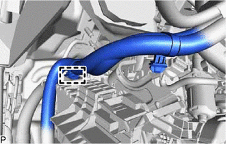
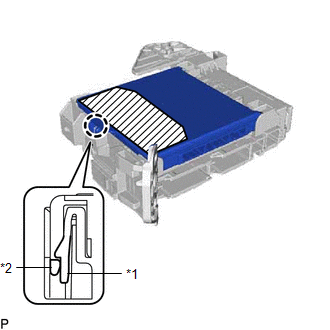
(d) Press the push area until the claw engages to install the main body ECU (multiplex network body ECU).
|
*1 | Instrument Panel Junction Block Assembly |
|
*2 | Main Body ECU (Multiplex Network Body ECU) |
 |
Push Area |
NOTICE:
HINT:
If a click sound cannot be heard, visually check the engagement of the lock. The engagement can also be confirmed if the main body ECU (multiplex network body ECU) and instrument panel junction block assembly are flush.
2. INSTALL WIRING HARNESS CLAMP BRACKET
(a) Engage the guide.
(b) Install the wiring harness clamp bracket with the nut.
Torque:
8.0 N·m {82 kgf·cm, 71 in·lbf}
3. INSTALL INSTRUMENT PANEL JUNCTION BLOCK ASSEMBLY WITH MAIN BODY ECU
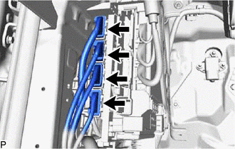
(a) Connect the 2 connectors and raise the 2 lock levers to engage the 2 claws and lock the connector as shown in the illustration.
NOTICE:
Be sure to connect the connector securely.
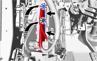
|
| Install in this Direction |
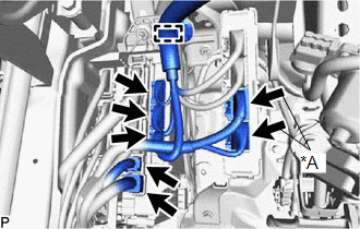
(b) Engage the clamp.
(c) Engage the clamp.
(d) Engage the claw and guide to install the instrument panel junction block assembly with main body ECU.
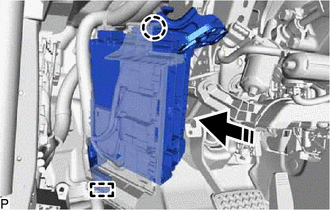
|
|
Install in this Direction |
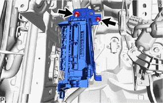
(e) for Gasoline Model:
(1) Install the 2 nuts.
Torque:
8.0 N·m {82 kgf·cm, 71 in·lbf}
(f) for HV Model:
(1) Install the 2 nuts and bolt.
Torque:
8.0 N·m {82 kgf·cm, 71 in·lbf}
(g) Connect the 2 connectors and raise the 2 lock levers to engage the 2 claws and lock the connector as shown in the illustration.
NOTICE:
Be sure to connect the connector securely.
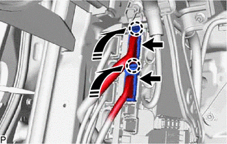
|
| Install in this Direction |
(h) Engage the clamp.
(i) Connect each connector.
4. INSTALL NO. 3 INSTRUMENT PANEL TO COWL BRACE SUB-ASSEMBLY
Click here
5. INSTALL LOWER NO. 1 INSTRUMENT PANEL AIRBAG ASSEMBLY
Click here
REMOVAL
CAUTION / NOTICE / HINT
The necessary procedures (adjustment, calibration, initialization, or registration) that must be performed after parts are removed and installed, or replaced during main body ECU (multiplex network body ECU) removal/installation are shown below.
Necessary Procedure After Parts Removed/Installed/Replaced (for Gasoline Model)|
Replaced Part or Performed Procedure |
Necessary Procedure | Effect/Inoperative Function when Necessary Procedure not Performed |
Link |
|---|---|---|---|
|
*: When performing learning using the Techstream.
Click here | |||
|
Disconnect cable from negative battery terminal |
Perform steering sensor zero point calibration |
Lane departure alert system (w/ Steering Control) |
|
|
Pre-collision system | |||
|
Intelligent clearance sonar system* | |||
|
Lighting system (for Gasoline Model with Cornering Light) | |||
|
Memorize steering angle neutral point |
Parking assist monitor system |
| |
|
Panoramic view monitor system |
| ||
|
Main body ECU (multiplex network body ECU) |
Code registration (Smart key System (for Start Function) |
|
|
CAUTION:
Some of these service operations affect the SRS airbag system. Read the precautionary notices concerning the SRS airbag system before servicing.
Click here

 Necessary Procedure After Parts Removed/Installed/Replaced (for HV Model)
 |
Replaced Part or Performed Procedure |
Necessary Procedure | Effect/Inoperative Function When Necessary Procedures are not Performed |
Link |
|---|---|---|---|
|
*: When performing learning using the Techstream.
Click here | |||
|
Disconnect cable from negative auxiliary battery terminal |
Perform steering sensor zero point calibration |
Lane departure alert system (w/ Steering Control) |
|
|
Pre-collision system | |||
|
Intelligent clearance sonar system* | |||
|
Lighting system (for HV Model with Cornering Light) | |||
|
Memorize steering angle neutral point |
Parking assist monitor system |
| |
|
Panoramic view monitor system |
| ||
|
Main body ECU (multiplex network body ECU) |
Code registration (Smart key System (for Start Function) |
|
|
CAUTION:
Some of these service operations affect the SRS airbag system. Read the precautionary notices concerning the SRS airbag system before servicing.
Click here
PROCEDURE
1. REMOVE LOWER NO. 1 INSTRUMENT PANEL AIRBAG ASSEMBLY
Click here
2. REMOVE NO. 3 INSTRUMENT PANEL TO COWL BRACE SUB-ASSEMBLY
Click here
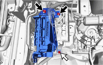
3. REMOVE INSTRUMENT PANEL JUNCTION BLOCK ASSEMBLY WITH MAIN BODY ECU
| (a) Disconnect each connector. |
|
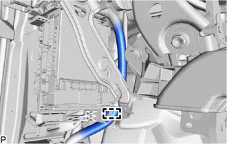
(b) Disengage the clamp.
(c) Disengage the 2 claws and pull down the 2 lock levers to disconnect the 2 connectors as shown in the illustration.
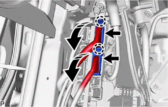
 | Remove in this Direction |
| (d) Disconnect each connector. |
|
(e) for Gasoline Model:
|
(1) Remove the 2 nuts. |
|
(f) for HV Model:
(1) Remove the 2 nuts and bolt.
 |
Nut |
 |
Bolt |
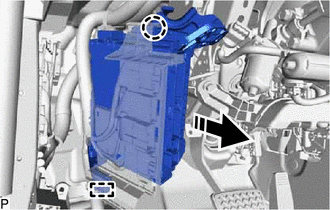
(g) Disengage the claw, guide and pull out the instrument panel junction block assembly with main body ECU.
|
|
Remove in this Direction |
| (h) Disengage the clamp. |
|
| (i) Disengage the clamp. |
|
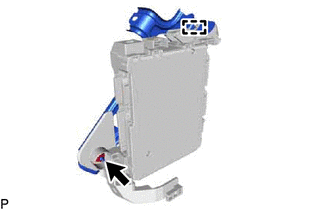
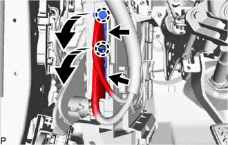
(j) Disengage the 2 claws and pull down the 2 lock levers to disconnect the 2 connectors as shown in the illustration and remove the instrument panel junction block assembly with main body ECU.
|
| Remove in this Direction |
4. REMOVE WIRING HARNESS CLAMP BRACKET
| (a) Remove the nut. |
|
(b) Disengage the guide to remove the wiring harness clamp bracket.
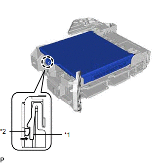
5. REMOVE MAIN BODY ECU (MULTIPLEX NETWORK BODY ECU)
(a) Press the claw of the instrument panel junction block assembly as shown in the illustration to release the lock.
|
*1 | Instrument Panel Junction Block Assembly |
|
*2 | Main Body ECU (Multiplex Network Body ECU) |
|
|
Press in this Direction |
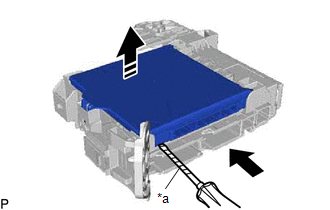
(b) With the instrument panel junction block assembly lock released, insert a screwdriver with its tip wrapped with protective tape horizontally between the main body ECU (multiplex network body ECU) and junction block assembly.
|
*a | Protective Tape |
|
|
Insert in this Direction |
|
|
Remove in this Direction |
NOTICE:
(c) Using the screwdriver, carefully raise the main body ECU (multiplex network body ECU) to the position where the connector becomes disconnected.
NOTICE:
Do not twist the screwdriver to raise the main body ECU (multiplex network body ECU).
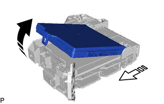
(d) Raise the main body ECU (multiplex network body ECU) as shown by the arrow (1), and then pull it out as shown by the arrow (2) in the illustration.
|
| Remove in this Direction (1) |
 | Remove in this Direction (2) |
NOTICE:
Do not touch the main body ECU (multiplex network body ECU) connector.
Toyota Avalon (XX50) 2019-2022 Service & Repair Manual > Hybrid Control System: Collision detected or Collision Sensor Connection (Open) (P160600,P160604). Throttle/Pedal Position Sensor/Switch "D" Circuit Short to Auxiliary Battery (P212012,...,P21382B). IG2 Signal Circuit Short
Collision detected or Collision Sensor Connection (Open) (P160600,P160604) DTC SUMMARY MALFUNCTION DESCRIPTION The hybrid vehicle control ECU and airbag ECU assembly detect that a collision has occurred and shut off the system main relay. The cause of this DTC may be one of the following: Collision ...