DESCRIPTION
While torque sensor system, motor system or ECU system malfunctions are detected, the fail-safe function suspends power assist. However, power assist continues with limited assistance amount if only C1533 or C1534 is output.
|
DTC No. | Detection Item |
DTC Detection Condition | Trouble Area |
Warning Indicate | Return-to-normal Condition |
Note |
|---|---|---|---|---|---|---|
| C1511 |
Torque Sensor1 | Torque sensor malfunction |
Rack and pinion power steering gear assembly |
EPS warning light: Comes on |
Engine switch on (IG) again |
- |
| C1512 |
Torque Sensor2 | Torque sensor malfunction |
Rack and pinion power steering gear assembly |
EPS warning light: Comes on |
Engine switch on (IG) again |
- |
| C1513 |
Torque Sensor Deviation Excessive |
Torque sensor malfunction |
Rack and pinion power steering gear assembly |
EPS warning light: Comes on |
Engine switch on (IG) again |
- |
| C1514 |
Torque Sensor Power Supply Voltage |
Torque sensor malfunction |
Rack and pinion power steering gear assembly |
EPS warning light: Comes on |
Engine switch on (IG) again |
- |
| C1517 |
Torque Hold | Torque sensor malfunction |
Rack and pinion power steering gear assembly |
EPS warning light: Comes on |
Engine switch on (IG) again |
- |
| C1521 |
Short in Motor Circuit |
Motor overcurrent | Rack and pinion power steering gear assembly |
EPS warning light: Comes on |
Engine switch on (IG) again |
- |
| C1522 |
Power Supply Sensor | Motor current sensor malfunction |
Rack and pinion power steering gear assembly |
EPS warning light: Comes on |
Engine switch on (IG) again |
- |
| C1523 |
Current Deviation Excessive |
Excessively large current deviation |
Rack and pinion power steering gear assembly |
EPS warning light: Comes on |
Engine switch on (IG) again |
- |
| C1528 |
Motor Rotation Angle Sensor |
Motor rotation angle sensor malfunction |
Rack and pinion power steering gear assembly |
EPS warning light: Comes on |
Engine switch on (IG) again |
- |
| C1531 |
ECU Malfunction | ECU internal malfunction (CPU malfunction) |
Rack and pinion power steering gear assembly |
EPS warning light: Comes on |
Engine switch on (IG) again |
- |
| C1532 |
ECU Malfunction | ECU internal malfunction (Peripheral circuit malfunction) |
Rack and pinion power steering gear assembly |
EPS warning light: Comes on |
Engine switch on (IG) again |
- |
| C1533 |
Temperature Sensor Circuit is Low or High |
ECU internal malfunction (Substrate temperature sensor malfunction) |
Rack and pinion power steering gear assembly |
EPS warning light: Comes on |
The ECU judges the system has returned to normal |
- |
| C1534 |
EEPROM | ECU internal malfunction (EEPROM error) |
Rack and pinion power steering gear assembly |
EPS warning light: Comes on |
Engine switch on (IG) again |
- |
| C1555 |
Motor Relay Welding Failure |
Motor relay circuit malfunction |
Rack and pinion power steering gear assembly |
EPS warning light: Comes on |
Engine switch on (IG) again |
- |
CAUTION / NOTICE / HINT
NOTICE:
If the rack and pinion power steering gear assembly has been replaced, perform assist map writing and torque sensor zero point calibration.
Click here

PROCEDURE
| 1. |
CHECK FOR DTC |
(a) Clear the DTCs.
Chassis > EMPS > Clear DTCs(b) Check for DTCs.
Chassis > EMPS > Trouble Codes|
Result | Proceed to |
|---|---|
|
DTCs other than C1511, C1512, C1513, C1514, C1517, C1521, C1522, C1523, C1528, C1531, C1532, C1533, C1534 or C1555 are not output. |
A |
| DTCs other than C1511, C1512, C1513, C1514, C1517, C1521, C1522, C1523, C1528, C1531, C1532, C1533, C1534 or C1555 are output. |
B |
| DTCs are not output. |
C |
| A |
 | REPLACE RACK AND PINION POWER STEERING GEAR ASSEMBLY |
| B |
| GO TO DIAGNOSTIC TROUBLE CODE CHART |
| C |
| USE SIMULATION METHOD TO CHECK |
DESCRIPTION
This DTC does not indicate a malfunction. The power steering ECU (rack and pinion power steering gear assembly) stores this DTC when it determines that torque sensor zero point calibration has not been performed.
When the IG terminal voltage is below 8 V, torque sensor zero point calibration cannot be performed.
|
DTC No. | Detection Item |
DTC Detection Condition | Trouble Area |
Warning Indicate | Return-to-normal Condition |
Note |
|---|---|---|---|---|---|---|
| C1515 |
Torque Sensor Zero Point Adjustment Undone |
This DTC is stored when torque sensor zero point calibration has not been performed. |
Torque sensor zero point calibration |
EPS warning light: Comes on |
Zero point calibration is performed or the engine switch on (IG) again |
There is no malfunction if this DTC is not output again after performing zero point calibration. |
CAUTION / NOTICE / HINT
NOTICE:
If the rack and pinion power steering gear assembly has been replaced, perform assist map writing and torque sensor zero point calibration.
Click here

PROCEDURE
| 1. |
CHECK FOR DTC |
(a) Calibrate the torque sensor zero point. (Step 1)
Chassis > EMPS > Utility|
Tester Display |
|---|
| Torque Sensor Adjustment |
(b) Check for DTCs. (Step 2)
Chassis > EMPS > Trouble CodesHINT:
If DTCs are output, perform steps (1) and (2) two more times.
|
Result | Proceed to |
|---|---|
|
DTCs are still output after performing steering zero point calibration 3 times. |
A |
| Normal system code is output. |
B |
| A |
 | REPLACE RACK AND PINION POWER STEERING GEAR ASSEMBLY |
| B |
| END |
DESCRIPTION
This DTC does not indicate a malfunction. The power steering ECU (rack and pinion power steering gear assembly) stores this DTC when it determines that torque sensor zero point calibration has not completed.
|
DTC No. | Detection Item |
DTC Detection Condition | Trouble Area |
Warning Indicate | Return-to-normal Condition |
Note |
|---|---|---|---|---|---|---|
| C1516 |
Torque Sensor Zero Point Adjustment Incomplete |
Torque sensor zero point calibration is incomplete due to the steering wheel being touched during calibration. |
Torque sensor zero point calibration |
EPS warning light: Comes on |
The DTC is cleared | There is no malfunction if this DTC is not output again after clearing the DTC and torque sensor calibration value, and performing zero point calibration. |
CAUTION / NOTICE / HINT
NOTICE:
If the rack and pinion power steering gear assembly has been replaced, perform assist map writing and torque sensor zero point calibration.
Click here

PROCEDURE
| 1. |
REPLACE CHECK FOR DTC |
(a) Clear the DTCs. (Step 1)
Chassis > EMPS > Clear DTCs(b) Calibrate the torque sensor zero point. (Step 2)
Chassis > EMPS > Utility|
Tester Display |
|---|
| Torque Sensor Adjustment |
(c) Check for DTCs. (Step 3)
Chassis > EMPS > Trouble CodesHINT:
If DTCs are output, perform steps (1) to (3) two more times.
|
Result | Proceed to |
|---|---|
|
DTCs are still output after performing steering zero point calibration 3 times. |
A |
| Normal system code is output. |
B |
| A |
 | REPLACE RACK AND PINION POWER STEERING GEAR ASSEMBLY |
| B |
| END |
DESCRIPTION
The power steering ECU (rack and pinion power steering gear assembly) receives vehicle speed signals from the skid control ECU (brake actuator assembly) via CAN communication. The ECU provides appropriate assist force in accordance with the vehicle speed based on the signals.
|
DTC No. | Detection Item |
DTC Detection Condition | Trouble Area |
Warning Indicate | Return-to-normal Condition |
Note |
|---|---|---|---|---|---|---|
| C1541 |
Vehicle Speed Signal | A vehicle speed signal malfunction is detected |
| EPS warning light: Comes on |
The ECU judges the system has returned to normal |
- |
CAUTION / NOTICE / HINT
NOTICE:
If the rack and pinion power steering gear assembly has been replaced, perform assist map writing and torque sensor zero point calibration.
Click here

PROCEDURE
| 1. |
CHECK CAN COMMUNICATION SYSTEM |
(a) Check if DTC U0129 is output.
Chassis > EMPS > Trouble Codes|
Result | Proceed to |
|---|---|
|
DTC U0129 is not output. |
A |
| DTC U0129 is output. |
B |
| A |
 | GO TO BRAKE CONTROL SYSTEM (DIAGNOSTIC TROUBLE CODE CHART) |
| B |
| GO TO CAN COMMUNICATION SYSTEM (HOW TO PROCEED WITH TROUBLESHOOTING) |
DESCRIPTION
When a malfunction is detected in the power source circuit, the fail-safe function suspends power assist.
|
DTC No. | Detection Item |
DTC Detection Condition | Trouble Area |
Warning Indicate | Return-to-normal Condition |
Note |
|---|---|---|---|---|---|---|
| C1551 |
IG Power Supply Voltage |
When the PIG power supply voltage is normal, the IG power supply voltage is 18.5 V or higher |
| EPS warning light: Comes on |
The ECU judges the system has returned to normal |
- |
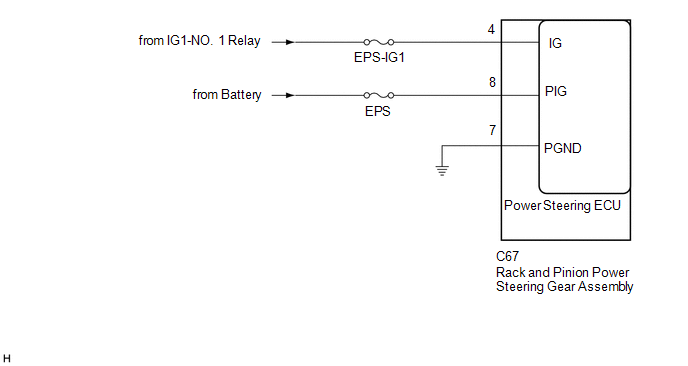
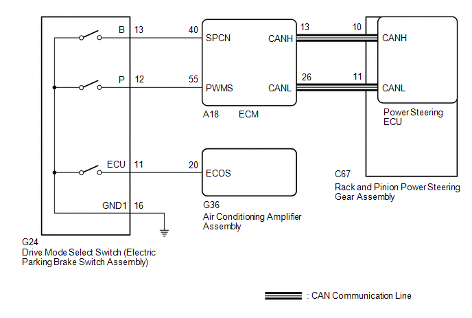
WIRING DIAGRAM
CAUTION / NOTICE / HINT
NOTICE:
Click here 
PROCEDURE
|
1. | CHECK HARNESS AND CONNECTOR (BATTERY - RACK AND PINION POWER STEERING GEAR ASSEMBLY) |
(a) Disconnect the C67 rack and pinion power steering gear assembly connector.

|
*a | Front view of wire harness connector (to Rack and Pinion Power Steering Gear Assembly) |
- | - |
(b) Measure the voltage according to the value(s) in the table below.
Standard Voltage:
|
Tester Connection | Condition |
Specified Condition |
|---|---|---|
|
C67-4 (IG) - Body ground |
Engine switch on (IG) |
Below 18.5 V |
| NG |  | REPAIR OR REPLACE HARNESS OR CONNECTOR |
|
| 2. |
CHECK FOR DTC |
(a) Clear the DTCs.
Chassis > EMPS > Clear DTCs(b) Check for DTCs.
Chassis > EMPS > Trouble Codes|
Result | Proceed to |
|---|---|
|
DTC is output. | A |
|
DTC is not output. | B |
| A |
| REPLACE RACK AND PINION POWER STEERING GEAR ASSEMBLY |
| B |
| USE SIMULATION METHOD TO CHECK |
DESCRIPTION
When a malfunction is detected in the PIG power source and power supply relay system, the fail-safe function suspends power assist.
|
DTC No. | Detection Item |
DTC Detection Condition | Trouble Area |
Warning Indicate | Return-to-normal Condition |
Note |
|---|---|---|---|---|---|---|
| C1552 |
PIG Power Supply Voltage |
PIG power source circuit malfunction |
| EPS warning light: Comes on |
Engine switch on (IG) again |
- |
| C1554 |
Power Supply Relay Failure |
Power source relay circuit malfunction |
| EPS warning light: Comes on |
Engine switch on (IG) again |
- |
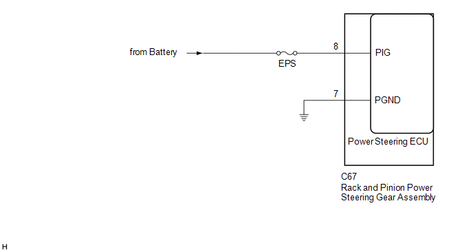
WIRING DIAGRAM
CAUTION / NOTICE / HINT
NOTICE:
Click here 
PROCEDURE
|
1. | CHECK HARNESS AND CONNECTOR (RACK AND PINION POWER STEERING GEAR ASSEMBLY - BODY GROUND) |
(a) Disconnect the C67 rack and pinion power steering gear assembly connector.

|
*a | Front view of wire harness connector (to Rack and Pinion Power Steering Gear Assembly) |
- | - |
(b) Measure the voltage according to the value(s) in the table below.
Standard Voltage:
|
Tester Connection | Condition |
Specified Condition |
|---|---|---|
|
C67-8 (PIG) - Body ground |
Always | 9 to 16 V |
(c) Measure the resistance according to the value(s) in the table below.
Standard Resistance:
|
Tester Connection | Condition |
Specified Condition |
|---|---|---|
|
C67-7 (PGND) - Body ground |
Always | Below 1 Ω |
| OK |  | REPLACE RACK AND PINION POWER STEERING GEAR ASSEMBLY |
| NG | | REPAIR OR REPLACE HARNESS OR CONNECTOR |
DESCRIPTION
The power steering ECU (rack and pinion power steering gear assembly) determines whether an incompatible ECM, main body ECU (multiplex network body ECU) or skid control ECU (brake actuator assembly) is installed based on the identification information.
|
DTC No. | Detection Item |
DTC Detection Condition | Trouble Area |
Warning Indicate | Return-to-normal Condition |
Note |
|---|---|---|---|---|---|---|
| C1567 |
Error in Matching of ECUs |
|
| EPS warning light: Comes on |
Engine switch on (IG) again |
- |
CAUTION / NOTICE / HINT
NOTICE:
If the rack and pinion power steering gear assembly has been replaced, perform assist map writing and torque sensor zero point calibration.
Click here

PROCEDURE
| 1. |
CHECK RELATED PART |
(a) Confirm if the related part has the correct part number.
|
Related Part | ECM |
| Main body ECU (Multiplex network body ECU) | |
|
Skid control ECU (Brake actuator assembly) |
NOTICE:
When removing the related part to check it, be sure to follow the appropriate procedures and precautions.
Click here
Click here
Click here
|
Result | Proceed to |
|---|---|
|
The related part has the correct part number. |
A |
| The related part has an incorrect part number. |
B |
| B |
 | GO TO STEP 3 |
|
| 2. |
CHECK FOR DTC |
(a) Select Health Check on the Techstream screen and check if system DTCs of the related part are output.
HINT:
If system DTCs of the related part are stored, assist map writing to the power steering ECU (rack and pinion power steering gear assembly) may not be performed properly.
|
Result | Proceed to |
|---|---|
|
System DTCs of the related part are output. |
A |
| System DTCs of the related part are not output. |
B |
| A |
| REPAIR CIRCUIT INDICATED BY OUTPUT CODE |
| B |
| REPLACE RACK AND PINION POWER STEERING GEAR ASSEMBLY |
| 3. |
REPLACE RELATED PART WITH PART THAT HAS CORRECT PART NUMBER |
(a) Replace the related part with one that has the correct part number.
Click here
Click here
Click here
|
| 4. |
CHECK FOR DTC |
(a) Check for DTCs.
Chassis > EMPS > Trouble Codes|
Result | Proceed to |
|---|---|
|
DTCs are not output. |
A |
| DTCs are output. |
B |
| A |
| END |
| B |
| REPLACE RACK AND PINION POWER STEERING GEAR ASSEMBLY |
DESCRIPTION
This DTC will be stored if the power steering ECU (rack and pinion power steering gear assembly) determines that the assist map is not written in the ECU.
|
DTC No. | Detection Item |
DTC Detection Condition | Trouble Area |
Warning Indicate | Return-to-normal Condition |
Note |
|---|---|---|---|---|---|---|
| C1581 |
Assist Map Number Un-Writing |
Assist map not written in power steering ECU (rack and pinion power steering gear assembly) |
| EPS warning light: Comes on |
Assist Map Writing is performed |
- |
CAUTION / NOTICE / HINT
NOTICE:
If the rack and pinion power steering gear assembly has been replaced, perform assist map writing and torque sensor zero point calibration.
Click here

HINT:
Related parts store information necessary for assist map writing.
Related Part:
PROCEDURE
|
1. | PERFORM ASSIST MAP WRITING |
(a) Perform assist map writing.
Chassis > EMPS > Utility|
Tester Display |
|---|
| Signal Check |
(b) Check for DTCs.
Chassis > EMPS > Trouble Codes|
Result | Proceed to |
|---|---|
|
DTC C1581 is output. |
A |
| DTC C1581 is not output. |
B |
| B |
 | END |
|
| 2. |
CHECK CAN COMMUNICATION SYSTEM |
(a) Check for DTCs.
Click here
|
Result | Proceed to |
|---|---|
|
CAN communication system DTCs are not output. |
A |
| CAN communication system DTCs are output. |
B |
| B |
| GO TO CAN COMMUNICATION SYSTEM |
|
| 3. |
CHECK RELATED PART |
(a) Confirm if the related part has the correct part number.
|
Related Part | ECM |
| Main body ECU (Multiplex network body ECU) | |
|
Skid control ECU (Brake actuator assembly) | |
|
AVS ECU (Absorber control ECU) (w/ Adaptive Variable Suspension System) |
NOTICE:
When removing the related part to check it, be sure to follow the appropriate procedures and precautions.
Click here
Click here
Click here
Click here
|
Result | Proceed to |
|---|---|
|
The related part has the correct part number. |
A |
| The related part has an incorrect part number. |
B |
| B |
| GO TO STEP 5 |
|
| 4. |
CHECK FOR DTC |
(a) Select Health Check on the Techstream screen and check if system DTCs of the related part are output.
HINT:
If system DTCs of the related part are stored, assist map writing to the power steering ECU (rack and pinion power steering gear assembly) may not be performed properly.
|
Result | Proceed to |
|---|---|
|
System DTCs of the related part are output. |
A |
| System DTCs of the related part are not output. |
B |
| A |
| REPAIR CIRCUIT INDICATED BY OUTPUT CODE |
| B |
| REPLACE RACK AND PINION POWER STEERING GEAR ASSEMBLY |
| 5. |
REPLACE RELATED PART WITH PART THAT HAS CORRECT PART NUMBER |
(a) Replace the related part with one that has the correct part number.
Click here
Click here
Click here
Click here
|
| 6. |
CHECK FOR DTC |
(a) Check for DTCs.
Chassis > EMPS > Trouble Codes|
Result | Proceed to |
|---|---|
|
DTCs are not output. |
A |
| DTCs are output. |
B |
| A |
| END |
| B |
| REPLACE RACK AND PINION POWER STEERING GEAR ASSEMBLY |
DESCRIPTION
When an incorrect ECM, main body ECU (multiplex network body ECU), skid control ECU (brake actuator assembly) or AVS ECU (Absorber control ECU) (w/ Adaptive Variable Suspension System) is installed after the assist map has been written to the power steering ECU (rack and pinion power steering gear assembly), DTC C1582 is stored because the information stored in the power steering ECU (rack and pinion power steering gear assembly) does not match the vehicle specifications.
|
DTC No. | Detection Item |
DTC Detection Condition | Trouble Area |
Warning Indicate | Return-to-normal Condition |
Note |
|---|---|---|---|---|---|---|
| C1582 |
Assist Map Number Mismatch |
Assist map number mismatch |
| EPS warning light: Does not come on |
Engine switch on (IG) again |
- |
CAUTION / NOTICE / HINT
NOTICE:
If the rack and pinion power steering gear assembly has been replaced, perform assist map writing and torque sensor zero point calibration.
Click here

HINT:
Related parts store information necessary for assist map writing.
Related Part:
PROCEDURE
|
1. | CHECK CAN COMMUNICATION SYSTEM |
(a) Check for DTCs.
Click here
|
Result | Proceed to |
|---|---|
|
CAN communication system DTCs are not output. |
A |
| CAN communication system DTCs are output. |
B |
| B |
 | GO TO CAN COMMUNICATION SYSTEM |
|
| 2. |
CHECK RELATED PART |
(a) Check if the part below has been replaced with an incorrect part in the past.
|
Related Part | ECM |
| Main body ECU (Multiplex network body ECU) | |
|
Skid control ECU (Brake actuator assembly) | |
|
AVS ECU (Absorber control ECU) (w/ Adaptive Variable Suspension System) |
NOTICE:
When removing the related part to check it, be sure to follow the appropriate procedures and precautions.
Click here
Click here
Click here
Click here
(b) When DTC C1582 is output and parts have not been exchanged, replace the power steering ECU (rack and pinion power steering gear assembly) as it may have an internal malfunction.
NOTICE:
If the rack and pinion power steering gear assembly has been replaced, perform assist map writing.
Click here
|
Result | Proceed to |
|---|---|
|
The related part has an incorrect part number. |
A |
| The related part has the correct part number, or a related part and rack and pinion power steering gear assembly have not been replaced. |
B |
| B |
| REPLACE RACK AND PINION POWER STEERING GEAR ASSEMBLY |
|
| 3. |
REPLACE RELATED PART WITH PART THAT HAS CORRECT PART NUMBER |
(a) Replace the related part with one that has the correct part number.
Click here
Click here
Click here
Click here
|
| 4. |
CHECK FOR DTC |
(a) Check for DTCs.
Chassis > EMPS > Trouble Codes|
Result | Proceed to |
|---|---|
|
DTCs are not output. |
A |
| DTCs are output. |
B |
| A |
| END |
| B |
| REPLACE RACK AND PINION POWER STEERING GEAR ASSEMBLY |
CALIBRATION
TORQUE SENSOR ZERO POINT CALIBRATION (USING TECHSTREAM)
NOTICE:
Perform torque sensor zero point calibration if any of the following conditions occur:
(a) Perform inspection before calibration.
(1) Turn the engine switch off.
(2) Connect the Techstream to the DLC3.
(3) Turn the engine switch on (IG).
(4) Turn the Techstream on.
(5) Calibrate the rack and pinion power steering gear assembly. Enter the following menus: Chassis / EMPS / Data List.
(6) Read the Data List according to the display on the Techstream.
Chassis > EMPS > Data List|
Tester Display | Measurement Item |
Range | Normal Condition |
Diagnostic Note |
|---|---|---|---|---|
|
IG Power Supply | IG power source voltage |
Min.: 0.0000 V Max.: 20.1531 V |
8 to 16 V | Engine switch on (IG) |
|
Tester Display |
|---|
| IG Power Supply |
Standard Voltage:
8 to 16 V
NOTICE:
If the IG power supply voltage is 8 V or less, calibration cannot be performed. In this case, charge or replace the battery, and then perform calibration.
(b) Perform torque sensor zero point calibration.
NOTICE:
If DTC C1516 (Torque Sensor Zero Point Adjustment Incomplete) is stored, the torque sensor zero point cannot be calibrated. Clear the DTCs before starting calibration.
(1) Align the front wheels straight ahead and center the steering wheel.
(2) Turn the engine switch off.
(3) Connect the Techstream to the DLC3.
(4) Turn the engine switch on (IG).
(5) Turn the Techstream on.
(6) Enter the following menus: Chassis / EMPS / Utility / Torque Sensor Adjustment.
Chassis > EMPS > Utility|
Tester Display |
|---|
| Torque Sensor Adjustment |
NOTICE:
(7) Check for DTCs.
Chassis > EMPS > Trouble CodesNOTICE:
If DTC C1515, C1516, C1534 or C1581 is output, perform troubleshooting for the corresponding DTC.
|
Result | See Procedure |
|---|---|
|
DTC C1515 is output. |
|
|
DTC C1516 is output. |
|
|
DTC C1534 is output. |
|
|
DTC C1581 is output. |
|
ASSIST MAP WRITING (USING TECHSTREAM)
NOTICE:
Perform assist map writing if the following condition occurs:
The rack and pinion power steering gear assembly has been replaced.
(a) Turn the engine switch off.
(b) Connect the Techstream to the DLC3.
(c) Turn the engine switch on (IG).
(d) Turn the Techstream on.
(e) Enter the following menus: Chassis / EMPS / Utility / Signal Check.
Chassis > EMPS > Utility|
Tester Display |
|---|
| Signal Check |
HINT:
(f) Wait for at least 5 seconds.
(g) Check for DTCs.
Chassis > EMPS > Trouble CodesHINT:
After writing the assist map, if DTC C1581 is output, perform the troubleshooting procedure for DTC C1581.
Click here 
CAUTION / NOTICE / HINT
HINT:
Perform this troubleshooting procedure when no DTCs are output, including DTCs related to CAN communication system malfunctions.
PROCEDURE
| 1. |
READ VALUE USING TECHSTREAM (ASSIST LIMIT RECORD 1) |
(a) Using the Techstream, read the Data List item "Assist Limit Record 1".
Click here 
|
Tester Display | Measurement Item |
Range | Normal Condition |
Diagnostic Note |
|---|---|---|---|---|
|
Assist Limit Record 1 | Information of assist limit that was used in the past or is currently in use (latest history) |
Unrec, Mtr Overheat, Pow Vol Low, Pow Vol Low Prevent, Eng Stall, Ready OFF, Mtr Overload, DC-DC Malf, Vhcl Spd Sig Malf, Batt Vol Keep |
- | - |
HINT:
For the Data List item "Assist Limit Record 1", each item in the Range is described below.
|
Range | Description |
Diagnostic Note | |
|---|---|---|---|
|
Assist Limit Record 1 | Unrec |
No assist limit. Continue with troubleshooting for "Heavy steering". |
- |
| Mtr Overheat |
When the vehicle is stopped or traveling at low speed, and steering operations are performed repeatedly or the steering wheel is turned all the way to the side and held there for a long time, assist may be limited in order to prevent overheating of the power steering motor assembly and power steering ECU assembly. After 10 minutes elapse with the engine running and no steering operations being performed, the system will return to normal. After recovering from the overheated condition, assist can be performed as usual. |
- | |
| Pow Vol Low |
When insufficient battery charge, or battery degradation etc. causes the voltage to temporarily decrease, assist may be stopped. After the battery condition returns to normal, assist can be performed as usual. |
- | |
| Pow Vol Low Prevent |
When insufficient battery charge, or battery degradation etc. causes the voltage to temporarily decrease, assist may be limited. After the battery condition returns to normal, assist can be performed as usual. |
- | |
| Eng Stall |
When the engine stalls, battery charge becomes insufficient, so assist is stopped. After recovering from the engine stall, assist can be performed as usual. |
- | |
| Ready OFF |
After Ready ON, if a malfunction in the HV system etc. causes a return to Ready OFF, the HV battery charge becomes insufficient, so assist is stopped. After returning to Ready ON state, assist can be performed as usual. |
Not displayed for this vehicle | |
|
Mtr Overload | When the steering wheel cannot turn, such as when a road wheel is against a curb, if the driver continues to apply force to the steering wheel, current to the motor may be limited to prevent overheating. When the steering wheel is returned to a neutral position, assist can be performed as usual. |
- | |
| DC-DC Malf |
If there is a malfunction in the DC-DC converter, etc., assist may be limited. After the DC-DC converter returns to normal, assist can be performed as usual. |
Not displayed for this vehicle | |
|
Vhcl Spd Sig Malf | If the vehicle speed signal is abnormal due to a wheel speed sensor malfunction, etc., assist may be limited. |
- | |
| Batt Vol Keep |
When insufficient battery charge, or battery degradation etc. causes the voltage to temporarily decrease, assist may be limited. After the battery condition returns to normal, assist can be performed as usual. |
- |
|
Tester Display |
|---|
| Assist Limit Record 1 |
(b) Based on the "Assist Limit Record 1" information, the following Data List items and the information from the customer interview, explain the situation to the customer.
Chassis > EMPS > Data List|
Tester Display |
|---|
| Record 1 Key Cycle |
|
Record 1 Key Cycle Elapsed Time |
HINT:
If it is necessary to investigate further into the past, check the "Assist Limit Record 2" and "Assist Limit Record 3" information in the same way as "Assist Limit Record 1".
| NEXT |  |
END |
CUSTOMIZE PARAMETERS
DRIVE MODE CUSTOMIZATION (w/ Adaptive Variable Suspension System)
When the drive mode is switched to "CUSTOM" mode using the drive mode select switch (electric parking brake switch assembly), the vehicle settings can be changed on the multi-display.
HINT:
Differing to that of "ECO", "SPORT S" and "SPORT S+", when "CUSTOM" is selected using the drive mode select switch (electric parking brake switch assembly), "Powertrain", "Chassis" and "Climate" settings can be changed.
(a) Turn the engine switch on (IG).
(b) Select the following menus on the multi-display to enter the customize setting screen: Setup / Vehicle / Drive Mode Customization
Drive Mode Customization|
Display | Content |
Default | Setting |
|---|---|---|---|
|
Powertrain | Acceleration response, etc. |
Normal | Power / Normal / Eco |
|
Chassis | Damping force of suspension, steering assist force, etc. |
Normal | Sport / Normal |
|
Climate | Effectiveness of air conditioning system, etc. |
Normal | Normal / Eco |
DATA LIST / ACTIVE TEST
DATA LIST
HINT:
Using the Techstream to read the Data List allows the values or states of switches, sensors, actuators and other items to be read without removing any parts. This non-intrusive inspection can be very useful because intermittent conditions or signals may be discovered before parts or wiring is disturbed. Reading the Data List information early in troubleshooting is one way to save diagnostic time.
NOTICE:
In the table below, the values listed under "Normal Condition" are reference values. Do not depend solely on these reference values when deciding whether a part is faulty or not.
(a) Turn the engine switch off.
(b) Connect the Techstream to the DLC3.
(c) Turn the engine switch on (IG).
(d) Turn the Techstream on.
(e) Enter the following menus: Chassis / EMPS / Data List.
(f) Read the Data List according to the display on the Techstream.
Chassis > EMPS > Data List|
Tester Display | Measurement Item |
Range | Normal Condition |
Diagnostic Note |
|---|---|---|---|---|
|
Meter Vehicle Velocity |
Vehicle speed from speedometer |
Min.: 0.0 km/h (0.0 MPH) Max.: 300.0 km/h (186.4 MPH) |
| - |
|
Wheel Speed Right | Rear right wheel speed |
Min.: 0 km/h (0 MPH) Max.: 255 km/h (158 MPH) |
| - |
|
Wheel Speed Left | Rear left wheel speed |
Min.: 0 km/h (0 MPH) Max.: 255 km/h (158 MPH) |
| - |
|
Engine Revolution | Engine speed |
Min.: 0 rpm Max.: 12800 rpm |
No significant fluctuation |
Engine running at a constant speed |
|
Motor Actual Current | Amount of current to motor |
Min.: -327.68 A Max.: 327.67 A |
Value changes in proportion to steering effort - The value increases when turning right and decreases when turning left |
Engine running and steering wheel being turned |
|
Command Value Current | Requested current to motor |
Min.: -327.68 A Max.: 327.67 A |
Value changes in proportion to steering effort - The value increases when turning right and decreases when turning left |
Engine running and steering wheel being turned |
|
Steering Angle Velocity |
Steering angle speed | Min.: -32768 deg/s Max.: 32767 deg/s | Value changes in proportion to steering speed - The value increases when turning left and decreases when turning right |
Engine running and steering wheel being turned |
|
Thermistor Temperature |
ECU substrate temperature |
Min.: -50.0°C (-58.0°F) Max.: 150.0°C (302.0°F) |
-50°C to 150°C (-58°F to 302°F) |
- |
| IG Power Supply |
IG power source voltage |
Min.: 0.0000 V Max.: 20.1531 V |
8 to 16 V | Engine switch on (IG) |
|
Steering Angle Sens Sig |
Steering sensor signal state |
OK or NG(1) or NG(2) or NG(3) |
OK: Steering sensor signal received NG(1): The learning has not completed NG(2): Steering sensor abnormal NG(3): Communication error |
- |
| Steering Wheel Torque |
Steering wheel torque | Min.: -327.68 Nm Max.: 7.00 Nm | Value changes in proportion to steering effort - The value increases when turning left and decreases when turning right |
Engine running and steering wheel being turned |
|
Motor Rotation Angle | Motor rotation angle |
Min.: 0.000 deg Max.: 1441.770 deg |
During steering operation, motor rotation angle value changes from 0 to 360° |
Engine running and steering wheel being turned |
|
Command Val Current 2 | Requested current to motor |
Min.: -327.68 A Max.: 327.67 A |
Value changes in proportion to steering effort |
Engine running and steering wheel being turned |
|
Motor Voltage | Motor power supply voltage |
Min.: 0.000 V Max.: 98.000 V |
| - |
|
TRQ1 Zero Point Value | Zero point value of torque sensor 1 |
Min.: 0.0000 V Max.: 4.9725 V |
2.3 to 2.7 V | Engine running and steering wheel not being turned (without load) |
|
TRQ2 Zero Point Value | Zero point value of torque sensor 2 |
Min.: 0.0000 V Max.: 4.9725 V |
2.3 to 2.7 V | Engine running and steering wheel not being turned (without load) |
|
IG ON/OFF Times | Number of times of engine switch turned on/off since latest DTC detection |
Min.: 0 times Max.: 65535 times |
- | - |
|
Motor Overheat Record | Continuous overheat prevention control record |
Unrec or Rec | Unrec |
Unrec: Unrecorded Rec: Recorded The amount of power assist may be decreased to prevent the motor and ECUs from overheating if the steering wheel is continuously turned when the vehicle is either stopped or driven at a low speed, or if the steering wheel is kept in either full lock position for a long time. |
|
Motor Lo Power Record | PIG power source voltage drop record |
Unrec or Rec | Unrec |
Unrec: Unrecorded Rec: Recorded If the PIG power source voltage decreases temporarily, the amount of power assist will be reduced. |
|
Eng Rev Inter Record | Record of engine signal interruption |
Unrec or Rec | Unrec |
Unrec: Unrecorded Rec: Recorded |
|
Str Angle Inter Record |
Record of steering sensor signal interruption occurrence display |
Unrec or Rec | Unrec |
Unrec: Unrecorded Rec: Recorded |
|
Spd Sig Invalid Record |
Record of vehicle speed signal invalid |
Unrec or Rec | Unrec |
Unrec: Unrecorded Rec: Recorded |
|
Battery Voltage Lo Record |
Battery voltage reduction history |
Min.: 0 times Max.: 65535 times |
0 to 65535 times | - |
|
Battery Control Count (Body ECU) |
Number of battery load control operations |
Min.: 0 times Max.: 65535 times |
- | - |
|
PS Assist Signal | Status of the record of power steering assist signal |
OFF or ON | OFF: Engine switch on (IG) ON: Engine running | - |
|
Motor Actual Current 2 |
Amount of current to motor |
Min.: -327.68 A Max.: 327.67 A |
Value changes in proportion to steering effort |
Engine running and steering wheel being turned |
|
Rotation Angle Sens Avg(SIN) |
Rotation angle sensor average (SIN) |
Min.: 0.0000 V Max.: 4.9725 V |
- | - |
|
Rotation Angle Sens Avg(COS) |
Rotation angle sensor average (COS) |
Min.: 0.0000 V Max.: 4.9725 V |
- | - |
|
Motor Overheat Limit Cnt(Normal) |
Number of times that assist limit was performed according to the estimated temperature of the motor coil and heat generating components of the power steering ECU assembly | Min.: 0 times Max.: 255 times | - |
- |
| Assist Limit Cnt(Power Voltage Low) |
Number of times that assist limit was performed due to battery voltage having dropped to 9 V or below |
Min.: 0 times Max.: 255 times |
- | - |
|
Power Vol Low Prevention Limit Cnt |
Number of times that assist limit was performed due to battery voltage having dropped to 9.7 V or below |
Min.: 0 times Max.: 255 times |
- | - |
|
Eng Stall/Ready OFF Cnt |
Number of times that assist limit was performed after the engine stalled and the engine switch was turned off |
Min.: 0 times Max.: 255 times |
- | - |
|
Motor Overheat Limit Cnt(Motor Overload) |
Number of times that assist limit was performed to prevent the system from overheating when the motor was overloaded due to the steering wheel being turned to the full lock position or a tire hitting a curb |
Min.: 0 times Max.: 255 times |
- | - |
|
Assist Limit Cnt(Vehicle Spd Sig Malf) |
Number of times that assist limit was performed due to battery voltage having dropped to 9 V or below |
Min.: 0 times Max.: 255 times |
- | - |
|
Battery Voltage Keep Limit Cnt |
Number of times that assist limit was performed due to battery voltage having dropped to 9.7 V or below |
Min.: 0 times Max.: 255 times |
- | - |
|
Assist Limit Record 1 | Information of assist limit that was used in the past or is currently in use (latest history) |
Unrec, Mtr Overheat, Pow Vol Low, Pow Vol Low Prevent, Eng Stall, Ready OFF, Mtr Overload, Vhcl Spd Sig Malf, Batt Vol Keep |
- | - |
|
Record 1 Key Cycle | Number of times that the engine switch was turned to ON before Assist Limit Record 1 was stored |
Min.: 0 times Max.: 65535 times |
- | - |
|
Record 1 Key Cycle Elapsed Time |
Period of time that elapsed since the engine switch was turned to ON before Assist Limit Record 1 was stored |
Min.: 0.0 s Max.: 53687091.1 s |
- | - |
|
Record 1 Power Source | Power source operating status when Assist Limit Record 1 was stored |
No Data, Running, Stop |
- | - |
|
Assist Limit Record 2 | Information of assist limit that was used in the past (second latest history) |
Unrec, Mtr Overheat, Pow Vol Low, Pow Vol Low Prevent, Eng Stall, Ready OFF, Mtr Overload, Vhcl Spd Sig Malf, Batt Vol Keep |
- | - |
|
Record 2 Key Cycle | Number of times that the engine switch was turned to ON after Assist Limit Record 2 was stored before Assist Limit Record 1 was stored |
Min.: 0 times Max.: 65535 times |
- | - |
|
Record 2 Key Cycle Elapsed Time |
Period of time that elapsed since the engine switch was turned to ON before Assist Limit Record 2 was stored |
Min.: 0.0 s Max.: 53687091.1 s |
- | - |
|
Record 2 Power Source | Power source operating status when Assist Limit Record 2 was stored |
No Data, Running, Stop |
- | - |
|
Assist Limit Record 3 | Information of assist limit that was used in the past (third latest history) |
Unrec, Mtr Overheat, Pow Vol Low, Pow Vol Low Prevent, Eng Stall, Ready OFF, Mtr Overload, Vhcl Spd Sig Malf, Batt Vol Keep |
- | - |
|
Record 3 Key Cycle | Number of times that the engine switch was turned to ON after Assist Limit Record 3 was stored before Assist Limit Record 2 was stored |
Min.: 0 times Max.: 65535 times |
- | - |
|
Record 3 Key Cycle Elapsed Time |
Period of time that elapsed since the engine switch was turned to ON before Assist Limit Record 3 was stored |
Min.: 0.0 s Max.: 53687091.1 s |
- | - |
|
Record 3 Power Source | Power source operating status when Assist Limit Record 3 was stored |
No Data, Running, Stop |
- | - |
|
Current Key Cycle | Number of times that engine switch was turned to ON |
Min.: 0 times Max.: 65535 times |
- | - |
|
Current Key Cycle Elapsed Time |
Time elapsed since engine switch was turned to ON |
Min.: 0.0 s Max.: 53687091.1 s |
- | - |
|
Steering Angle | Steering angle |
Min.: -3072.0 deg Max.: 3070.5 deg |
- | - |
|
Torque Sensor 1 Output |
Torque sensor 1 output value |
Min.: 0.0000 V Max.: 4.9725 V |
- | - |
|
Torque Sensor 2 Output |
Torque sensor 2 output value |
Min.: 0.0000 V Max.: 4.9725 V |
- | - |
|
Torque Sensor 1 Power Supply |
Torque sensor 1 power supply voltage |
Min.: 0.0000 V Max.: 4.9725 V |
- | - |
|
Torque Sensor 2 Power Supply |
Torque sensor 2 power supply voltage |
Min.: 0.0000 V Max.: 4.9725 V |
- | - |
|
Rotation Angle Sensor Output 1 |
Rotation angle sensor Vx1 output voltage |
Min.: 0.0000 V Max.: 4.9725 V |
- | - |
|
Rotation Angle Sensor Output 2 |
Rotation angle sensor Vx2 output voltage |
Min.: 0.0000 V Max.: 4.9725 V |
- | - |
|
Rotation Angle Sensor Output 3 |
Rotation angle sensor Vy1 output voltage |
Min.: 0.0000 V Max.: 4.9725 V |
- | - |
|
Rotation Angle Sensor Output 4 |
Rotation angle sensor Vy2 output voltage |
Min.: 0.0000 V Max.: 4.9725 V |
- | - |
|
Motor 1 Terminal Current (U) |
Motor 1 terminal current (U phase) |
Min.: -327.68 A Max.: 327.67 A |
Value changes in proportion to steering effort |
Engine running and steering wheel being turned |
|
Motor 1 Terminal Current (V) |
Motor 1 terminal current (V phase) |
Min.: -327.68 A Max.: 327.67 A |
Value changes in proportion to steering effort |
Engine running and steering wheel being turned |
|
Motor 1 Terminal Current (W) |
Motor 1 terminal current (W phase) |
Min.: -327.68 A Max.: 327.67 A |
Value changes in proportion to steering effort |
Engine running and steering wheel being turned |
|
Motor 2 Terminal Current (U) |
Motor 2 terminal current (U phase) |
Min.: -327.68 A Max.: 327.67 A |
Value changes in proportion to steering effort |
Engine running and steering wheel being turned |
|
Motor 2 Terminal Current (V) |
Motor 2 terminal current (V phase) |
Min.: -327.68 A Max.: 327.67 A |
Value changes in proportion to steering effort |
Engine running and steering wheel being turned |
|
Motor 2 Terminal Current (W) |
Motor 2 terminal current (W phase) |
Min.: -327.68 A Max.: 327.67 A |
Value changes in proportion to steering effort |
Engine running and steering wheel being turned |
|
Motor 1 U Phase Duty | Motor 1 U phase duty |
Min.: 0.00% Max.: 100.00% |
- | - |
|
Motor 1 V Phase Duty | Motor 1 V phase duty |
Min.: 0.00% Max.: 100.00% |
- | - |
|
Motor 1 W Phase Duty | Motor 1 W phase duty |
Min.: 0.00% Max.: 100.00% |
- | - |
|
Motor 2 U Phase Duty | Motor 2 U phase duty |
Min.: 0.00% Max.: 100.00% |
- | - |
|
Motor 2 V Phase Duty | Motor 2 V phase duty |
Min.: 0.00% Max.: 100.00% |
- | - |
|
Motor 2 W Phase Duty | Motor 2 W phase duty |
Min.: 0.00% Max.: 100.00% |
- | - |
|
Motor 1 Terminal Volt (U) |
Motor 1 terminal voltage (U phase) |
Min.: 0.000 V Max.: 98.000 V |
Value changes within 4 to 35 V range |
Engine running and steering wheel being turned |
|
Motor 1 Terminal Volt (V) |
Motor 1 terminal voltage (V phase) |
Min.: 0.000 V Max.: 98.000 V |
Value changes within 4 to 35 V range |
Engine running and steering wheel being turned |
|
Motor 1 Terminal Volt (W) |
Motor 1 terminal voltage (W phase) |
Min.: 0.000 V Max.: 98.000 V |
Value changes within 4 to 35 V range |
Engine running and steering wheel being turned |
|
Motor 2 Terminal Volt (U) |
Motor 2 terminal voltage (U phase) |
Min.: 0.000 V Max.: 98.000 V |
Value changes within 4 to 35 V range |
Engine running and steering wheel being turned |
|
Motor 2 Terminal Volt (V) |
Motor 2 terminal voltage (V phase) |
Min.: 0.000 V Max.: 98.000 V |
Value changes within 4 to 35 V range |
Engine running and steering wheel being turned |
|
Motor 2 Terminal Volt (W) |
Motor 2 terminal voltage (W phase) |
Min.: 0.000 V Max.: 98.000 V |
Value changes within 4 to 35 V range |
Engine running and steering wheel being turned |
|
Motor 1 PIG Power Supply |
Power supply voltage to active motor 1 |
Min.: 0.0000 V Max.: 20.1531 V |
9 to 16 V | Engine running and steering wheel being turned |
|
Motor 2 PIG Power Supply |
Power supply voltage to active motor 2 |
Min.: 0.0000 V Max.: 20.1531 V |
9 to 16 V | Engine running and steering wheel being turned |
|
The Number of DTCs | Number of detected DTCs when freeze frame data was stored |
Min.: 0 Max.: 255 |
0 to 255 | - |
HINT:
DIAGNOSIS SYSTEM
CHECK DLC3
(a) Check the DLC3.
Click here 
CHECK WARNING LIGHT
(a) When a problem occurs in the power steering system, the EPS warning light in the combination meter assembly comes on to inform the driver of the problem.

|
*a | EPS Warning Light |
DIAGNOSTIC TROUBLE CODE CHART
Power Steering System|
DTC No. | Detection Item |
DTC Detection Condition | Warning Indicate |
Return-to-normal Condition |
Note | Link |
|---|---|---|---|---|---|---|
|
C1511 | Torque Sensor1 |
Torque sensor malfunction |
EPS warning light: Comes on |
Engine switch on (IG) again |
- |
|
|
C1512 | Torque Sensor2 |
Torque sensor malfunction |
EPS warning light: Comes on |
Engine switch on (IG) again |
- |
|
|
C1513 | Torque Sensor Deviation Excessive |
Torque sensor malfunction |
EPS warning light: Comes on |
Engine switch on (IG) again |
- |
|
|
C1514 | Torque Sensor Power Supply Voltage |
Torque sensor malfunction |
EPS warning light: Comes on |
Engine switch on (IG) again |
- |
|
|
C1515 | Torque Sensor Zero Point Adjustment Undone |
This DTC is stored when torque sensor zero point calibration has not been performed. |
EPS warning light: Comes on |
Zero point calibration is performed or the engine switch on (IG) again |
There is no malfunction if this DTC is not output again after performing zero point calibration. |
|
|
C1516 | Torque Sensor Zero Point Adjustment Incomplete |
Torque sensor zero point calibration is incomplete due to the steering wheel being touched during calibration. |
EPS warning light: Comes on |
The DTC is cleared | There is no malfunction if this DTC is not output again after clearing the DTC and torque sensor calibration value, and performing zero point calibration. |
|
|
C1517 | Torque Hold |
Torque sensor malfunction |
EPS warning light: Comes on |
Engine switch on (IG) again |
- |
|
|
C1521 | Short in Motor Circuit |
Motor overcurrent | EPS warning light: Comes on |
Engine switch on (IG) again |
- |
|
|
C1522 | Power Supply Sensor |
Motor current sensor malfunction |
EPS warning light: Comes on |
Engine switch on (IG) again |
- |
|
|
C1523 | Current Deviation Excessive |
Excessively large current deviation |
EPS warning light: Comes on |
Engine switch on (IG) again |
- |
|
|
C1528 | Motor Rotation Angle Sensor |
Motor rotation angle sensor malfunction |
EPS warning light: Comes on |
Engine switch on (IG) again |
- |
|
|
C1531 | ECU Malfunction |
ECU internal malfunction (CPU malfunction) |
EPS warning light: Comes on |
Engine switch on (IG) again |
- |
|
|
C1532 | ECU Malfunction |
ECU internal malfunction (Peripheral circuit malfunction) |
EPS warning light: Comes on |
Engine switch on (IG) again |
- |
|
|
C1533 | Temperature Sensor Circuit is Low or High |
ECU internal malfunction (Substrate temperature sensor malfunction) |
EPS warning light: Comes on |
The ECU judges the system has returned to normal |
- |
|
|
C1534 | EEPROM |
ECU internal malfunction (EEPROM error) |
EPS warning light: Comes on |
Engine switch on (IG) again |
- |
|
|
C1541 | Vehicle Speed Signal |
A vehicle speed signal malfunction is detected |
EPS warning light: Comes on |
The ECU judges the system has returned to normal |
- |
|
|
C1551 | IG Power Supply Voltage |
When the PIG power supply voltage is normal, the IG power supply voltage is 18.5 V or higher |
EPS warning light: Comes on |
The ECU judges the system has returned to normal |
- |
|
|
C1552 | PIG Power Supply Voltage |
PIG power source circuit malfunction |
EPS warning light: Comes on |
Engine switch on (IG) again |
- |
|
|
C1554 | Power Supply Relay Failure |
Power source relay circuit malfunction |
EPS warning light: Comes on |
Engine switch on (IG) again |
- |
|
|
C1555 | Motor Relay Welding Failure |
Motor relay circuit malfunction |
EPS warning light: Comes on |
Engine switch on (IG) again |
- |
|
|
C1567 | Error in Matching of ECUs |
| EPS warning light: Comes on |
Engine switch on (IG) again |
- |
|
|
C1581 | Assist Map Number Un-Writing |
Assist map not written in power steering ECU (rack and pinion power steering gear assembly) |
EPS warning light: Comes on |
Assist Map Writing is performed |
- |
|
|
C1582 | Assist Map Number Mismatch |
Assist map number mismatch |
EPS warning light: Does not come on |
Engine switch on (IG) again |
- |
|
|
U0100 | Lost Communication with ECM / PCM "A" |
Lost communication with ECM |
EPS warning light: When an error occurs during steering assist, the warning light does not illuminate. For errors that occur before assist (at the time of the decision to start assist), the warning light illuminates. |
The ECU judges the system has returned to normal |
- |
|
|
U0126 | Lost Communication With Steering Angle Sensor Module |
Lost communication with steering angle sensor |
EPS warning light: Comes on |
The ECU judges the system has returned to normal |
- |
|
|
U0129 | Lost Communication with Brake System Control Module |
Lost communication with skid control ECU (Brake actuator assembly) |
EPS warning light: Comes on |
The ECU judges the system has returned to normal |
- |
|
|
U0132 | Lost Communication with Ride Level Control Module |
Lost communication with AVS ECU (absorber control ECU) |
EPS warning light: Does not come on |
The ECU judges the system has returned to normal |
w/ Adaptive Variable Suspension System |
|
|
U023A | Lost Communication with Front Camera Module |
Lost communication with forward recognition camera |
EPS warning light: Does not come on |
The ECU judges the system has returned to normal |
- |
|
DESCRIPTION
The characteristics of the electronic throttle and EPS operation change according to operation of the drive mode select switch (electric parking brake switch assembly).
WIRING DIAGRAM
PROCEDURE
| 1. |
CHECK THE PROBLEM SYMPTOMS |
(a) Check each symptom by checking the suspected areas in the table below.
|
Result | Proceed to |
|---|---|
|
SPORT mode or NORMAL mode is abnormal. |
A |
| ECO mode is abnormal. |
B |
| B |
 | GO TO AIR CONDITIONING SYSTEM |
|
| 2. |
CHECK CAN COMMUNICATION SYSTEM |
(a) Check for DTCs.
Click here 
|
Result | Proceed to |
|---|---|
|
CAN communication system DTCs are not output. |
A |
| CAN communication system DTCs are output. |
B |
| B |
| GO TO CAN COMMUNICATION SYSTEM |
|
| 3. |
CHECK HARNESS AND CONNECTOR (DRIVE MODE SELECT SWITCH (ELECTRIC PARKING BRAKE SWITCH ASSEMBLY) - BODY GROUND) |
(a) Turn the engine switch off.
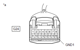
| (b) Disconnect the G24 drive mode select switch (electric parking brake switch assembly) connector. |
|
(c) Measure the resistance according to the value(s) in the table below.
Standard Resistance:
|
Tester Connection | Condition |
Specified Condition |
|---|---|---|
|
G24-16 (GND1) - Body ground |
Always | Below 1 Ω |
| NG | | REPAIR OR REPLACE HARNESS OR CONNECTOR |
|
| 4. |
INSPECT DRIVE MODE SELECT SWITCH (ELECTRIC PARKING BRAKE SWITCH ASSEMBLY) |
(a) Inspect drive mode select switch (electric parking brake switch assembly).
Click here
OK:
Drive mode select switch (Electric parking brake switch assembly) is normal.
|
Result | Proceed to |
|---|---|
|
CAN communication system DTCs are not output. |
A |
| CAN communication system DTCs are output. |
B |
| B |
| REPLACE DRIVE MODE SELECT SWITCH (ELECTRIC PARKING BRAKE SWITCH ASSEMBLY) |
|
| 5. |
CHECK HARNESS AND CONNECTOR (DRIVE MODE SELECT SWITCH (ELECTRIC PARKING BRAKE SWITCH ASSEMBLY) - ECM) |
(a) Connect the G24 drive mode select switch (electric parking brake switch assembly) connector.
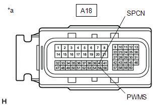
| (b) Disconnect the A18 ECM connectors. |
|
(c) Measure the resistance according to the value(s) in the table below.
Standard Resistance:
w/ Adaptive Variable Suspension System|
Tester Connection | Condition |
Specified Condition |
|---|---|---|
|
A18-55 (PWMS) - Body ground |
SPORT S/S+ mode switch being turned and held |
Below 1 Ω |
| A18-55 (PWMS) - Body ground |
SPORT S/S+ mode switch not turned |
10 kΩ or higher |
|
A18-40 (SPCN) - Body ground |
NORMAL/CUSTOM mode switch being pushed and held |
Below 1 Ω |
|
A18-40 (SPCN) - Body ground |
NORMAL/CUSTOM mode switch not pushed |
10 kΩ or higher |
|
Tester Connection | Condition |
Specified Condition |
|---|---|---|
|
A18-55 (PWMS) - Body ground |
SPORT mode switch being turned and held |
Below 1 Ω |
| A18-55 (PWMS) - Body ground |
SPORT mode switch not turned |
10 kΩ or higher |
|
A18-40 (SPCN) - Body ground |
NORMAL mode switch being pushed and held |
Below 1 Ω |
|
A18-40 (SPCN) - Body ground |
NORMAL mode switch not pushed |
10 kΩ or higher |
| OK | | REPLACE ECM |
| NG | | REPAIR OR REPLACE HARNESS OR CONNECTOR |
DTC CHECK / CLEAR
CHECK DTCs (USING TECHSTREAM)
(a) Turn the engine switch off.
(b) Connect the Techstream to the DLC3.
(c) Turn the engine switch on (IG).
(d) Turn the Techstream on.
(e) Enter the following menus: Chassis / EMPS / Trouble Codes.
Chassis > EMPS > Trouble Codes(f) Check the details of the DTCs.
Click here

CHECK DTCs (USING SST CHECK WIRE)
(a) Using SST, connect terminals 13 (TC) and 4 (CG) of the DLC3.
SST: 09843-18040
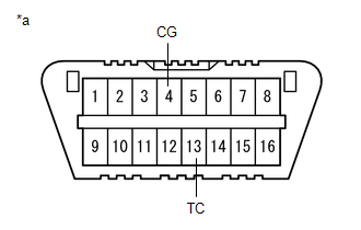
|
*a | DLC3 |
(b) Turn the engine switch on (IG).
(c) Read and write down any DTCs indicated by the blinking of the EPS warning light in the combination meter assembly. Refer to the illustration to the right for examples of the normal system code and DTCs 21 and 22.
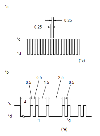
|
*a | Normal System Code |
|
*b | Codes 21 and 22 |
|
*c | ON |
|
*d | OFF |
|
*e | Seconds |
|
*f | Code 21 |
|
*g | Code 22 |
HINT:
|
Trouble Area |
Link |
|---|---|
|
EPS warning light circuit |
|
(d) Refer to Diagnostic Trouble Code Chart for DTC information.
Click here
(e) Check the details of the DTCs.
EPS DTC|
EPS Warning Light Display |
Tester Display |
|---|---|
|
11 | C1511 |
|
C1512 | |
| C1513 | |
|
C1514 | |
| C1517 | |
|
12 | C1528 |
|
13 | C1541 |
|
15 | C1515 |
|
16 | C1516 |
|
22 | C1552 |
|
23 | C1554 |
|
24 | C1521 |
|
C1522 | |
| C1523 | |
|
25 | C1531 |
|
C1532 | |
| C1533 | |
|
C1534 | |
| C1551 | |
|
C1555 | |
|
26 | C1581 |
|
C1582 | |
| 41 |
U0100 |
| 42 |
U0129 |
| 43 |
U0132 |
| 44 |
C1567 |
| 45 |
U023A |
| 47 |
U0126 |
CLEAR DTCs (USING TECHSTREAM)
(a) Turn the engine switch off.
(b) Connect the Techstream to the DLC3.
(c) Turn the engine switch on (IG).
(d) Turn the Techstream on.
(e) Enter the following menus: Chassis / EMPS / Trouble Codes.
Chassis > EMPS > Trouble Codes(f) Clear the DTCs.
Chassis > EMPS > Clear DTCs(g) Turn the engine switch off.
(h) Disconnect the Techstream from the DLC3.
CAUTION / NOTICE / HINT
NOTICE:
Click here 
PROCEDURE
|
1. | INSPECT COMBINATION METER ASSEMBLY |
(a) Perform the Active Test of the combination meter assembly using the Techstream.
Click here
|
Tester Display |
|---|
| EPS Warning |
(b) Check the combination meter assembly.
OK:
The EPS warning light turns on or off in accordance with the Techstream operation.
| OK |  | REPLACE RACK AND PINION POWER STEERING GEAR ASSEMBLY |
| NG | | GO TO METER / GAUGE SYSTEM |
FAIL-SAFE CHART
If a problem occurs in the power steering system, the power steering assist will be stopped or the amount of power assist will be decreased to protect the system.
Power Steering System|
Malfunction | Fail-safe Operation |
EPS warning light | Buzzer |
|---|---|---|---|
| Power steering assist stops or assist amount is limited |
Red or yellow | Sounds intermittently or once |
| Power steering assist is temporarily limited |
Yellow | Sounds once |
HINT:
FREEZE FRAME DATA
FREEZE FRAME DATA
NOTICE:
(a) Turn the engine switch off.
(b) Connect the Techstream to the DLC3.
(c) Turn the engine switch on (IG).
(d) Turn the Techstream on.
(e) Check the freeze frame data on the Techstream.
Chassis > EMPS|
Tester Display | Measurement Item |
Range | Normal Condition |
Diagnostic Note |
|---|---|---|---|---|
|
Meter Vehicle Velocity |
Vehicle speed from speedometer |
Min.: 0.0 km/h (0.0 MPH) Max.: 300.0 km/h (186.4 MPH) |
| - |
|
Wheel Speed Right | Rear right wheel speed |
Min.: 0 km/h (0 MPH) Max.: 255 km/h (158 MPH) |
| - |
|
Wheel Speed Left | Rear left wheel speed |
Min.: 0 km/h (0 MPH) Max.: 255 km/h (158 MPH) |
| - |
|
Engine Revolution | Engine speed |
Min.: 0 rpm Max.: 12800 rpm |
No significant fluctuation |
Engine running at a constant speed |
|
Motor Actual Current | Amount of current to motor |
Min.: -327.68 A Max.: 327.67 A |
Value changes in proportion to steering effort - The value increases when turning right and decreases when turning left |
Engine running and steering wheel being turned |
|
Command Value Current | Requested current to motor |
Min.: -327.68 A Max.: 327.67 A |
Value changes in proportion to steering effort - The value increases when turning right and decreases when turning left |
Engine running and steering wheel being turned |
|
Steering Angle Velocity |
Steering angle speed | Min.: -32768 deg/s Max.: 32767 deg/s | Value changes in proportion to steering speed - The value increases when turning left and decreases when turning right |
Engine running and steering wheel being turned |
|
Thermistor Temperature |
ECU substrate temperature |
Min.: -50.0°C (-58.0°F) Max.: 150.0°C (302.0°F) |
-50°C to 150°C (-58°F to 302°F) |
- |
| IG Power Supply |
IG power source voltage |
Min.: 0.0000 V Max.: 20.1531 V |
8 to 16 V | Engine switch on (IG) |
|
Steering Wheel Torque | Steering wheel torque |
Min.: -327.68 Nm Max.: 7.00 Nm |
Value changes in proportion to steering effort - The value increases when turning left and decreases when turning right |
Engine running and steering wheel being turned |
|
Motor Rotation Angle | Motor rotation angle |
Min.: 0.000 deg Max.: 1441.770 deg |
During steering operation, motor rotation angle value changes from 0 to 360° |
Engine running and steering wheel being turned |
|
Command Val Current 2 | Requested current to motor |
Min.: -327.68 A Max.: 327.67 A |
Value changes in proportion to steering effort |
Engine running and steering wheel being turned |
|
Motor Voltage | Motor power supply voltage |
Min.: 0.000 V Max.: 98.000 V |
| - |
|
TRQ1 Zero Point Value | Zero point value of torque sensor 1 |
Min.: 0.0000 V Max.: 4.9725 V |
2.3 to 2.7 V | Engine running and steering wheel not being turned (without load) |
|
TRQ2 Zero Point Value | Zero point value of torque sensor 2 |
Min.: 0.0000 V Max.: 4.9725 V |
2.3 to 2.7 V | Engine running and steering wheel not being turned (without load) |
|
PS Assist Signal | Status of the record of power steering assist signal |
OFF or ON | OFF: Engine switch on (IG) ON: Engine running | - |
|
Motor Actual Current 2 |
Amount of current to motor |
Min.: -327.68 A Max.: 327.67 A |
Value changes in proportion to steering effort |
Engine running and steering wheel being turned |
|
Rotation Angle Sens Avg(SIN) |
Rotation angle sensor average (SIN) |
Min.: 0.0000 V Max.: 4.9725 V |
- | - |
|
Rotation Angle Sens Avg(COS) |
Rotation angle sensor average (COS) |
Min.: 0.0000 V Max.: 4.9725 V |
- | - |
|
Steering Angle | Steering angle |
Min.: -3072.0 deg Max.: 3070.5 deg |
- | - |
|
Torque Sensor 1 Output |
Torque sensor 1 output value |
Min.: 0.0000 V Max.: 4.9725 V |
- | - |
|
Torque Sensor 2 Output |
Torque sensor 2 output value |
Min.: 0.0000 V Max.: 4.9725 V |
- | - |
|
Torque Sensor 1 Power Supply |
Torque sensor 1 power supply voltage |
Min.: 0.0000 V Max.: 4.9725 V |
- | - |
|
Torque Sensor 2 Power Supply |
Torque sensor 2 power supply voltage |
Min.: 0.0000 V Max.: 4.9725 V |
- | - |
|
Rotation Angle Sensor Output 1 |
Rotation angle sensor Vx1 output voltage |
Min.: 0.0000 V Max.: 4.9725 V |
- | - |
|
Rotation Angle Sensor Output 2 |
Rotation angle sensor Vx2 output voltage |
Min.: 0.0000 V Max.: 4.9725 V |
- | - |
|
Rotation Angle Sensor Output 3 |
Rotation angle sensor Vy1 output voltage |
Min.: 0.0000 V Max.: 4.9725 V |
- | - |
|
Rotation Angle Sensor Output 4 |
Rotation angle sensor Vy2 output voltage |
Min.: 0.0000 V Max.: 4.9725 V |
- | - |
|
Motor 1 Terminal Current (U) |
Motor 1 terminal current (U phase) |
Min.: -327.68 A Max.: 327.67 A |
Value changes in proportion to steering effort |
Engine running and steering wheel being turned |
|
Motor 1 Terminal Current (V) |
Motor 1 terminal current (V phase) |
Min.: -327.68 A Max.: 327.67 A |
Value changes in proportion to steering effort |
Engine running and steering wheel being turned |
|
Motor 1 Terminal Current (W) |
Motor 1 terminal current (W phase) |
Min.: -327.68 A Max.: 327.67 A |
Value changes in proportion to steering effort |
Engine running and steering wheel being turned |
|
Motor 2 Terminal Current (U) |
Motor 2 terminal current (U phase) |
Min.: -327.68 A Max.: 327.67 A |
Value changes in proportion to steering effort |
Engine running and steering wheel being turned |
|
Motor 2 Terminal Current (V) |
Motor 2 terminal current (V phase) |
Min.: -327.68 A Max.: 327.67 A |
Value changes in proportion to steering effort |
Engine running and steering wheel being turned |
|
Motor 2 Terminal Current (W) |
Motor 2 terminal current (W phase) |
Min.: -327.68 A Max.: 327.67 A |
Value changes in proportion to steering effort |
Engine running and steering wheel being turned |
|
Motor 1 U Phase Duty | Motor 1 U phase duty |
Min.: 0.00% Max.: 100.00% |
- | - |
|
Motor 1 V Phase Duty | Motor 1 V phase duty |
Min.: 0.00% Max.: 100.00% |
- | - |
|
Motor 1 W Phase Duty | Motor 1 W phase duty |
Min.: 0.00% Max.: 100.00% |
- | - |
|
Motor 2 U Phase Duty | Motor 2 U phase duty |
Min.: 0.00% Max.: 100.00% |
- | - |
|
Motor 2 V Phase Duty | Motor 2 V phase duty |
Min.: 0.00% Max.: 100.00% |
- | - |
|
Motor 2 W Phase Duty | Motor 2 W phase duty |
Min.: 0.00% Max.: 100.00% |
- | - |
|
Motor 1 Terminal Volt (U) |
Motor 1 terminal voltage (U phase) |
Min.: 0.000 V Max.: 98.000 V |
Value changes within 4 to 35 V range |
Engine running and steering wheel being turned |
|
Motor 1 Terminal Volt (V) |
Motor 1 terminal voltage (V phase) |
Min.: 0.000 V Max.: 98.000 V |
Value changes within 4 to 35 V range |
Engine running and steering wheel being turned |
|
Motor 1 Terminal Volt (W) |
Motor 1 terminal voltage (W phase) |
Min.: 0.000 V Max.: 98.000 V |
Value changes within 4 to 35 V range |
Engine running and steering wheel being turned |
|
Motor 2 Terminal Volt (U) |
Motor 2 terminal voltage (U phase) |
Min.: 0.000 V Max.: 98.000 V |
Value changes within 4 to 35 V range |
Engine running and steering wheel being turned |
|
Motor 2 Terminal Volt (V) |
Motor 2 terminal voltage (V phase) |
Min.: 0.000 V Max.: 98.000 V |
Value changes within 4 to 35 V range |
Engine running and steering wheel being turned |
|
Motor 2 Terminal Volt (W) |
Motor 2 terminal voltage (W phase) |
Min.: 0.000 V Max.: 98.000 V |
Value changes within 4 to 35 V range |
Engine running and steering wheel being turned |
|
Motor 1 PIG Power Supply |
Power supply voltage to active motor 1 |
Min.: 0.0000 V Max.: 20.1531 V |
9 to 16 V | Engine running and steering wheel being turned |
|
Motor 2 PIG Power Supply |
Power supply voltage to active motor 2 |
Min.: 0.0000 V Max.: 20.1531 V |
9 to 16 V | Engine running and steering wheel being turned |
CAUTION / NOTICE / HINT
HINT:
PROCEDURE
|
1. | VEHICLE BROUGHT TO WORKSHOP |
|
| 2. |
INSPECT BATTERY |
(a) Turn the engine switch off.
(b) Measure the voltage of the battery.
Standard Voltage:
11 to 14 V
HINT:
If the voltage is below 11 V, recharge or replace the battery before proceeding to the next step.
|
| 3. |
CHECK DTC AND FREEZE FRAME DATA* |
HINT:
Refer to DTC Check / Clear.
Chassis > EMPS > Trouble Codes
|
| 4. |
PROBLEM SYMPTOM CONFIRMATION |
|
Result | Proceed to |
|---|---|
|
Symptom does not occur. |
A |
| Symptom occurs. |
B |
| B |
 | GO TO STEP 6 |
|
| 5. |
SYMPTOM SIMULATION |
|
| 6. |
CHECK CAN COMMUNICATION SYSTEM* |
(a) Check for DTCs.
Click here 
|
Result | Proceed to |
|---|---|
|
CAN communication system DTCs are not output. |
A |
| CAN communication system DTCs are output. |
B |
HINT:
| B | | PROCEED TO CAN COMMUNICATION SYSTEM |
|
| 7. |
CHECK FOR DTC* |
(a) Check for DTCs.
Chassis > EMPS > Trouble CodesHINT:
Refer to Diagnostic Trouble Code Chart when any DTCs are output.
Click here
|
Result | Proceed to |
|---|---|
|
DTCs are not output. |
A |
| DTCs are output. |
B |
| B |
| GO TO STEP 10 |
|
| 8. |
PROBLEM SYMPTOMS TABLE |
(a) Refer to Problem Symptoms Table.
Click here
|
Result | Proceed to |
|---|---|
|
Fault is not listed in Problem Symptoms Table. |
A |
| Fault is listed in Problem Symptoms Table. |
B |
| B |
| GO TO STEP 10 |
|
| 9. |
OVERALL ANALYSIS AND TROUBLESHOOTING* |
(a) Refer to Terminals of ECU.
Click here
(b) Refer to Data List / Active Test.
Click here
|
| 10. |
REPAIR OR REPLACE |
|
| 11. |
CONFIRMATION TEST |
| NEXT | | END |
ON-VEHICLE INSPECTION
PROCEDURE
1. CHECK STEERING EFFORT (TORQUE)
NOTICE:
These service operations may affect the SRS airbags. Be sure to read the precautionary notices concerning the SRS airbag system before servicing.
Click here

(a) Stop the vehicle on a level, paved surface and align the wheels straight ahead.
(b) Remove the horn button assembly.
Click here
(c) Connect the cable to the negative (-) battery terminal.
(d) Using a torque wrench, check that the steering wheel set bolt is properly tightened.
Torque:
62 N·m {632 kgf·cm, 46 ft·lbf}
(e) Start the engine so that the power steering is ready to operate.
(f) Turn the steering wheel 90 degrees to the right and check steering effort (torque) with the steering wheel turned. Check in the opposite direction using the same method.
Standard Steering Effort (Reference):
5.5 N*m (56 kgf*cm, 49 in.*lbf) or less
(g) Align the front wheels facing straight ahead.
(h) Turn the engine switch off.
(i) Disconnect the cable from the negative (-) battery terminal.
NOTICE:
When disconnecting the cable, some systems need to be initialized after the cable is reconnected.
Click here
(j) Install the horn button assembly.
Click here
PARTS LOCATION
ILLUSTRATION
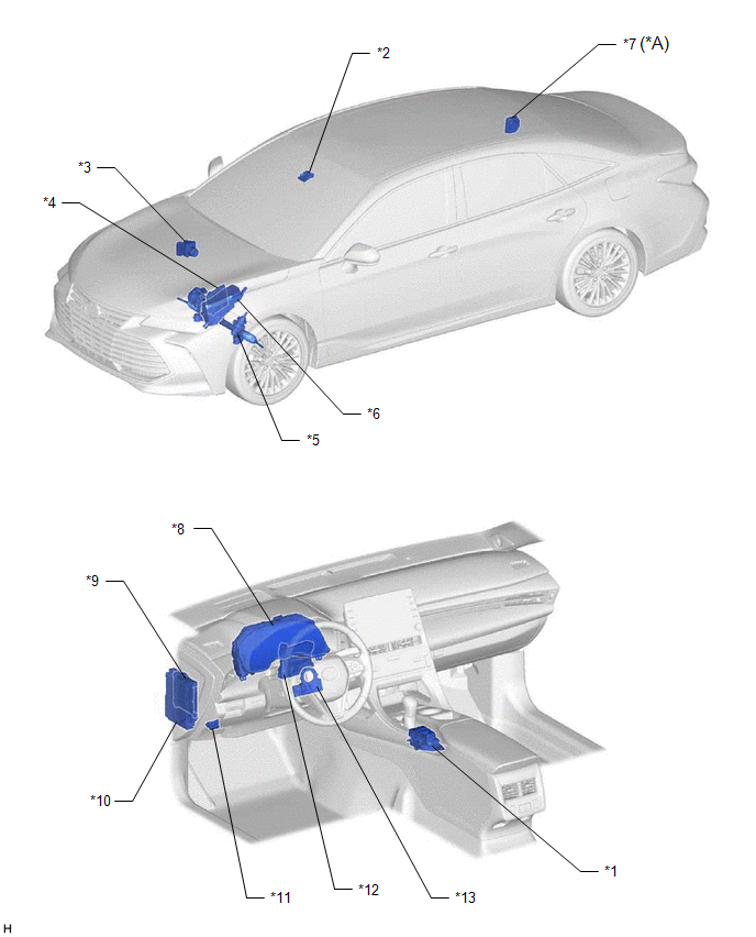
|
*A | w/ Adaptive Variable Suspension System |
- | - |
|
*1 | DRIVE MODE SELECT SWITCH (ELECTRIC PARKING BRAKE SWITCH ASSEMBLY) |
*2 | FORWARD RECOGNITION CAMERA |
|
*3 | BRAKE ACTUATOR ASSEMBLY - SKID CONTROL ECU | *4 |
ECM |
| *5 |
RACK AND PINION POWER STEERING GEAR ASSEMBLY - POWER STEERING ECU -POWER STEERING MOTOR -TORQUE SENSOR |
*6 | NO. 1 ENGINE ROOM RELAY BLOCK AND NO. 1 JUNCTION BLOCK - EPS FUSE |
|
*7 | AVS ECU (ABSORBER CONTROL ECU) |
*8 | COMBINATION METER ASSEMBLY |
|
*9 | MAIN BODY ECU (MULTIPLEX NETWORK BODY ECU) |
*10 | INSTRUMENT PANEL JUNCTION BLOCK ASSEMBLY - IG1-NO. 1 RELAY - EPS-IG1 FUSE |
|
*11 | DLC3 |
*12 | AIR CONDITIONING AMPLIFIER ASSEMBLY |
|
*13 | STEERING SENSOR |
- | - |
PRECAUTION
PRECAUTION FOR DISCONNECTING CABLE FROM NEGATIVE BATTERY TERMINAL
NOTICE:
When disconnecting the cable from the negative (-) battery terminal, initialize the following system(s) after the cable is reconnected.
|
System | Procedure |
|---|---|
|
Lane Departure Alert System (w/ Steering Control) |
|
|
Pre-collision System | |
|
Intelligent Clearance Sonar System | |
|
Lighting System (for Gasoline Model with Cornering Light) | |
|
Parking Assist Monitor System | |
|
Panoramic View Monitor System |
HANDLING PRECAUTIONS FOR SRS AIRBAG SYSTEM
(a) This vehicle is equipped with a Supplemental Restraint System (SRS). Failure to carry out service operations in the correct sequence could cause the SRS to unexpectedly deploy during servicing. This may cause a serious accident.
Before servicing (including inspection, replacement, removal and installation of parts), be sure to read the precautionary notices for the Supplemental Restraint System.
Click here

PRECAUTIONS FOR REMOVAL, INSTALLATION AND REPLACEMENT OF ELECTRONIC POWER STEERING COMPONENTS
(a) Be sure to align the front wheels straight ahead when removing and installing the rack and pinion power steering gear assembly.
(b) When disconnecting the steering intermediate shaft assembly, be sure to place matchmarks before starting the operation.
(c) After replacing the rack and pinion power steering gear assembly, calibrate the torque sensor zero point.
Click here
HANDLING PRECAUTION
(a) When handling electronic parts:
(1) Do not subject any parts such as ECUs and relays to any impact. Replace them with new ones if dropped or subjected to a strong impact.
(2) Do not expose any electronic parts to high temperatures or humidity.
(3) In order to prevent deformation or malfunctions due to static electricity, do not touch the connector terminals.
(b) When handling the rack and pinion power steering gear assembly:
(1) When replacing the power steering ECU (rack and pinion power steering gear assembly), make sure to replace each rack and pinion power steering gear assembly with a new one.
NOTICE:
Do not use a rack and pinion power steering gear assembly intended from another vehicle (demo models, etc.).
(2) Do not subject the rack and pinion power steering gear assembly to any strong impact (particularly the motor and torque sensor). Replace these parts with new ones if dropped or subjected to any severe impact.
(3) Do not pull the harness when carrying the rack and pinion power steering gear assembly.
(4) When the rack and pinion power steering gear assembly has been replaced, perform assist map writing and torque sensor zero point calibration.
Click here
PRECAUTIONS FOR CAN COMMUNICATION
(a) CAN communication lines are used to receive information from the skid control ECU (brake actuator assembly) and ECM and to transmit warnings to the combination meter assembly. When problems are detected in the CAN communication lines, CAN communication DTCs are stored.
(b) If any CAN communication system DTCs are output, perform troubleshooting for the CAN communication system first.
(c) The wiring used for each communication line is a twisted pair of wires that have an equal length. Do not temporarily repair a CAN communication line with a bypass wire or equivalent.
PROBLEM SYMPTOMS TABLE
HINT:
|
Symptom | Suspected Area |
Link |
|---|---|---|
|
Heavy steering | Check assist limit record |
|
|
Front tires (improperly inflated, unevenly worn) |
| |
|
Front wheel alignment (incorrect) |
| |
|
Front suspension (Lower ball joint) |
| |
|
Rack and pinion power steering gear assembly |
| |
|
Steering effort differs between right and left or is uneven |
Rotation angle sensor initialization and torque sensor zero point calibration incomplete |
|
|
Front tires (improperly inflated, unevenly worn) |
| |
|
Front wheel alignment (incorrect) |
| |
|
Front suspension (Lower ball joint) |
| |
|
Rack and pinion power steering gear assembly |
| |
|
Steering column assembly (for Manual Tilt and Manual Telescopic Steering Column) |
| |
|
Steering column assembly (for Power Tilt and Power Telescopic Steering Column) |
| |
|
While driving, steering effort does not change in accordance with vehicle speed, or steering wheel does not return to its centered position easily |
Skid control ECU (Brake actuator assembly) |
|
|
Speed sensor |
| |
|
Rack and pinion power steering gear assembly |
| |
|
CAN communication system |
| |
|
Friction sounds occur when turning steering wheel during low speed driving |
Rack and pinion power steering gear assembly |
|
|
Steering column assembly (for Manual Tilt and Manual Telescopic Steering Column) |
| |
|
Steering column assembly (for Power Tilt and Power Telescopic Steering Column) |
| |
|
Spiral with cable sensor sub-assembly |
| |
|
Steering column cover contacting steering wheel assembly (for Manual Tilt and Manual Telescopic Steering Column) |
| |
|
Steering column cover contacting steering wheel assembly (for Power Tilt and Power Telescopic Steering Column) |
| |
|
High-pitched sound (squeaking) occurs when turning steering wheel slowly with vehicle stopped |
Rack and pinion power steering gear assembly |
|
|
Steering wheel installation (incorrect) |
| |
|
Steering wheel vibrates and noise occurs when turning steering wheel from lock to lock |
Rack and pinion power steering gear assembly |
|
|
Steering column assembly (for Manual Tilt and Manual Telescopic Steering Column) |
| |
|
Steering column assembly (for Power Tilt and Power Telescopic Steering Column) |
| |
|
Steering wheel installation (incorrect) |
| |
|
Drive mode does not change |
Drive more select switch circuit |
|
|
EPS warning light remains on | EPS warning light circuit |
|
SYSTEM DESCRIPTION
DESCRIPTION
(a) The power steering ECU (rack and pinion power steering gear assembly) generates the necessary steering assist torque by calculating the steering assist force and controlling the motor current, based on the steering torque information from the torque sensor (rack and pinion power steering gear assembly), vehicle speed information from the skid control ECU (brake actuator assembly), and information from the ECUs.
(b) When there is a drop in the power source voltage, the rear window defogger, windshield deicer, outer mirror heater, PTC heater and seat heater operations are limited as part of power steering system load control.
(c) When there is a drop in the power source that may require an increase in steering force, the system illuminates the power steering warning light in order to warn the driver.
Function of Components:|
Component | Function | |
|---|---|---|
| *: w/ Adaptive Variable Suspension System | ||
| Rack and Pinion Power Steering Gear Assembly HINT: The components listed on the right are built-in |
Power Steering ECU |
|
| Power Steering Motor |
| |
| Torque Sensor |
Detects the steering torque. | |
|
Reduction Mechanism | Decelerates the motor rotation torque and transmits it to the rack shaft. | |
|
Steering Sensor | Detects the steering angle and steering direction. | |
|
Skid Control ECU (Brake Actuator Assembly) |
Sends the vehicle speed signal and steering coordinated control amount signal to the rack and pinion power steering gear assembly. | |
|
ECM |
| |
| Air Conditioning Amplifier Assembly |
Receives a signal from the power steering ECU (rack and pinion power steering gear assembly) to limit electrical usage. | |
|
AVS ECU (Absorber Control ECU)* |
Transmits the drive mode select signal to the power steering ECU assembly. | |
|
Combination Meter Assembly |
EPS Warning Light | Illuminates to alert the driver when the power steering ECU (rack and pinion power steering gear assembly) detects a malfunction in the power steering system. |
| Multi-information Display |
Displays a warning message to inform the driver of a malfunction in the system. | |
|
Master Warning Light | Illuminates when a warning message is displayed on the multi-information display. | |
|
Multi Buzzer | Sounds to warn the driver of a malfunction in the system. | |
|
Forward Recognition Camera |
Requests steering assist torque when the lane departure alert system judges that the vehicle is departing from its lane. | |
|
Drive Mode Select Switch (Electric Parking Brake Switch Assembly) |
Switches the driving mode. | |
SYSTEM DIAGRAM
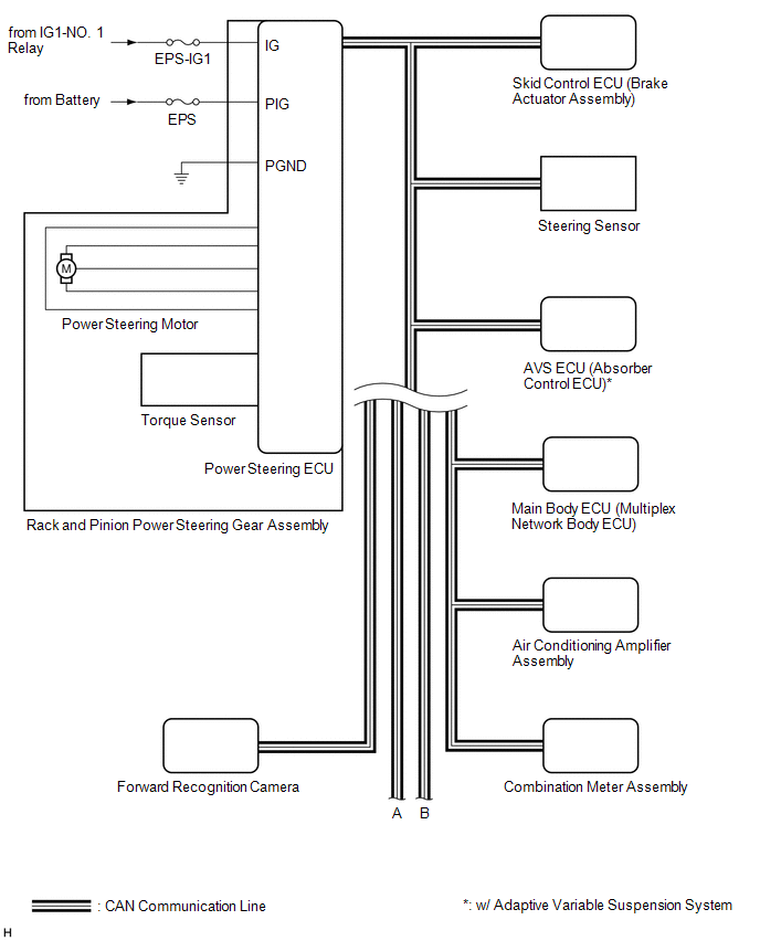
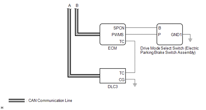
TERMINALS OF ECU
TERMINALS OF ECU

|
*a | Component without harness connected (Rack and Pinion Power Steering Gear Assembly) |
- | - |
HINT:
Click here 
|
Terminal No. (Symbol) | Terminal Description |
|---|---|
|
C67-4 (IG) | IG power source |
|
C67-7 (PGND) | power ground |
|
C67-8 (PIG) | power source |
|
C67-10 (CANH) | CAN communication line |
|
C67-11 (CANL) | CAN communication line |
CHECK WIRE HARNESS SIDE CONNECTOR

|
*a | Front view of wire harness connector (to Rack and Pinion Power Steering Gear Assembly) |
- | - |
(a) Disconnect the C67 rack and pinion power steering gear assembly.
(b) Measure the voltage and resistance according to the value(s) in the table below.
|
Terminal No. (Symbol) | Wiring Color |
Terminal Description | Condition |
Specified Condition |
|---|---|---|---|---|
|
C67-4 (IG) - Body ground |
W - Body ground | IG power source |
Engine switch on (IG) |
8 to 16 V |
| C67-7 (PGND) - Body ground |
B - Body ground | power ground |
Always | Below 1 Ω |
|
C67-8 (PIG) - Body ground |
W - Body ground | power source |
Always | 9 to 16 V |
DESCRIPTION
The power steering ECU (rack and pinion power steering gear assembly) receives signals from the ECM, steering sensor, skid control ECU (brake actuator assembly), AVS ECU (absorber control ECU) and forward recognition camera via CAN communication.
|
DTC No. | Detection Item |
DTC Detection Condition | Trouble Area |
Warning Indicate | Return-to-normal Condition |
Note |
|---|---|---|---|---|---|---|
| U0100 |
Lost Communication with ECM / PCM "A" |
Lost communication with ECM |
| EPS warning light: When an error occurs during steering assist, the warning light does not illuminate. For errors that occur before assist (at the time of the decision to start assist), the warning light illuminates. |
The ECU judges the system has returned to normal |
- |
| U0126 |
Lost Communication With Steering Angle Sensor Module |
Lost communication with steering angle sensor |
| EPS warning light: Comes on |
The ECU judges the system has returned to normal |
- |
| U0129 |
Lost Communication with Brake System Control Module |
Lost communication with skid control ECU (Brake actuator assembly) |
| EPS warning light: Comes on |
The ECU judges the system has returned to normal |
- |
| U0132 |
Lost Communication with Ride Level Control Module |
Lost communication with AVS ECU (absorber control ECU) |
| EPS warning light: Does not come on |
The ECU judges the system has returned to normal |
w/ Adaptive Variable Suspension System |
|
U023A | Lost Communication with Front Camera Module |
Lost communication with forward recognition camera |
| EPS warning light: Does not come on |
The ECU judges the system has returned to normal |
- |
PROCEDURE
| 1. |
GO TO CAN COMMUNICATION SYSTEM |
(a) Go to CAN communication system.
Click here 
| NEXT |  | END |
Toyota Avalon (XX50) 2019-2022 Service & Repair Manual > 2gr-fks Fuel: Fuel Sender Gauge Assembly
Components COMPONENTS ILLUSTRATION *A Type A *B Type B *1 FUEL SENDER GAUGE ASSEMBLY *2 FUEL SUCTION TUBE WITH PUMP AND GAUGE ASSEMBLY Inspection INSPECTION PROCEDURE 1. INSPECT FUEL SENDER GAUGE ASSEMBLY CAUTION: Perform the inspection in a well-ventilated area. Do not perform the inspection near a ...