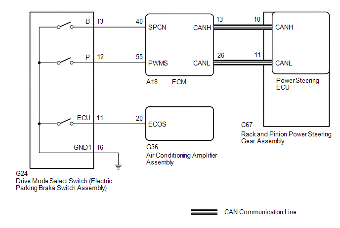
DESCRIPTION The
characteristics of the electronic throttle and EPS operation change
according to operation of the drive mode select switch (electric parking
brake switch assembly). WIRING DIAGRAM
 PROCEDURE
| 1. |
CHECK THE PROBLEM SYMPTOMS | (a) Check each symptom by checking the suspected areas in the table below.
|
Result | Proceed to | |
SPORT mode or NORMAL mode is abnormal. |
A | | ECO mode is abnormal. |
B |
| B |
 | GO TO AIR CONDITIONING SYSTEM |
|
A |
 | |
| 2. |
CHECK CAN COMMUNICATION SYSTEM | (a) Check for DTCs.
Click here 
|
Result | Proceed to | |
CAN communication system DTCs are not output. |
A | | CAN communication system DTCs are output. |
B |
| B |
| GO TO CAN COMMUNICATION SYSTEM |
|
A | |
| |
| 3. |
CHECK HARNESS AND CONNECTOR (DRIVE MODE SELECT SWITCH (ELECTRIC PARKING BRAKE SWITCH ASSEMBLY) - BODY GROUND) |
(a) Turn the engine switch off.
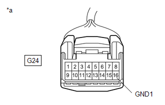
| (b) Disconnect the G24 drive mode select switch (electric parking brake switch assembly) connector. |
 |
|
*a | Front view of wire harness connector
(to Drive mode select switch (Electric parking brake switch assembly)) | | |
(c) Measure the resistance according to the value(s) in the table below.
Standard Resistance: |
Tester Connection | Condition |
Specified Condition | |
G24-16 (GND1) - Body ground |
Always | Below 1 Ω |
| NG |
| REPAIR OR REPLACE HARNESS OR CONNECTOR |
|
OK | |
| |
| 4. |
INSPECT DRIVE MODE SELECT SWITCH (ELECTRIC PARKING BRAKE SWITCH ASSEMBLY) |
(a) Inspect drive mode select switch (electric parking brake switch assembly).
Click here OK: Drive mode select switch (Electric parking brake switch assembly) is normal.
|
Result | Proceed to | |
CAN communication system DTCs are not output. |
A | | CAN communication system DTCs are output. |
B |
| B |
| REPLACE DRIVE MODE SELECT SWITCH (ELECTRIC PARKING BRAKE SWITCH ASSEMBLY) |
|
A | |
| |
| 5. |
CHECK HARNESS AND CONNECTOR (DRIVE MODE SELECT SWITCH (ELECTRIC PARKING BRAKE SWITCH ASSEMBLY) - ECM) |
(a) Connect the G24 drive mode select switch (electric parking brake switch assembly) connector.
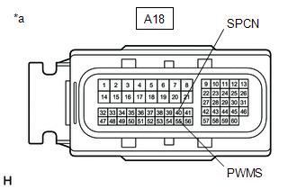
| (b) Disconnect the A18 ECM connectors. |
 |
|
*a | Front view of wire harness connector
(to ECM) | | |
(c) Measure the resistance according to the value(s) in the table below.
Standard Resistance: w/ Adaptive Variable Suspension System |
Tester Connection | Condition |
Specified Condition | |
A18-55 (PWMS) - Body ground |
SPORT S/S+ mode switch being turned and held |
Below 1 Ω | | A18-55 (PWMS) - Body ground |
SPORT S/S+ mode switch not turned |
10 kΩ or higher | |
A18-40 (SPCN) - Body ground |
NORMAL/CUSTOM mode switch being pushed and held |
Below 1 Ω | |
A18-40 (SPCN) - Body ground |
NORMAL/CUSTOM mode switch not pushed |
10 kΩ or higher | w/o Adaptive Variable Suspension System |
Tester Connection | Condition |
Specified Condition | |
A18-55 (PWMS) - Body ground |
SPORT mode switch being turned and held |
Below 1 Ω | | A18-55 (PWMS) - Body ground |
SPORT mode switch not turned |
10 kΩ or higher | |
A18-40 (SPCN) - Body ground |
NORMAL mode switch being pushed and held |
Below 1 Ω | |
A18-40 (SPCN) - Body ground |
NORMAL mode switch not pushed |
10 kΩ or higher |
| OK |
| REPLACE ECM |
| NG |
| REPAIR OR REPLACE HARNESS OR CONNECTOR | | 

