REMOVAL CAUTION / NOTICE / HINT
The
necessary procedures (adjustment, calibration, initialization or
registration) that must be performed after parts are removed and
installed, or replaced during steering column assembly
removal/installation are shown below. Necessary Procedures After Parts Removed/Installed/Replaced (for Gasoline Model) |
Replaced Part or Performed Procedure |
Necessary Procedure | Effect/Inoperative Function when Necessary Procedure not Performed |
Link | |
*: When performing learning using the Techstream.
Click here  | |
Removal/installation of the turn signal switch assembly with spiral cable sub-assembly |
Steering angle zero point learning (Initialize intelligent clearance sonar system) |
- Intelligent Clearance Sonar System
- Intuitive Parking Assist System
|
|
- Steering angle zero point learning (Initialize parking assist monitor system)
- Steering angle setting
| Parking Assist Monitor System |
for Initialization
for Calibration | |
Steering angle zero point learning (Initialize panoramic view monitor system) |
Panoramic View Monitor System |
for Initialization
for Calibration | |
Steering lock ECU (steering lock actuator or upper bracket assembly) |
Code registration (Smart Key System (for Start Function)) |
- Wireless Door Lock Control System
- Smart Key System (for Entry Function)
- Smart Key System (for Start Function)
- Steering Lock Function
|
| |
Disconnect cable from negative auxiliary battery terminal |
Perform steering sensor zero point calibration |
Lane Departure Alert System (w/ Steering Control) |
| |
Pre-collision System | |
Intelligent Clearance Sonar System* | |
Lighting System (for Gasoline Model with Cornering Light) | |
Memorize steering angle neutral point |
Parking Assist Monitor System |
| |
Panoramic View Monitor System |
| Necessary Procedures After Parts Removed/Installed/Replaced (for HV Model) |
Replaced Part or Performed Procedure |
Necessary Procedure | Effect/Inoperative Function when Necessary Procedure not Performed |
Link | |
*: When performing learning using the Techstream.
Click here | |
Removal/installation of the turn signal switch assembly with spiral cable sub-assembly |
Steering angle zero point learning (Initialize intelligent clearance sonar system) |
- Intelligent Clearance Sonar System
- Intuitive Parking Assist System
|
|
- Steering angle zero point learning (Initialize parking assist monitor system)
- Steering angle setting
| Parking Assist Monitor System |
for Initialization
for Calibration | |
Steering angle zero point learning (Initialize panoramic view monitor system) |
Panoramic View Monitor System |
for Initialization
for Calibration | |
Steering lock ECU (steering lock actuator or upper bracket assembly) |
Code registration (Smart key System (for Start Function)) |
- Wireless Door Lock Control System
- Smart Key System (for Entry Function)
- Smart Key System (for Start Function)
- Steering Lock Function
|
| |
Disconnect cable from negative auxiliary battery terminal |
Perform steering sensor zero point calibration |
Lane Departure Alert System (w/ Steering Control) |
| |
Pre-collision System | |
Intelligent Clearance Sonar System* | |
Lighting System (for HV Model with Cornering Light) | |
Memorize steering angle neutral point |
Parking Assist Monitor System |
| |
Panoramic View Monitor System |
| PROCEDURE
1. PRECAUTION Click here 2. ALIGN FRONT WHEELS FACING STRAIGHT AHEAD
3. REMOVE HORN BUTTON ASSEMBLY Click here
4. REMOVE STEERING WHEEL ASSEMBLY
Click here 5. REMOVE LOWER STEERING COLUMN COVER
NOTICE: Removing the lower steering column cover in the incorrect order will cause the parts to break.
(a) Release the tilt and telescopic lever and fully extend and lower the steering column assembly.
(b) Lock the tilt and telescopic lever.
 |
Push Area |
 |
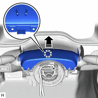
Push in this direction | (d)
While pressing the push area shown in the illustration to disengage the
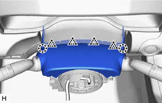
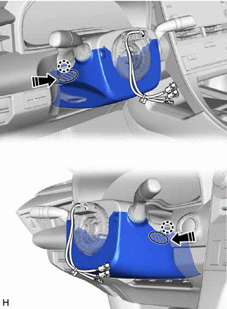
2 claws, slightly lower the lower steering column cover. 6. REMOVE UPPER STEERING COLUMN COVER
(a) Disengage the claw and separate the upper steering column cover.
|
|
Separate in this direction |
| (b) Disengage the 2 claws and 4 clips to remove the upper steering column cover. |
|
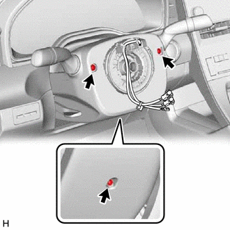
7. REMOVE TURN SIGNAL SWITCH ASSEMBLY WITH SPIRAL CABLE SUB-ASSEMBLY
NOTICE:
- Do not remove/install the spiral cable with sensor sub-assembly with the
auxiliary battery connected and the engine switch (for Gasoline Model)
or power switch (for HV Model) on (IG).
- Do not rotate the spiral cable with sensor sub-assembly without the
steering wheel assembly installed, with the auxiliary battery connected
and the engine switch (for Gasoline Model) or power switch (for HV
Model) on (IG).
- Ensure that the steering wheel assembly is installed and aligned straight when inspecting the steering sensor.
(a) Disconnect each connector from the turn signal switch assembly with spiral cable sub-assembly.
| (b) Using pliers, expand the clamp. | |
(c)
While holding the clamp expanded, raise the claw using a screwdriver to
disengage it, and then remove the turn signal switch assembly with
spiral cable sub-assembly from the steering column assembly. 8. REMOVE LOWER NO. 1 INSTRUMENT PANEL AIRBAG ASSEMBLY
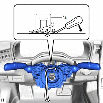
Click here 9. REMOVE NO. 1 AIR DUCT
(a) Remove the 2 bolts. 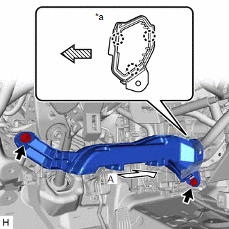
|
*a | View A |
 |
Front | (b) Disengage the 3 claws to remove the No. 1 air duct.
NOTICE: Be careful not to deform or damage the lower heater case of the air conditioner unit assembly when removing the No. 1 air duct.
10. REMOVE FRONT WHEEL LH Click here
11. SEPARATE STEERING INTERMEDIATE SHAFT ASSEMBLY (for Gasoline Model)
Click here 12. SEPARATE STEERING INTERMEDIATE SHAFT ASSEMBLY (for HV Model)
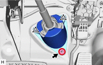
Click here 13. REMOVE STEERING COLUMN HOLE COVER
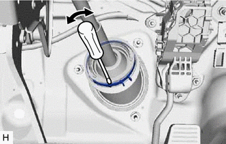
(a) Turn back the floor carpet.
(c) Disengage the 2 clips to remove the steering column hole cover. 14. REMOVE STEERING INTERMEDIATE SHAFT ASSEMBLY
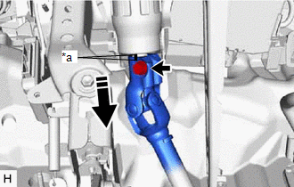
| (a) Using a screwdriver, loosen the clamp as shown in the illustration. |
|
(b) Remove the bolt and slide the steering intermediate shaft assembly.
NOTICE: Do not remove the steering intermediate shaft assembly from the steering column assembly.
|
*a | Matchmark | |
|
Slide in this direction | (c) Put matchmarks on the steering intermediate shaft assembly and steering column assembly.
(d) Remove the steering intermediate shaft assembly from the steering column assembly.
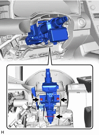
15. REMOVE STEERING COLUMN ASSEMBLY (a) Disconnect each connector and disengage each wire harness clamp from the steering column assembly.
| (b) Remove the bolt, 2 nuts and steering column assembly. |
| |