COMPONENTS
ILLUSTRATION
|
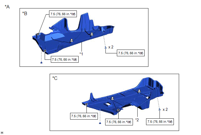
*A | for Gasoline Model |
*B | for RH Side |
|
*C | for LH Side |
- | - |
|
*1 | NO. 1 FLOOR UNDER COVER |
*2 | NO. 2 FLOOR UNDER COVER |
 |
N*m (kgf*cm, ft.*lbf): Specified torque |
- | - |
ILLUSTRATION
|
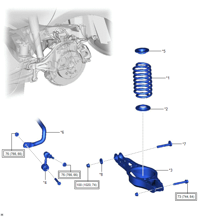
*1 | REAR COIL SPRING |
*2 | REAR LOWER COIL SPRING INSULATOR |
|
*3 | REAR NO. 2 SUSPENSION ARM ASSEMBLY |
*4 | REAR STABILIZER LINK ASSEMBLY |
|
*5 | REAR UPPER COIL SPRING INSULATOR |
*6 | REAR STABILIZER BAR |
|
*7 | REAR SUSPENSION TOE ADJUST CAM SUB-ASSEMBLY |
*8 | NO. 2 CAMBER ADJUST CAM |
 |
Tightening torque for "Major areas involving basic vehicle performance such as moving/turning/stopping": N*m (kgf*cm, ft.*lbf) |
- | - |
INSTALLATION
CAUTION / NOTICE / HINT
HINT:
PROCEDURE
1. INSTALL REAR UPPER COIL SPRING INSULATOR
(a) Install the rear upper coil spring insulator to the vehicle.
2. INSTALL REAR LOWER COIL SPRING INSULATOR
(a) Install the rear lower coil spring insulator to the rear No. 2 suspension arm assembly.
3. INSTALL REAR COIL SPRING
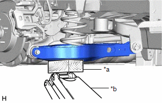
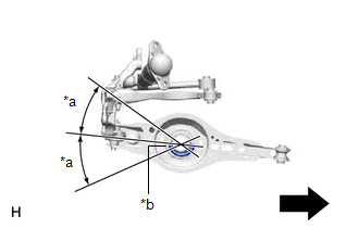
(a) Set the rear coil spring to the rear No. 2 suspension arm assembly.
NOTICE:
|
*a | 30° or less |
|
*b | Lower End of Rear Coil Spring |
 |
Inner Side of the Vehicle |
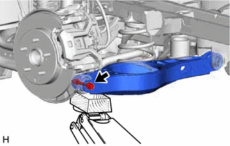
(b) Using a jack and wooden block, slowly jack up the rear No. 2 suspension arm assembly and then install the rear No. 2 suspension arm assembly to the rear axle carrier sub-assembly with the bolt and nut.
CAUTION:
Do not jack up the rear No. 2 suspension arm assembly too high as the vehicle may fall.
NOTICE:
4. STABILIZE SUSPENSION
Click here

5. INSTALL REAR NO. 2 SUSPENSION ARM ASSEMBLY
| (a) Install the rear No. 2 suspension arm assembly (rear axle carrier sub-assembly side) with the bolt. Torque: 73 N·m {744 kgf·cm, 54 ft·lbf} NOTICE: Because the nut has its own stopper, do not turn the nut. Tighten the bolt with the nut secured. |
|
6. INSTALL REAR STABILIZER LINK ASSEMBLY
Click here
7. INSTALL NO. 1 FLOOR UNDER COVER (for Gasoline Model)
(a) for RH Side:
Click here
8. INSTALL NO. 2 FLOOR UNDER COVER (for Gasoline Model)
(a) for LH Side:
Click here
9. INSTALL REAR WHEEL
Click here
10. INSTALL REAR NO. 2 SUSPENSION ARM ASSEMBLY
(a) Install the rear No. 2 suspension arm assembly (rear suspension member sub-assembly side) with the nut.
Click here
11. INSPECT AND ADJUST REAR WHEEL ALIGNMENT
Click here
12. PERFORM INITIALIZATION
for Gasoline Model:
|
|
|
Parking Assist Monitor System |
|
|
Panoramic View Monitor System |
|
|
|
|
Parking Assist Monitor System |
|
|
Panoramic View Monitor System |
|
REMOVAL
CAUTION / NOTICE / HINT
The necessary procedures (adjustment, calibration, initialization, or registration) that must be performed after parts are removed and installed, or replaced during rear coil spring removal/installation are shown below.
Necessary Procedures After Parts Removed/Installed/Replaced (for Gasoline Model:)|
Replaced Part or Performed Procedure |
Necessary Procedure | Effect/Inoperative Function when Necessary Procedure not Performed |
Link |
|---|---|---|---|
| Rear wheel alignment adjustment |
Perform system variant learning and acceleration sensor zero point calibration. |
|
|
|
Suspension, tires, etc. (The vehicle height changes because of suspension or tire replacement.) |
|
|
|
|
Rear television camera assembly optical axis adjustment (Back camera position setting) |
Parking Assist Monitor System |
| |
| Panoramic View Monitor System |
|
|
Replaced Part or Performed Procedure |
Necessary Procedure | Effect/Inoperative Function when Necessary Procedure not Performed |
Link |
|---|---|---|---|
| Rear wheel alignment adjustment |
|
|
|
|
Suspension, tires, etc. (The vehicle height changes because of suspension or tire replacement.) |
|
|
|
|
Rear television camera assembly optical axis adjustment (Back camera position setting) |
Parking Assist Monitor System |
| |
| Panoramic View Monitor System |
|
HINT:
PROCEDURE
1. REMOVE REAR WHEEL
Click here

2. REMOVE NO. 2 FLOOR UNDER COVER (for Gasoline Model)
(a) for LH Side:
Click here
3. REMOVE NO. 1 FLOOR UNDER COVER (for Gasoline Model)
(a) for RH Side:
Click here
4. REMOVE REAR STABILIZER LINK ASSEMBLY
Click here
5. REMOVE REAR COIL SPRING
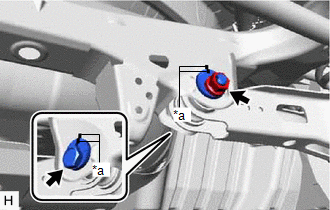
| (a) Place matchmarks on the No. 2 camber adjust cam, rear suspension toe adjust cam sub-assembly and rear suspension member sub-assembly. |
|
(b) Loosen the nut (rear suspension member sub-assembly side) of the rear No. 2 suspension arm assembly.
NOTICE:
Hold the rear suspension toe adjust cam sub-assembly while rotating the nut.
| (c) Using a jack and wooden block, support the rear No. 2 suspension arm assembly. NOTICE:
|
|
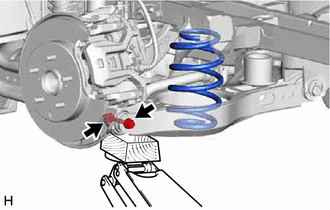
| (d) Remove the bolt and nut, and separate the rear No. 2 suspension arm assembly from the rear axle carrier sub-assembly. NOTICE: Because the nut has its own stopper, do not turn the nut. Loosen the bolt with the nut secured. |
|
(e) Slowly lower the rear No. 2 suspension arm assembly, and then remove the rear coil spring.
6. REMOVE REAR UPPER COIL SPRING INSULATOR
(a) Remove the rear upper coil spring insulator from the vehicle.
7. REMOVE REAR LOWER COIL SPRING INSULATOR
(a) Remove the rear lower coil spring insulator from the rear No. 2 suspension arm assembly.
Toyota Avalon (XX50) 2019-2022 Service & Repair Manual > Can Communication System(for Hv Model): Driving Support ECU Communication Stop Mode. Dtc Check / Clear. ECM Communication Stop Mode
Driving Support ECU Communication Stop Mode DESCRIPTION Detection Item Symptom Trouble Area Driving Support ECU Communication Stop Mode Any of the following conditions are met: Communication stop for "Driving Support (CruiseControl-ACC)" is indicated on the "Communication Bus Check" screen of the Te ...