REMOVAL CAUTION / NOTICE / HINT
The
necessary procedures (adjustment, calibration, initialization, or
registration) that must be performed after parts are removed and
installed, or replaced during rear shock absorber assembly
removal/installation are shown below. Necessary Procedures After Parts Removed/Installed/Replaced (for Gasoline Model:) |
Replaced Part or Performed Procedure |
Necessary Procedure | Effect/Inoperative Function when Necessary Procedure not Performed |
Link | | Rear wheel alignment adjustment |
Perform system variant learning and acceleration sensor zero point calibration. |
- VSC disabled or malfunctioning
- DTCs are output
- Slip indicator light illuminated
- ABS warning light illuminated
|
 | |
Suspension, tires, etc. (The vehicle height changes because of suspension or tire replacement.) |
- Measure ultrasonic sensor detection angle
- Ultrasonic sensor detection angle registration
|
- Intelligent Clearance Sonar System
- Intuitive Parking Assist System
|
| |
Rear television camera assembly optical axis adjustment (Back camera position setting) |
Parking Assist Monitor System |
for Initialization
for Calibration |
- Parking assist ECU initialization
- Adjust steering angle
- Television camera assembly optical axis adjustment (Back camera position setting)
| Panoramic View Monitor System |
for Initialization
for Calibration | Necessary Procedures After Parts Removed/Installed/Replaced (for HV Model:) |
Replaced Part or Performed Procedure |
Necessary Procedure | Effect/Inoperative Function when Necessary Procedure not Performed |
Link | | Rear wheel alignment adjustment |
- Clear zero point calibration data.
- Perform yaw rate and acceleration sensor zero point calibration.
|
- DTCs are stored
- ABS warning light illuminates
- Brake warning light / yellow (minor malfunction) illuminates
- Slip indicator light illuminates
- VSC disabled or malfunctions
|
| |
Suspension, tires, etc. (The vehicle height changes because of suspension or tire replacement.) |
- Measure ultrasonic sensor detection angle
- Ultrasonic sensor detection angle registration
|
- Intelligent Clearance Sonar System
- Intuitive Parking Assist System
|
| |
Rear television camera assembly optical axis adjustment (Back camera position setting) |
Parking Assist Monitor System |
for Initialization
for Calibration |
- Parking assist ECU initialization
- Adjust steering angle
- Television camera assembly optical axis adjustment (Back camera position setting)
| Panoramic View Monitor System |
for Initialization
for Calibration |
HINT:
- Use the same procedure for the RH side and LH side.
- The following procedure is for the LH side.
PROCEDURE 1. REMOVE REAR WHEEL Click here
2. REMOVE NO. 2 FLOOR UNDER COVER (for Gasoline Model)
(a) for LH Side: Click here 3. REMOVE NO. 1 FLOOR UNDER COVER (for Gasoline Model)
(a) for RH Side: Click here 4. LOOSEN REAR SHOCK ABSORBER ASSEMBLY
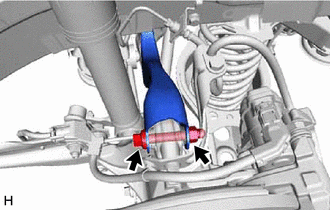
| (a) Loosen the nut of the rear shock absorber assembly. NOTICE:
Hold the rear axle carrier pin while rotating the nut. | |
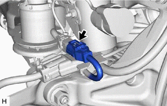
5. SEPARATE NO. 2 PARKING BRAKE WIRE ASSEMBLY (w/ AVS)
| (a) Disconnect the connector. | |
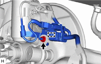
(c) Disengage the clamp and separate the No. 2 parking brake wire assembly.
6. REMOVE REAR STABILIZER LINK ASSEMBLY Click here
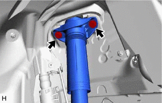
7. SEPARATE REAR SHOCK ABSORBER ASSEMBLY
| (a) Remove the 2 bolts and separate the rear shock absorber assembly from the vehicle. |
|
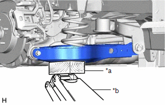
8. SEPARATE REAR UPPER CONTROL ARM ASSEMBLY
| (a) Using a jack and wooden block, support the rear No. 2 suspension arm assembly.
NOTICE:
- When jacking up the rear No. 2 suspension arm assembly, be sure to jack it up slowly.
- Make sure to perform this operation with the vehicle kept as low as possible.
| |
| (b) Remove the bolt and nut, and separate the rear upper control arm assembly from the rear axle carrier sub-assembly.
NOTICE: Because the nut has its own stopper, do not turn the nut. Loosen the bolt with the nut secured. |
|
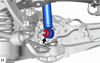
9. REMOVE REAR SHOCK ABSORBER ASSEMBLY
| (a) Remove the nut, plate washer and rear shock absorber assembly from the rear axle carrier sub-assembly.
NOTICE: Hold the rear axle carrier pin while rotating the nut. |
|
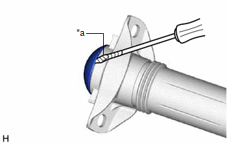
10. REMOVE REAR SHOCK ABSORBER CAP
| (a)
Using a screwdriver with its tip wrapped with protective tape, remove
the rear shock absorber cap from the rear shock absorber assembly. |
|
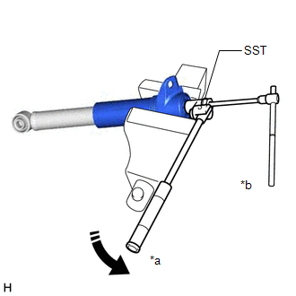
11. REMOVE REAR SUSPENSION SUPPORT ASSEMBLY
| (a) Secure the rear shock absorber assembly in a vise using aluminum plates.
NOTICE: Do not overtighten the vise. | |
(b)
Using SST and a 6 mm hexagon socket wrench, hold the rear shock
absorber rod and remove the rear support to rear shock absorber nut. SST: 09729-97202
(c) Remove the rear suspension support assembly from the rear shock absorber assembly. |