COMPONENTS
ILLUSTRATION

|
*A | for Gasoline Model |
- | - |
|
*1 | NO. 1 FLOOR UNDER COVER |
*2 | NO. 2 FLOOR UNDER COVER |
 |
N*m (kgf*cm, ft.*lbf): Specified torque |
- | - |
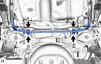
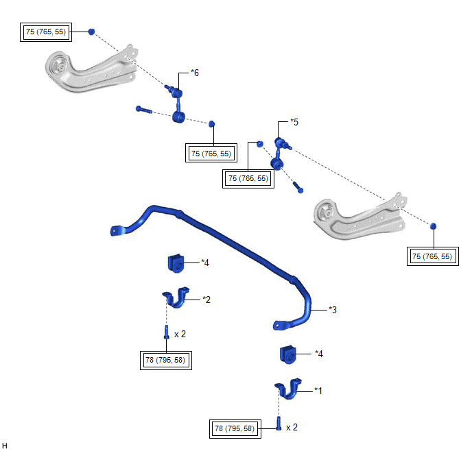
ILLUSTRATION
|
*1 | REAR NO. 1 STABILIZER BAR BRACKET LH |
*2 | REAR NO. 1 STABILIZER BAR BRACKET RH |
|
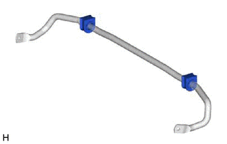
*3 | REAR STABILIZER BAR |
*4 | REAR STABILIZER BUSHING |
|
*5 | REAR STABILIZER LINK ASSEMBLY LH |
*6 | REAR STABILIZER LINK ASSEMBLY RH |
 |
Tightening torque for "Major areas involving basic vehicle performance such as moving/turning/stopping": N*m (kgf*cm, ft.*lbf) |
- | - |
INSPECTION
PROCEDURE
1. INSPECT REAR STABILIZER LINK ASSEMBLY
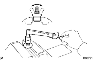
(a) Inspect the turning torque of the ball joint.
(1) Secure the rear stabilizer link assembly in a vise using aluminum plates.
NOTICE:
Do not overtighten the vise.
(2) Install the nut to the rear stabilizer link assembly stud.
(3) Move the stud back and forth several times. Using a torque wrench, turn the stud continuously at a rate of 3 to 5 seconds per turn and take the torque reading on the 5th turn.
Standard Turning Torque:
0.05 to 1.96 N*m (0.6 to 19 kgf*cm, 0.5 to 17 in.*lbf)
HINT:
If the turning torque is not within the specified range, replace the rear stabilizer link assembly with a new one.
(4) Turn the stud to check that the stud does not catch and there is no play.
HINT:
If the stud catches or there is play while turning, replace the rear stabilizer link assembly with a new one.
(b) Inspect the dust cover.
(1) Check that the dust cover is not cracked and that there is no grease on it.
HINT:
If the dust cover is cracked or there is grease on it, replace the rear stabilizer link assembly with a new one.
INSTALLATION
PROCEDURE
1. INSTALL REAR STABILIZER BUSHING
(a) Install the 2 rear stabilizer bushings to the rear stabilizer bar.
NOTICE:
Be sure to install the rear stabilizer bushings so that each cutout faces the front of the vehicle.
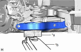
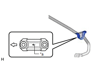
2. INSTALL REAR NO. 1 STABILIZER BAR BRACKET LH
(a) Install the rear No. 1 stabilizer bar bracket LH to the rear stabilizer bushing.
NOTICE:
Be sure to install the rear No. 1 stabilizer bar bracket LH so that each arrow mark faces the front of the vehicle.
|
*a | Arrow Mark |
 |
Front of the Vehicle |
3. INSTALL REAR NO. 1 STABILIZER BAR BRACKET RH
HINT:
Perform the same procedure as for the LH side.
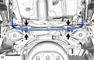
4. INSTALL REAR STABILIZER BAR
| (a) Install the rear stabilizer bar, rear No. 1 stabilizer bar bracket LH, rear No. 1 stabilizer bar bracket RH and 2 rear stabilizer bushings to the rear suspension member sub-assembly with the 4 bolts. Torque: 78 N·m {795 kgf·cm, 58 ft·lbf} NOTICE:
|
|
5. STABILIZE SUSPENSION
Click here 
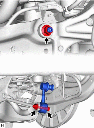
6. INSTALL REAR STABILIZER LINK ASSEMBLY LH
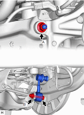
| (a) Install the rear stabilizer link assembly LH with the nut (A). Torque: 75 N·m {765 kgf·cm, 55 ft·lbf} HINT: If the ball joint turns together with the nut, use a 6 mm hexagon socket wrench to hold the stud bolt. |
|
(b) Install the rear stabilizer link assembly LH with the bolt and nut (B).
Torque:
75 N·m {765 kgf·cm, 55 ft·lbf}
NOTICE:
Because the bolt has its own stopper, do not turn the bolt. Tighten the nut with the bolt secured.
7. INSTALL REAR STABILIZER LINK ASSEMBLY RH
HINT:
Perform the same procedure as for the LH side.
8. INSTALL CENTER EXHAUST PIPE ASSEMBLY
for 2GR-FKS: Click here
for A25A-FXS: Click here
9. INSTALL NO. 1 FLOOR UNDER COVER (for Gasoline Model)
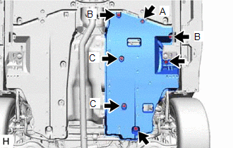
| (a) Install the No. 1 floor under cover with the 2 grommets (B) and 2 clips (C). Torque: Grommet (B) : 7.5 N·m {76 kgf·cm, 66 in·lbf} |
|
(b) Install the 2 bolts and clip (A).
Torque:
Bolt :
7.5 N·m {76 kgf·cm, 66 in·lbf}
10. INSTALL NO. 2 FLOOR UNDER COVER (for Gasoline Model)
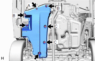
| (a) Install the No. 2 floor under cover with the 2 grommets (B) and 2 clips (C). Torque: Grommet (B) : 7.5 N·m {76 kgf·cm, 66 in·lbf} |
|
(b) Install the 2 bolts and clip (A).
Torque:
Bolt :
7.5 N·m {76 kgf·cm, 66 in·lbf}
11. INSTALL REAR WHEEL
Click here
12. INSPECT FOR EXHAUST GAS LEAK
for 2GR-FKS: Click here
for A25A-FXS: Click here
REMOVAL
CAUTION / NOTICE / HINT
The necessary procedures (adjustment, calibration, initialization, or registration) that must be performed after parts are removed and installed, or replaced during rear stabilizer bar removal/installation are shown below.
Necessary Procedures After Parts Removed/Installed/Replaced (for Gasoline Model:)|
Replaced Part or Performed Procedure |
Necessary Procedure | Effect/Inoperative Function when Necessary Procedure not Performed |
Link |
|---|---|---|---|
| Gas leak from exhaust system is repaired |
Inspection After Repair |
|
|
|
Replaced Part or Performed Procedure |
Necessary Procedure | Effect/Inoperative Function when Necessary Procedure not Performed |
Link |
|---|---|---|---|
| Gas leak from exhaust system is repaired |
Inspection After Repair |
|
|
CAUTION:
To prevent burns, do not touch the engine, exhaust pipe or other high temperature components while the engine is hot.
PROCEDURE
1. REMOVE REAR WHEEL
Click here 
2. REMOVE NO. 2 FLOOR UNDER COVER (for Gasoline Model)
| (a) Remove the 2 bolts and clip (A). |
|
(b) Disengage the 2 grommets (B) and 2 clips (C) to remove the No. 2 floor under cover.
3. REMOVE NO. 1 FLOOR UNDER COVER (for Gasoline Model)
| (a) Remove the 2 bolts and clip (A). |
|
(b) Disengage the 2 grommets (B) and 2 clips (C) to remove the No. 1 floor under cover.
4. REMOVE CENTER EXHAUST PIPE ASSEMBLY
for 2GR-FKS: Click here
for A25A-FXS: Click here
5. REMOVE REAR STABILIZER LINK ASSEMBLY LH
| (a) Loosen the nut (A) of the rear stabilizer link assembly LH. HINT: If the ball joint turns together with the nut, use a 6 mm hexagon socket wrench to hold the stud bolt. |
|
(b) Loosen the nut (B) of the rear stabilizer link assembly LH.
NOTICE:
Because the bolt has its own stopper, do not turn the bolt. Loosen the nut with the bolt secured.
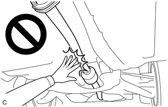
| (c) Using a jack and wooden block, support the rear No. 2 suspension arm assembly. NOTICE:
|
|
| (d) Remove the bolt, 2 nuts and rear stabilizer link assembly LH. |
|
6. REMOVE REAR STABILIZER LINK ASSEMBLY RH
HINT:
Perform the same procedure as for the LH side.
7. REMOVE REAR STABILIZER BAR
| (a) Remove the 4 bolts, rear stabilizer bar, rear No. 1 stabilizer bar bracket LH, rear No. 1 stabilizer bar bracket RH and 2 rear stabilizer bushings from the rear suspension member sub-assembly. |
|
8. REMOVE REAR NO. 1 STABILIZER BAR BRACKET LH
(a) Remove the rear No. 1 stabilizer bar bracket LH from the rear stabilizer bushing.
9. REMOVE REAR NO. 1 STABILIZER BAR BRACKET RH
HINT:
Perform the same procedure as for the LH side.
10. REMOVE REAR STABILIZER BUSHING
| (a) Remove the 2 rear stabilizer bushings from the rear stabilizer bar. |
|
Toyota Avalon (XX50) 2019-2022 Service & Repair Manual > Automatic Transaxle System: Pressure Control Solenoid "G" Circuit Short to Battery (P280712). Pressure Control Solenoid "G" Circuit Short to Ground or Open (P280714). Pressure Control Solenoid "H" Circuit Short to Battery (P2816
Pressure Control Solenoid "G" Circuit Short to Battery (P280712) DESCRIPTION Changing gears is performed by the ECM turning the solenoid (SL1, SL2, SL3, SL4, SL5 and SL6) valves on and off. If an open or short occurs in any of the solenoid valve circuits, the ECM controls the remaining normal soleno ...