COMPONENTS
ILLUSTRATION
|
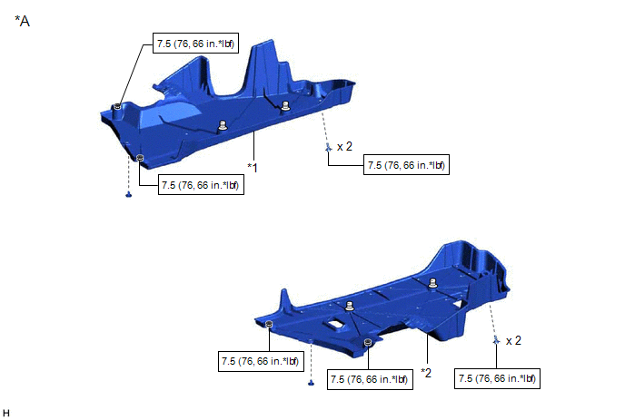
*A | for Gasoline Model |
- | - |
|
*1 | NO. 1 FLOOR UNDER COVER |
*2 | NO. 2 FLOOR UNDER COVER |
 |
N*m (kgf*cm, ft.*lbf): Specified torque |
- | - |
ILLUSTRATION
|
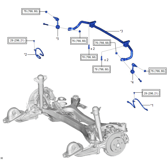
*1 | REAR FLEXIBLE HOSE LH |
*2 | REAR FLEXIBLE HOSE RH |
|
*3 | REAR STABILIZER BAR |
*4 | REAR STABILIZER LINK ASSEMBLY LH |
|
*5 | REAR STABILIZER LINK ASSEMBLY RH |
- | - |
 |
Tightening torque for "Major areas involving basic vehicle performance such as moving/turning/stopping": N*m (kgf*cm, ft.*lbf) |
- | - |
ILLUSTRATION
|
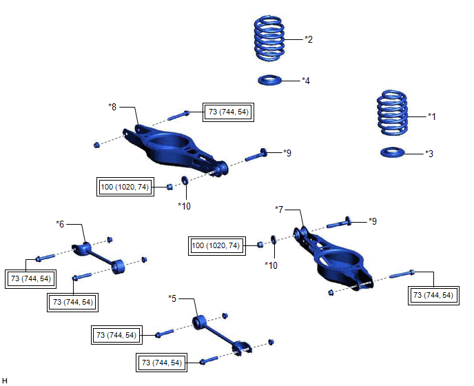
*1 | REAR COIL SPRING LH |
*2 | REAR COIL SPRING RH |
|
*3 | REAR LOWER COIL SPRING INSULATOR LH |
*4 | REAR LOWER COIL SPRING INSULATOR RH |
|
*5 | REAR NO. 1 SUSPENSION ARM ASSEMBLY LH |
*6 | REAR NO. 1 SUSPENSION ARM ASSEMBLY RH |
|
*7 | REAR NO. 2 SUSPENSION ARM ASSEMBLY LH |
*8 | REAR NO. 2 SUSPENSION ARM ASSEMBLY RH |
|
*9 | REAR SUSPENSION TOE ADJUST CAM SUB-ASSEMBLY |
*10 | NO. 2 CAMBER ADJUST CAM |
|
|
Tightening torque for "Major areas involving basic vehicle performance such as moving/turning/stopping": N*m (kgf*cm, ft.*lbf) |
- | - |
ILLUSTRATION
|
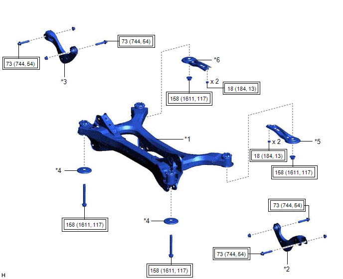
*1 | REAR SUSPENSION MEMBER SUB-ASSEMBLY |
*2 | REAR UPPER CONTROL ARM ASSEMBLY LH |
|
*3 | REAR UPPER CONTROL ARM ASSEMBLY RH |
*4 | REAR SUSPENSION MEMBER LOWER STOPPER |
|
*5 | REAR SUSPENSION MEMBER LOWER BRACE LH |
*6 | REAR SUSPENSION MEMBER LOWER BRACE RH |
|
|
Tightening torque for "Major areas involving basic vehicle performance such as moving/turning/stopping": N*m (kgf*cm, ft.*lbf) |
- | - |
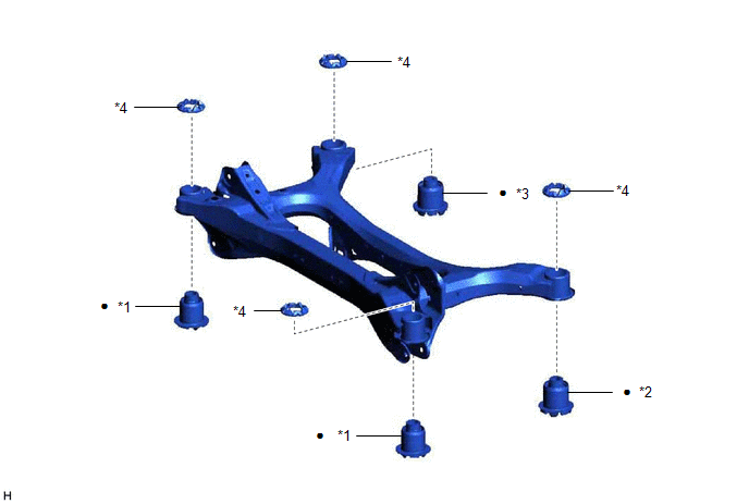
ILLUSTRATION
|
*1 | REAR SUSPENSION MEMBER FRONT BODY MOUNTING CUSHION |
*2 | REAR SUSPENSION MEMBER REAR BODY MOUNT CUSHION LH |
|
*3 | REAR SUSPENSION MEMBER REAR BODY MOUNT CUSHION RH |
*4 | REAR SUSPENSION MEMBER CUSHION |
|
● | Non-reusable part |
- | - |
INSTALLATION
PROCEDURE
1. INSTALL REAR SUSPENSION MEMBER FRONT BODY MOUNTING CUSHION (for LH Side)
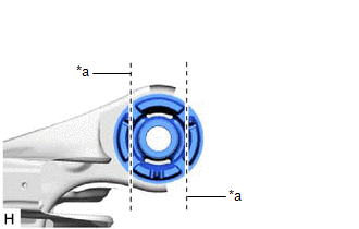
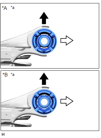
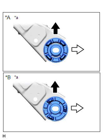
(a) Confirm the installation direction and temporarily install a new rear suspension member front body mounting cushion.
NOTICE:
|
*A | Type A |
|
*B | Type B |
|
*a | View from Underneath |
 |
Front of the Vehicle |
 |
Outside of the Vehicle |
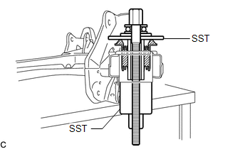
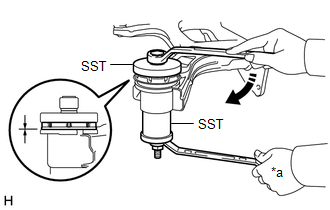
| (b) Install SST as shown in the illustration. SST: 09570-24011 SST: 09830-10010 09830-01010 09830-01020 09830-01040 09830-01050 NOTICE: Apply molybdenum grease to the threads and tip of the SST center bolt before use. |
|
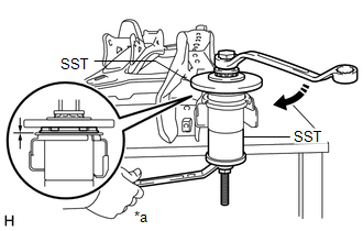
(c) Using SST, install the rear suspension member front body mounting cushion until there is no clearance between the rear suspension member sub-assembly and rear suspension member front body mounting cushion.
SST: 09570-24011
SST: 09830-10010
09830-01010
09830-01020
09830-01040
09830-01050
NOTICE:
If the rear suspension member sub-assembly is scratched, apply paint to the scratched areas of the rear suspension member sub-assembly.
|
*a | Hold |
 |
Turn |
(d) Remove SST from the rear suspension member sub-assembly.
2. INSTALL REAR SUSPENSION MEMBER FRONT BODY MOUNTING CUSHION (for RH Side)
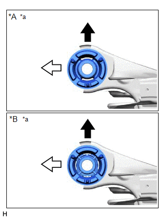
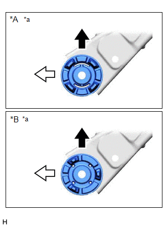
(a) Confirm the installation direction and temporarily install a new rear suspension member front body mounting cushion.
NOTICE:
|
*A | Type A |
|
*B | Type B |
|
*a | View from Underneath |
|
|
Front of the Vehicle |
|
|
Outside of the Vehicle |
(b) Install SST using the same procedure as for the rear suspension member front body mounting cushion (for LH Side).
SST: 09570-24011
SST: 09830-10010
09830-01010
09830-01020
09830-01040
09830-01050
NOTICE:
Apply molybdenum grease to the threads and tip of the SST center bolt before use.
(c) Using SST, install the rear suspension member front body mounting cushion until there is no clearance between the rear suspension member sub-assembly and rear suspension member front body mounting cushion.
SST: 09570-24011
SST: 09830-10010
09830-01010
09830-01020
09830-01040
09830-01050
NOTICE:
If the rear suspension member sub-assembly is scratched, apply paint to the scratched areas of the rear suspension member sub-assembly.
HINT:
Perform the same procedure as for the rear suspension member front body mounting cushion (for LH Side).
(d) Remove SST from the rear suspension member sub-assembly.
3. INSTALL REAR SUSPENSION MEMBER REAR BODY MOUNT CUSHION LH
(a) Confirm the installation direction and temporarily install a new rear suspension member rear body mount cushion LH.
NOTICE:
|
*A | Type A |
|
*B | Type B |
|
*a | View from Underneath |
|
|
Front of the Vehicle |
|
|
Outside of the Vehicle |
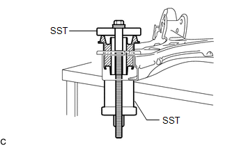
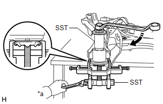
| (b) Install SST as shown in the illustration. SST: 09710-28031 09711-02030 09711-02040 94622-51200 SST: 09950-60021 09951-00720 09951-00890 NOTICE: Apply molybdenum grease to the threads and tip of the SST center bolt before use. |
|
(c) Using SST, install the rear suspension member rear body mount cushion LH until there is no clearance between the rear suspension member sub-assembly and rear suspension member rear body mount cushion LH.
SST: 09710-28031
09711-02030
09711-02040
94622-51200
SST: 09950-60021
09951-00720
09951-00890
NOTICE:
If the rear suspension member sub-assembly is scratched, apply paint to the scratched areas of the rear suspension member sub-assembly.
|
*a | Hold |
|
|
Turn |
(d) Remove SST from the rear suspension member sub-assembly.
4. INSTALL REAR SUSPENSION MEMBER REAR BODY MOUNT CUSHION RH
(a) Confirm the installation direction and temporarily install a new rear suspension member rear body mount cushion RH.
NOTICE:
|
*A | Type A |
|
*B | Type B |
|
*a | View from Underneath |
|
|
Front of the Vehicle |
|
|
Outside of the Vehicle |
(b) Install SST using the same procedure as for the rear suspension member rear body mount cushion LH.
SST: 09710-28031
09711-02030
09711-02040
94622-51200
SST: 09950-60021
09951-00720
09951-00890
NOTICE:
Apply molybdenum grease to the threads and tip of the SST center bolt before use.
(c) Using SST, install the rear suspension member rear body mount cushion RH until there is no clearance between the rear suspension member sub-assembly and rear suspension member rear body mount cushion RH.
SST: 09710-28031
09711-02030
09711-02040
94622-51200
SST: 09950-60021
09951-00720
09951-00890
NOTICE:
If the rear suspension member sub-assembly is scratched, apply paint to the scratched areas of the rear suspension member sub-assembly.
HINT:
Perform the same procedure as for the rear suspension member rear body mount cushion LH.
(d) Remove SST from the rear suspension member sub-assembly.
5. INSTALL REAR UPPER CONTROL ARM ASSEMBLY LH
Click here 
6. INSTALL REAR UPPER CONTROL ARM ASSEMBLY RH
HINT:
Perform the same procedure as for the LH side.
7. INSTALL REAR SUSPENSION MEMBER SUB-ASSEMBLY
(a) Install the 4 rear suspension member cushions to the rear suspension member sub-assembly.
HINT:
When reusing the rear suspension member cushion, make sure to check its identification mark and install it to the correct position.
(b) Using an engine lifter and 4 attachments or equivalent tools, support the rear suspension member sub-assembly as shown in the illustration.
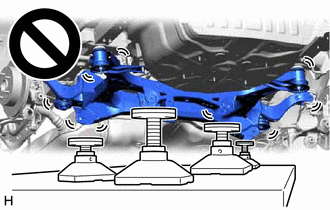
NOTICE:
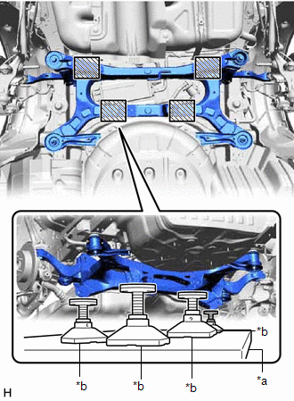
|
*a | Engine Lifter |
|
*b | Attachment |
 |
Attachment Placement Location |
(c) Raise the rear suspension member sub-assembly until there is no clearance between the rear suspension member sub-assembly and vehicle.
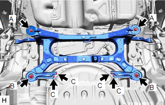
| (d) Install the rear suspension member sub-assembly with the 2 rear suspension member lower stoppers, rear suspension member lower brace LH and rear suspension member lower brace RH, 2 bolts and 6 nuts. Torque: Bolt A : 158 N·m {1611 kgf·cm, 117 ft·lbf} Nut B : 158 N·m {1611 kgf·cm, 117 ft·lbf} Nut C : 18 N·m {184 kgf·cm, 13 ft·lbf} |
|
8. TEMPORARILY INSTALL REAR UPPER CONTROL ARM ASSEMBLY LH
(a) Temporarily install the rear upper control arm assembly LH to the rear axle carrier sub-assembly LH with the bolt and nut.
NOTICE:
9. TEMPORARILY INSTALL REAR UPPER CONTROL ARM ASSEMBLY RH
HINT:
Perform the same procedure as for the LH side.
10. TEMPORARILY INSTALL REAR NO. 1 SUSPENSION ARM ASSEMBLY LH
Click here
11. TEMPORARILY INSTALL REAR NO. 1 SUSPENSION ARM ASSEMBLY RH
HINT:
Perform the same procedure as for the LH side.
12. TEMPORARILY INSTALL REAR NO. 2 SUSPENSION ARM ASSEMBLY LH
Click here
13. TEMPORARILY INSTALL REAR NO. 2 SUSPENSION ARM ASSEMBLY RH
HINT:
Perform the same procedure as for the LH side.
14. INSTALL REAR LOWER COIL SPRING INSULATOR LH
Click here
15. INSTALL REAR LOWER COIL SPRING INSULATOR RH
HINT:
Perform the same procedure as for the LH side.
16. INSTALL REAR COIL SPRING LH
Click here
17. INSTALL REAR COIL SPRING RH
HINT:
Perform the same procedure as for the LH side.
18. INSTALL REAR STABILIZER BAR
Click here
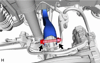
19. CONNECT REAR FLEXIBLE HOSE LH
(a) Connect the rear flexible hose LH to the rear flexible hose bracket with the bolt.
Torque:
29 N·m {296 kgf·cm, 21 ft·lbf}
20. CONNECT REAR FLEXIBLE HOSE RH
HINT:
Perform the same procedure as for the LH side.
21. STABILIZE SUSPENSION
Click here
22. INSTALL REAR STABILIZER LINK ASSEMBLY LH
Click here
23. INSTALL REAR STABILIZER LINK ASSEMBLY RH
HINT:
Perform the same procedure as for the LH side.
24. INSTALL REAR NO. 1 SUSPENSION ARM ASSEMBLY LH
Click here
25. INSTALL REAR NO. 1 SUSPENSION ARM ASSEMBLY RH
HINT:
Perform the same procedure as for the LH side.
26. INSTALL REAR NO. 2 SUSPENSION ARM ASSEMBLY LH
(a) Install the rear No. 2 suspension arm assembly LH (rear axle carrier sub-assembly side) with the bolt.
Click here
27. INSTALL REAR NO. 2 SUSPENSION ARM ASSEMBLY RH
HINT:
Perform the same procedure as for the LH side.
28. INSTALL REAR UPPER CONTROL ARM ASSEMBLY LH
(a) Install the rear upper control arm assembly LH to the rear axle carrier sub-assembly LH with the bolt.
Torque:
73 N·m {744 kgf·cm, 54 ft·lbf}
NOTICE:
Because the nut has its own stopper, do not turn the nut. Tighten the bolt with the nut secured.
29. INSTALL REAR UPPER CONTROL ARM ASSEMBLY RH
HINT:
Perform the same procedure as for the LH side.
30. INSTALL CENTER EXHAUST PIPE ASSEMBLY
for 2GR-FKS: Click here
for A25A-FXS: Click here
31. INSTALL NO. 1 FLOOR UNDER COVER (for Gasoline Model)
Click here
32. INSTALL NO. 2 FLOOR UNDER COVER (for Gasoline Model)
Click here
33. INSTALL REAR WHEEL
Click here
34. INSTALL REAR NO. 2 SUSPENSION ARM ASSEMBLY LH
(a) Install the rear No. 2 suspension arm assembly LH (rear suspension member sub-assembly side) with the nut.
Click here
35. INSTALL REAR NO. 2 SUSPENSION ARM ASSEMBLY RH
HINT:
Perform the same procedure as for the LH side.
36. INSPECT FOR EXHAUST GAS LEAK
for 2GR-FKS: Click here
for A25A-FXS: Click here
37. INSPECT AND ADJUST REAR WHEEL ALIGNMENT
Click here
38. PERFORM INITIALIZATION
for Gasoline Model:
|
|
|
Parking Assist Monitor System |
|
|
Panoramic View Monitor System |
|
|
|
|
Parking Assist Monitor System |
|
|
Panoramic View Monitor System |
|
REMOVAL
CAUTION / NOTICE / HINT
The necessary procedures (adjustment, calibration, initialization, or registration) that must be performed after parts are removed and installed, or replaced during rear suspension member sub-assembly removal/installation are shown below.
Necessary Procedures After Parts Removed/Installed/Replaced (for Gasoline Model:)|
Replaced Part or Performed Procedure |
Necessary Procedure | Effect/Inoperative Function when Necessary Procedure not Performed |
Link |
|---|---|---|---|
| Rear wheel alignment adjustment |
Perform system variant learning and acceleration sensor zero point calibration. |
|
|
|
Suspension, tires, etc. (The vehicle height changes because of suspension or tire replacement.) |
|
|
|
|
Rear television camera assembly optical axis adjustment (Back camera position setting) |
Parking Assist Monitor System |
| |
| Panoramic View Monitor System |
| |
|
Gas leak from exhaust system is repaired |
Inspection After Repair |
|
|
|
Replaced Part or Performed Procedure |
Necessary Procedure | Effect/Inoperative Function when Necessary Procedure not Performed |
Link |
|---|---|---|---|
| Rear wheel alignment adjustment |
|
|
|
|
Suspension, tires, etc. (The vehicle height changes because of suspension or tire replacement.) |
|
|
|
|
Rear television camera assembly optical axis adjustment (Back camera position setting) |
Parking Assist Monitor System |
| |
| Panoramic View Monitor System |
| |
|
Gas leak from exhaust system is repaired |
Inspection After Repair |
|
|
CAUTION:
To prevent burns, do not touch the engine, exhaust pipe or other high temperature components while the engine is hot.
PROCEDURE
1. REMOVE REAR WHEEL
Click here 
2. REMOVE NO. 2 FLOOR UNDER COVER (for Gasoline Model)
Click here
3. REMOVE NO. 1 FLOOR UNDER COVER (for Gasoline Model)
Click here
4. REMOVE CENTER EXHAUST PIPE ASSEMBLY
for 2GR-FKS: Click here
for A25A-FXS: Click here
5. SEPARATE REAR FLEXIBLE HOSE LH
(a) Remove the bolt and separate the rear flexible hose LH from the rear flexible hose bracket.
6. SEPARATE REAR FLEXIBLE HOSE RH
HINT:
Perform the same procedure as for the LH side.
7. REMOVE REAR STABILIZER LINK ASSEMBLY LH
Click here
8. REMOVE REAR STABILIZER LINK ASSEMBLY RH
HINT:
Perform the same procedure as for the LH side.
9. REMOVE REAR STABILIZER BAR
Click here
10. REMOVE REAR COIL SPRING LH
Click here
11. REMOVE REAR COIL SPRING RH
HINT:
Perform the same procedure as for the LH side.
12. REMOVE REAR LOWER COIL SPRING INSULATOR LH
Click here
13. REMOVE REAR LOWER COIL SPRING INSULATOR RH
HINT:
Perform the same procedure as for the LH side.
14. REMOVE REAR NO. 2 SUSPENSION ARM ASSEMBLY LH
Click here
15. REMOVE REAR NO. 2 SUSPENSION ARM ASSEMBLY RH
HINT:
Perform the same procedure as for the LH side.
16. REMOVE REAR NO. 1 SUSPENSION ARM ASSEMBLY LH
Click here
17. REMOVE REAR NO. 1 SUSPENSION ARM ASSEMBLY RH
HINT:
Perform the same procedure as for the LH side.
18. SEPARATE REAR UPPER CONTROL ARM ASSEMBLY LH
| (a) Remove the bolt and nut and separate the rear upper control arm assembly LH from the rear axle carrier sub-assembly LH. NOTICE: Because the nut has its own stopper, do not turn the nut. Loosen the bolt with the nut secured. |
|
19. SEPARATE REAR UPPER CONTROL ARM ASSEMBLY RH
HINT:
Use the same procedure as for the LH side.
20. REMOVE REAR SUSPENSION MEMBER SUB-ASSEMBLY
(a) Using an engine lifter and 4 attachments or equivalent tools, support the rear suspension member sub-assembly as shown in the illustration.

NOTICE:
Use attachments or equivalent tools to keep the rear suspension member sub-assembly level.

|
*a | Engine Lifter |
|
*b | Attachment |
 |
Attachment Placement Location |
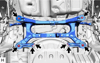
| (b) Remove the 2 bolts, 6 nuts, 2 rear suspension member lower stoppers, rear suspension member lower brace LH and rear suspension member lower brace RH. |
|
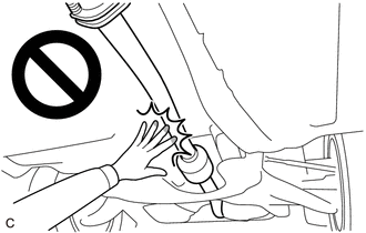
(c) Slowly lower the rear suspension member sub-assembly.
NOTICE:
When lowering the rear suspension member sub-assembly, be careful not to damage the vehicle body or other components installed to the vehicle.
(d) Remove the 4 rear suspension member cushions from the rear suspension member sub-assembly.
HINT:
Make sure to place an identification mark on the rear suspension member cushion so that they can be reinstalled to their original positions.
21. REMOVE REAR UPPER CONTROL ARM ASSEMBLY LH
Click here
22. REMOVE REAR UPPER CONTROL ARM ASSEMBLY RH
HINT:
Perform the same procedure as for the LH side.
23. REMOVE REAR SUSPENSION MEMBER FRONT BODY MOUNTING CUSHION (for LH Side)
| (a) Using a chisel and hammer, bend the 2 portions of the rear suspension member front body mounting cushion rib. NOTICE: Make sure to bend the 2 portions of the cushion rib until the claws of SST can fit securely. |
|
(b) Apply lubricant to the contact surfaces of the rear suspension member front body mounting cushion.
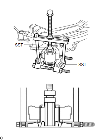
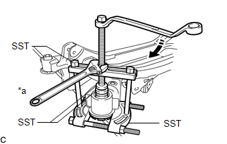
| (c) Install SST as shown in the illustration. SST: 09830-10010 09830-01010 09830-01040 09830-01050 SST: 09950-40011 09951-04010 09952-04010 09954-04010 09955-04061 09958-04011 NOTICE: Apply molybdenum grease to the threads and tip of the SST center bolt before use. |
|
(d) Using SST, remove the rear suspension member front body mounting cushion while applying lubricant into the clearance between the rear suspension member front body mounting cushion and the rear suspension member sub-assembly.
SST: 09830-10010
09830-01010
09830-01040
09830-01050
SST: 09950-40011
09951-04010
09952-04010
09954-04010
09955-04061
09958-04011
NOTICE:
|
*a | Hold |
 |
Turn |
(e) Remove SST and the rear suspension member front body mounting cushion from the rear suspension member sub-assembly.
24. REMOVE REAR SUSPENSION MEMBER FRONT BODY MOUNTING CUSHION (for RH Side)
HINT:
Perform the same procedure as for the LH side.
25. REMOVE REAR SUSPENSION MEMBER REAR BODY MOUNT CUSHION LH
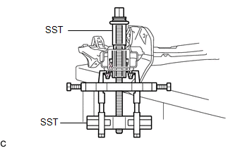
| (a) Install SST as shown in the illustration. SST: 09950-00020 SST: 09950-00030 SST: 09950-60011 09951-00330 NOTICE: Apply molybdenum grease to the threads and tip of the SST center bolt before use. |
|
(b) Using SST, remove the rear suspension member rear body mount cushion LH while applying lubricant into the clearance between the rear suspension member rear body mount cushion LH and the rear suspension member sub-assembly.
SST: 09950-00020
SST: 09950-00030
SST: 09950-60011
09951-00330
NOTICE:
|
*a | Hold |
|
|
Turn |
(c) Remove SST and the rear suspension member rear body mount cushion LH from the rear suspension member sub-assembly.
26. REMOVE REAR SUSPENSION MEMBER REAR BODY MOUNT CUSHION RH
HINT:
Perform the same procedure as for the LH side.
Toyota Avalon (XX50) 2019-2022 Service & Repair Manual > Can Communication System(for Gasoline Model): Headup Display Communication Stop Mode. How To Proceed With Troubleshooting. Millimeter Wave Radar Sensor Communication Stop Mode
Headup Display Communication Stop Mode DESCRIPTION Detection Item Symptom Trouble Area Headup Display Communication Stop Mode Any of the following conditions are met: Communication stop for "Head Up Display" is indicated on the "Communication Bus Check" screen of the Techstream. Click here Communica ...