COMPONENTS
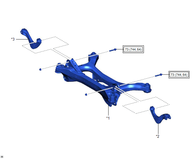
ILLUSTRATION
|
*1 | REAR SUSPENSION MEMBER SUB-ASSEMBLY |
*2 | REAR UPPER CONTROL ARM ASSEMBLY LH |
|
*3 | REAR UPPER CONTROL ARM ASSEMBLY RH |
- | - |
 |
Tightening torque for "Major areas involving basic vehicle performance such as moving/turning/stopping": N*m (kgf*cm, ft.*lbf) |
- | - |
INSTALLATION
PROCEDURE
1. INSTALL REAR UPPER CONTROL ARM ASSEMBLY LH
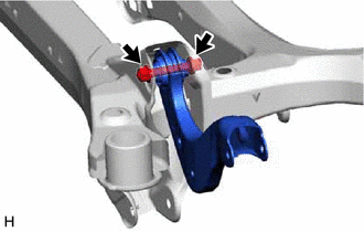
| (a) Temporarily install the rear upper control arm assembly LH to the rear suspension member sub-assembly with the bolt and nut. NOTICE:
|
|
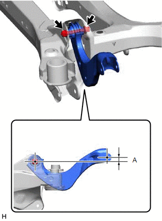
(b) Position the rear upper control arm assembly LH as shown in the illustration.
Reference Length (A):
1.2 mm (0.0472 in.)
(c) Fully tighten the bolt.
Torque:
73 N·m {744 kgf·cm, 54 ft·lbf}
NOTICE:
Because the nut has its own stopper, do not turn the nut. Tighten the bolt with the nut secured.
2. INSTALL REAR UPPER CONTROL ARM ASSEMBLY RH
HINT:
Perform the same procedure as for the LH side.
3. INSTALL REAR SUSPENSION MEMBER SUB-ASSEMBLY
Click here

REMOVAL
CAUTION / NOTICE / HINT
The necessary procedures (adjustment, calibration, initialization, or registration) that must be performed after parts are removed and installed, or replaced during rear upper control arm assembly removal/installation are shown below.
Necessary Procedures After Parts Removed/Installed/Replaced (for Gasoline Model:)|
Replaced Part or Performed Procedure |
Necessary Procedure | Effect/Inoperative Function when Necessary Procedure not Performed |
Link |
|---|---|---|---|
| Rear wheel alignment adjustment |
Perform system variant learning and acceleration sensor zero point calibration. |
|
|
|
Suspension, tires, etc. (The vehicle height changes because of suspension or tire replacement.) |
|
|
|
|
Rear television camera assembly optical axis adjustment (Back camera position setting) |
Parking Assist Monitor System |
| |
| Panoramic View Monitor System |
| |
|
Gas leak from exhaust system is repaired |
Inspection After Repair |
|
|
|
Replaced Part or Performed Procedure |
Necessary Procedure | Effect/Inoperative Function when Necessary Procedure not Performed |
Link |
|---|---|---|---|
| Rear wheel alignment adjustment |
|
|
|
|
Suspension, tires, etc. (The vehicle height changes because of suspension or tire replacement.) |
|
|
|
|
Rear television camera assembly optical axis adjustment (Back camera position setting) |
Parking Assist Monitor System |
| |
| Panoramic View Monitor System |
| |
|
Gas leak from exhaust system is repaired |
Inspection After Repair |
|
|
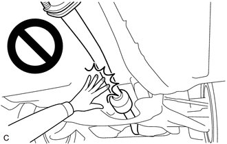
CAUTION:
To prevent burns, do not touch the engine, exhaust pipe or other high temperature components while the engine is hot.
PROCEDURE
1. REMOVE REAR SUSPENSION MEMBER SUB-ASSEMBLY
Click here 
2. REMOVE REAR UPPER CONTROL ARM ASSEMBLY LH
| (a) Remove the bolt, nut and rear upper control arm assembly LH from the rear suspension member sub-assembly. NOTICE: Because the nut has its own stopper, do not turn the nut. Loosen the bolt with the nut secured. |
|
3. REMOVE REAR UPPER CONTROL ARM ASSEMBLY RH
HINT:
Perform the same procedure as for the LH side.
Toyota Avalon (XX50) 2019-2022 Service & Repair Manual > Navigation System(for Gasoline Model): Radio Receiver Power Source Circuit. Registered Device cannot be Deleted. Reverse Signal Circuit between Radio Receiver Assembly and Navigation ECU
Radio Receiver Power Source Circuit DESCRIPTION This is the power source circuit to operate the radio and display receiver assembly. WIRING DIAGRAM CAUTION / NOTICE / HINT NOTICE: Inspect the fuses for circuits related to this system before performing the following procedure. PROCEDURE 1. CHECK HARN ...