DESCRIPTION
The acceleration sensor (up and down G sensor) detects the upward and downward acceleration of the vehicle and outputs it as a voltage to the absorber control ECU.
The 3 up and down G sensors are installed in the driver side instrument panel, the passenger side instrument panel and the absorber control ECU.
Each up and down G sensor independently detects the upward and downward acceleration of the vehicle.
During a test mode inspection, the absorber control ECU reads the fluctuations in each sensor signal.
When a sensor signal does not fluctuate, test mode DTCs C1796, C1797 and C1798 remain stored.
|
DTC No. | Detection Item |
DTC Detection Condition | Trouble Area |
Warning Indicate | Memory |
|---|---|---|---|---|---|
|
C1715 | Front Acceleration Sensor RH Malfunction |
One of the following conditions is met:
|
| Does not come on |
Yes |
| C1716 |
Front Acceleration Sensor LH Malfunction |
One of the following conditions is met:
|
| Does not come on |
Yes |
| C1717 |
Rear Acceleration Sensor Malfunction |
One of the following conditions is met:
| Absorber control ECU |
Does not come on | Yes |
|
C1796 | (Up&Down)G Sensor FR |
With the vehicle stationary on a level surface, an acceleration sensor value that is within -1.96 to 1.96 m/s2 is not received from the acceleration sensor assembly RH for 1 second or more. |
| Test mode |
(Test mode) |
|
C1797 | (Up&Down)G Sensor FL |
With the vehicle stationary on a level surface, an acceleration sensor value that is within -1.96 to 1.96 m/s2 is not received from the acceleration sensor assembly LH for 1 second or more. |
| Test mode |
(Test mode) |
|
C1798 | (Up&Down)G Sensor Rear |
With the vehicle stationary on a level surface, an acceleration sensor value that is within -1.96 to 1.96 m/s2 is not received from the rear acceleration sensor (absorber control ECU) for 1 second or more. |
Absorber control ECU |
Test mode | (Test mode) |
|
Vehicle Condition | ||||||
|---|---|---|---|---|---|---|
|
Pattern 1 | Pattern 2 |
Pattern 3 | Pattern 4 |
Pattern 5 | ||
|
Diagnosis Condition | Engine switch is on (IG) |
○ | ○ |
○ | ○ |
○ |
|
Malfunction Status | Sensor power source voltage is 4.3 V or less |
○ | - |
- | - |
- |
| Sensor power source voltage is 5.5 V or higher |
- | ○ |
- | - |
- | |
| Output voltage is 0.3 V or less |
- | - |
○ | - |
- | |
| Output voltage is 4.7 V or higher |
- | - |
- | ○ |
- | |
| Sensor output value is +/- 0.0639 m/s2 |
- | - |
- | - |
○ | |
|
Detection Time | 0.5 seconds or more |
0.5 seconds or more | 1 second or more |
1 second or more | 300 seconds or more | |
|
Number of Trips | 1 trip |
1 trip | 1 trip |
1 trip | 1 trip | |
HINT:
DTC will be stored when the conditions of any pattern in the table above are met.
DTC Detection Conditions: C1716|
Vehicle Condition | ||||||
|---|---|---|---|---|---|---|
|
Pattern 1 | Pattern 2 |
Pattern 3 | Pattern 4 |
Pattern 5 | ||
|
Diagnosis Condition | Engine switch is on (IG) |
○ | ○ |
○ | ○ |
○ |
|
Malfunction Status | Sensor power source voltage is 4.3 V or less |
○ | - |
- | - |
- |
| Sensor power source voltage is 5.5 V or higher |
- | ○ |
- | - |
- | |
| Output voltage is 0.3 V or less |
- | - |
○ | - |
- | |
| Output voltage is 4.7 V or higher |
- | - |
- | ○ |
- | |
| Sensor output value is +/- 0.0639 m/s2 |
- | - |
- | - |
○ | |
|
Detection Time | 0.5 seconds or more |
0.5 seconds or more | 1 second or more |
1 second or more | 300 seconds or more | |
|
Number of Trips | 1 trip |
1 trip | 1 trip |
1 trip | 1 trip | |
HINT:
DTC will be stored when the conditions of any pattern in the table above are met.
DTC Detection Conditions: C1717|
Vehicle Condition | ||||||
|---|---|---|---|---|---|---|
|
Pattern 1 | Pattern 2 |
Pattern 3 | Pattern 4 |
Pattern 5 | ||
|
Diagnosis Condition | Engine switch is on (IG) |
○ | ○ |
○ | ○ |
○ |
|
Malfunction Status | Sensor power source voltage is 4.3 V or less |
○ | - |
- | - |
- |
| Sensor power source voltage is 5.5 V or higher |
- | ○ |
- | - |
- | |
| Output voltage is 0.3 V or less |
- | - |
○ | - |
- | |
| Output voltage is 4.7 V or higher |
- | - |
- | ○ |
- | |
| Sensor output value is +/- 0.0639 m/s2 |
- | - |
- | - |
○ | |
|
Detection Time | 0.5 seconds or more |
0.5 seconds or more | 1 second or more |
1 second or more | 300 seconds or more | |
|
Number of Trips | 1 trip |
1 trip | 1 trip |
1 trip | 1 trip | |
HINT:
DTC will be stored when the conditions of any pattern in the table above are met.
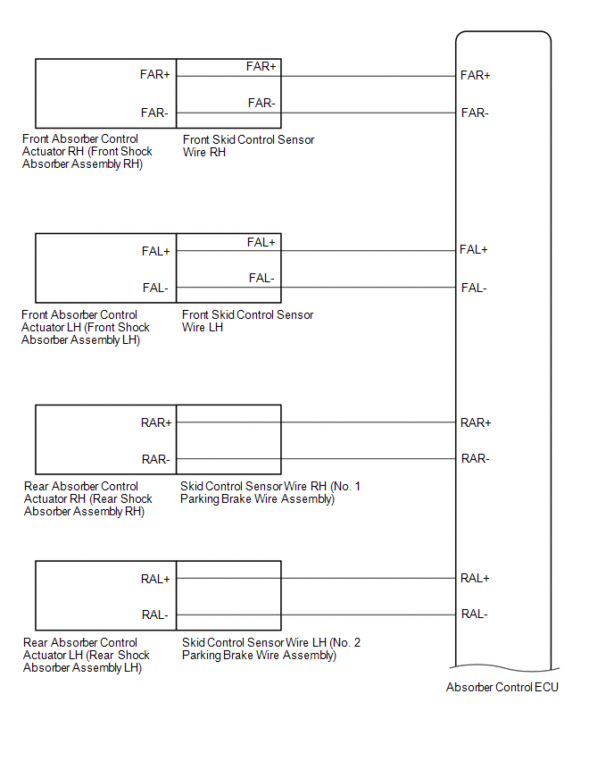
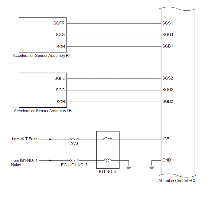
WIRING DIAGRAM
CAUTION / NOTICE / HINT
NOTICE:
Click here 
Click here
Click here
Click here
Click here
PROCEDURE
|
1. | READ VALUE USING TECHSTREAM ((UP & DOWN) G SENSOR) |
(a) Turn the engine switch off.
(b) Connect the Techstream to the DLC3.
(c) Turn the engine switch on (IG).
(d) Turn the Techstream on.
(e) Enter the following menus: Chassis / Air suspension / Data List.
Chassis > Air suspension > Data List|
Tester Display | Measurement Item |
Range | Normal Condition |
Diagnostic Note |
|---|---|---|---|---|
|
(Up&Down)G Sensor FR |
Front acceleration sensor RH (up and down) |
Min.: -1045.29 m/s2 Max.: 1045.26 m/s2 |
-0.98 to 0.98 m/s2 when stationary |
The value changes when the vehicle (front RH) is bounced. |
|
(Up&Down)G Sensor FL |
Front acceleration sensor LH (up and down) |
Min.: -1045.29 m/s2 Max.: 1045.26 m/s2 |
-0.98 to 0.98 m/s2 when stationary |
The value changes when the vehicle (front LH) is bounced. |
|
(Up&Down)G Sensor Rear |
Rear acceleration sensor (up and down) |
Min.: -1045.29 m/s2 Max.: 1045.26 m/s2 |
-0.98 to 0.98 m/s2 when stationary |
The value changes when the vehicle (rear) is bounced. |
|
Tester Display |
|---|
| (Up&Down)G Sensor FR |
|
(Up&Down)G Sensor FL |
|
(Up&Down)G Sensor Rear |
OK:
The values are as specified in the normal condition column.
| Result |
Proceed to |
|---|---|
| OK |
A |
| NG (front RH or front LH) |
B |
| NG (rear) |
C |
| B |
 | GO TO STEP 3 |
| C |
| REPLACE ABSORBER CONTROL ECU |
|
| 2. |
CHECK FOR DTCS |
(a) Clear the DTCs.
Click here
(b) Turn the engine switch off.
(c) Check for DTCs.
Click here
| Result |
Proceed to |
|---|---|
| DTCs are output (front RH or front LH) |
A |
| DTCs are output (rear) |
B |
| DTCs are not output |
C |
| B |
| REPLACE ABSORBER CONTROL ECU |
| C |
| USE SIMULATION METHOD TO CHECK |
|
| 3. |
INSPECT ACCELERATION SENSOR ASSEMBLY |
(a) Turn the engine switch off.
(b) Remove the acceleration sensor assembly RH or acceleration sensor assembly LH.
Click here
(c) Inspect the acceleration sensor assembly RH or acceleration sensor assembly LH.
Click here
| Result |
Proceed to |
|---|---|
| OK |
A |
| NG (Acceleration sensor assembly RH malfunction) |
B |
| NG (Acceleration sensor assembly LH malfunction) |
C |
| B |
| REPLACE ACCELERATION SENSOR ASSEMBLY RH |
| C |
| REPLACE ACCELERATION SENSOR ASSEMBLY LH |
|
| 4. |
CHECK HARNESS AND CONNECTOR (ACCELERATION SENSOR ASSEMBLY - ABSORBER CONTROL ECU) |
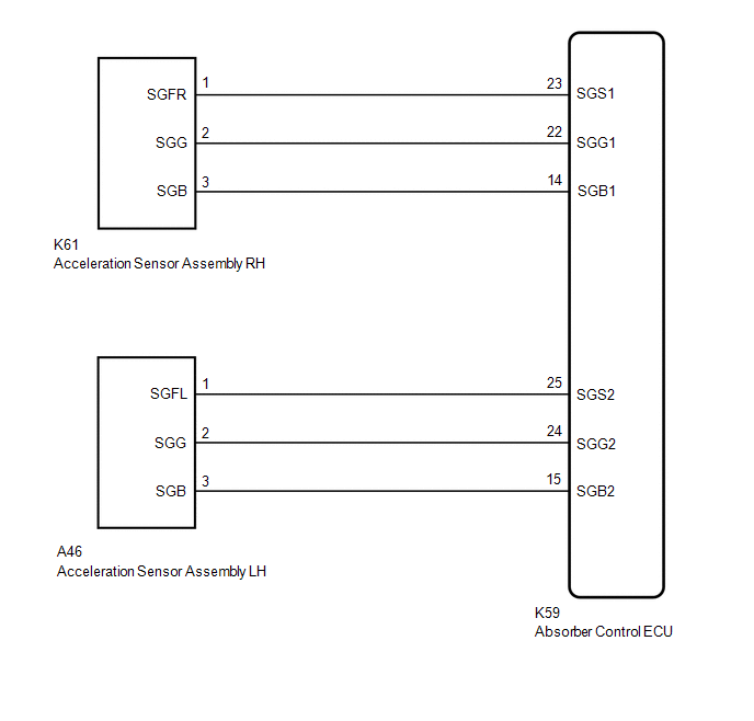
(a) Check the acceleration sensor assembly RH harness and connector (when DTC C1715 is output).
(1) Disconnect the K59 absorber control ECU connector.
(2) Disconnect the K61 acceleration sensor assembly RH connector.
(3) Measure the resistance according to the value(s) in the table below.
Standard Resistance:
|
Tester Connection | Condition |
Specified Condition |
|---|---|---|
|
K61-1 (SGFR) - K59-23 (SGS1) |
Always | Below 1 Ω |
|
K61-2 (SGG) - K59-22 (SGG1) |
Always | Below 1 Ω |
|
K61-3 (SGB) - K59-14 (SGB1) |
Always | Below 1 Ω |
|
K61-1 (SGFR) or K59-23 (SGS1) - Body ground |
Always | 10 kΩ or higher |
|
K61-2 (SGG) or K59-22 (SGG1) - Body ground |
Always | 10 kΩ or higher |
|
K61-3 (SGB) or K59-14 (SGB1) - Body ground |
Always | 10 kΩ or higher |
(b) Check the acceleration sensor assembly LH harness and connector (when DTC C1716 is output).
(1) Disconnect the K59 absorber control ECU connector.
(2) Disconnect the A46 acceleration sensor assembly LH connector.
(3) Measure the resistance according to the value(s) in the table below.
Standard Resistance:
|
Tester Connection | Condition |
Specified Condition |
|---|---|---|
|
A46-1 (SGFL) - K59-25 (SGS2) |
Always | Below 1 Ω |
|
A46-2 (SGG) - K59-24 (SGG2) |
Always | Below 1 Ω |
|
A46-3 (SGB) - K59-15 (SGB2) |
Always | Below 1 Ω |
|
A46-1 (SGFL) or K59-25 (SGS2) - Body ground |
Always | 10 kΩ or higher |
|
A46-2 (SGG) or K59-24 (SGG2) - Body ground |
Always | 10 kΩ or higher |
|
A46-3 (SGB) or K59-15 (SGB2) - Body ground |
Always | 10 kΩ or higher |
| OK | | REPLACE ABSORBER CONTROL ECU |
| NG | | REPAIR OR REPLACE HARNESS OR CONNECTOR |
DESCRIPTION
The absorber control actuator changes the damping force depending on absorber control ECU signals.
|
DTC No. | Detection Item |
DTC Detection Condition | Trouble Area |
Warning Indicate | Memory |
|---|---|---|---|---|---|
|
C1731 | FR Damping Force Control Actuator Circuit |
Either condition is met:
|
| Does not come on |
Yes |
| C1732 |
FL Damping Force Control Actuator Circuit |
Either condition is met:
|
| Does not come on |
Yes |
| C1733 |
RR Damping Force Control Actuator Circuit |
Either condition is met:
|
| Does not come on |
Yes |
| C1734 |
RL Damping Force Control Actuator Circuit |
Either condition is met:
|
| Does not come on |
Yes |
WIRING DIAGRAM
CAUTION / NOTICE / HINT
NOTICE:
Click here 
Click here
Click here
Click here
Click here
PROCEDURE
|
1. | CLEAR DTCS |
(a) Clear the DTCs.
Click here
|
| 2. |
PERFORM ACTIVE TEST USING TECHSTREAM (FOUR-WHEEL DAMPING FORCE FULL HARD/SOFT) |
(a) Turn the engine switch off.
(b) Connect the Techstream to the DLC3.
(c) Start the engine.
(d) Turn the Techstream on.
(e) Enter the following menus: Chassis / Air suspension /Active Test.
Chassis > Air suspension > Active Test|
Tester Display | Measurement Item |
Restrict Condition |
|---|---|---|
|
Four-Wheel Damping Force Full Hard |
Four-wheel damper step fixed at full hard |
|
| Four-Wheel Damping Force Full Soft |
Four-wheel damper step fixed at full soft |
|
|
Tester Display |
|---|
| Four-Wheel Damping Force Full Hard |
|
Tester Display |
|---|
| Four-Wheel Damping Force Full Soft |
(f) When performing the Active Test, read each Tester Display item for the applicable wheel on the Data List and check the operation status of the absorber control actuator for the applicable wheel.
Chassis > Air suspension > Data List|
Tester Display | Measurement Item |
Range | Normal Condition |
Diagnostic Note |
|---|---|---|---|---|
|
FR Solenoid Aim Electric Current Level for Control |
Target solenoid current value (front wheel RH) |
Min.: 0 mA Max.: 2040 mA |
Changes depending on target damping force |
- |
| FL Solenoid Aim Electric Current Level for Control |
Target solenoid current value (front wheel LH) |
Min.: 0 mA Max.: 2040 mA |
Changes depending on target damping force |
- |
| RR Solenoid Aim Electric Current Level for Control |
Target solenoid current value (rear wheel RH) |
Min.: 0 mA Max.: 2040 mA |
Changes depending on target damping force |
- |
| RL Solenoid Aim Electric Current Level for Control |
Target solenoid current value (rear wheel LH) |
Min.: 0 mA Max.: 2040 mA |
Changes depending on target damping force |
- |
| FR Solenoid Drive Duty |
Solenoid drive duty value (front wheel RH) |
Min.: 0% Max.: 100% |
Changes depending on target damping force |
- |
| FL Solenoid Drive Duty |
Solenoid drive duty value (front wheel LH) |
Min.: 0% Max.: 100% |
Changes depending on target damping force |
- |
| RR Solenoid Drive Duty |
Solenoid drive duty value (rear wheel RH) |
Min.: 0% Max.: 100% |
Changes depending on target damping force |
- |
| RL Solenoid Drive Duty |
Solenoid drive duty value (rear wheel LH) |
Min.: 0% Max.: 100% |
Changes depending on target damping force |
- |
| FR Solenoid Electric Current |
Solenoid current value (front wheel RH) |
Min.: 0 mA Max.: 2040 mA |
Changes depending on target damping force |
- |
| FL Solenoid Electric Current |
Solenoid current value (front wheel LH) |
Min.: 0 mA Max.: 2040 mA |
Changes depending on target damping force |
- |
| RR Solenoid Electric Current |
Solenoid current value (rear wheel RH) |
Min.: 0 mA Max.: 2040 mA |
Changes depending on target damping force |
- |
| RL Solenoid Electric Current |
Solenoid current value (rear wheel LH) |
Min.: 0 mA Max.: 2040 mA |
Changes depending on target damping force |
- |
|
Tester Display |
|---|
| FR Solenoid Aim Electric Current Level for Control |
|
FL Solenoid Aim Electric Current Level for Control |
|
RR Solenoid Aim Electric Current Level for Control |
|
RL Solenoid Aim Electric Current Level for Control |
|
FR Solenoid Drive Duty |
|
FL Solenoid Drive Duty |
|
RR Solenoid Drive Duty |
|
RL Solenoid Drive Duty |
|
FR Solenoid Electric Current |
|
FL Solenoid Electric Current |
|
RR Solenoid Electric Current |
|
RL Solenoid Electric Current |
OK:
The Data List step numbers, drive duty values and current values change according to the operation of the Active Test.
| NG |  | GO TO STEP 4 |
|
| 3. |
RECONFIRM DTC |
(a) Check that the same DTC is output.
Click here
| Result |
Proceed to |
|---|---|
| DTC is output |
A |
| DTC is not output |
B |
| B |
| USE SIMULATION METHOD TO CHECK |
|
| 4. |
INSPECT ABSORBER CONTROL ACTUATOR (SHOCK ABSORBER ASSEMBLY) |
(a) Turn the engine switch off.
(b) Inspect the absorber control actuator (shock absorber assembly).
for Front Side: Click here
for Rear Side: Click here
|
Result | Proceed to |
|---|---|
|
OK (for Front Side) | A |
|
OK (for Rear Side) | B |
|
NG (Front absorber control actuator RH (front shock absorber assembly RH) malfunction) |
C |
| NG (Front absorber control actuator LH (front shock absorber assembly LH) malfunction) |
D |
| NG (Rear absorber control actuator RH (rear shock absorber assembly RH) malfunction) |
E |
| NG (Rear absorber control actuator LH (rear shock absorber assembly LH) malfunction) |
F |
| B |
| GO TO STEP 7 |
| C |
| REPLACE FRONT ABSORBER CONTROL ACTUATOR RH (FRONT SHOCK ABSORBER ASSEMBLY RH) |
| D |
| REPLACE FRONT ABSORBER CONTROL ACTUATOR LH (FRONT SHOCK ABSORBER ASSEMBLY LH) |
| E |
| REPLACE REAR ABSORBER CONTROL ACTUATOR RH (REAR SHOCK ABSORBER ASSEMBLY RH) |
| F |
| REPLACE REAR ABSORBER CONTROL ACTUATOR LH (REAR SHOCK ABSORBER ASSEMBLY LH) |
|
| 5. |
INSPECT FRONT SKID CONTROL SENSOR WIRE |
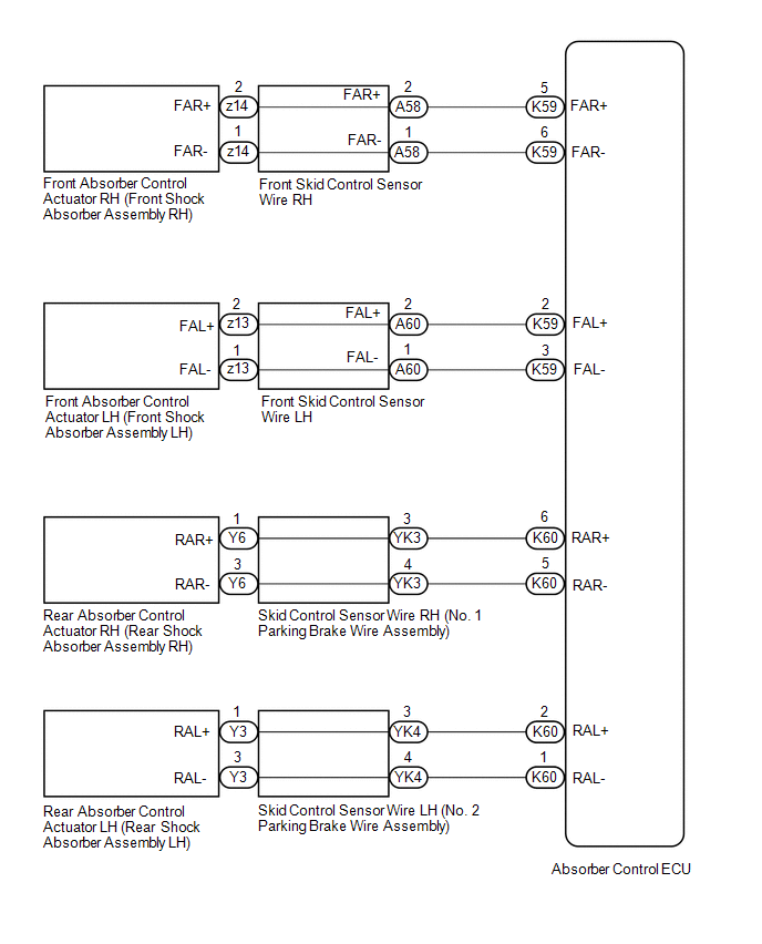
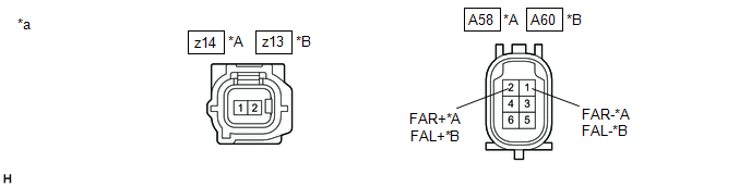
(a) Disconnect the z14 or z13 front skid control sensor wire connector.
(b) Disconnect the A58 or A60 front skid control sensor wire connector.
(c) Measure the resistance according to the value(s) in the table below.
|
*A | for RH |
*B | for LH |
|
*a | Component without harness connected (Front Skid Control Sensor Wire) |
- | - |
Standard Resistance:
for RH|
Tester Connection | Condition |
Specified Condition |
|---|---|---|
|
z14-2 - A58-2 (FAR+) |
Always | Below 1 Ω |
|
z14-1 - A58-1 (FAR-) | ||
| z14-2 or A58-2 (FAR+) - Body ground and other terminals |
Always | 10 kΩ or higher |
|
z14-1 or A58-1 (FAR-) - Body ground and other terminals |
|
Tester Connection | Condition |
Specified Condition |
|---|---|---|
|
z13-2 - A60-2 (FAL+) |
Always | Below 1 Ω |
|
z13-1 - A60-1 (FAL-) | ||
|
z13-2 or A60-2 (FAL+) - Body ground and other terminals |
Always | 10 kΩ or higher |
|
z13-1 or A60-1 (FAL-) - Body ground and other terminals |
|
Result | Proceed to |
|---|---|
|
OK | A |
|
NG (for RH) | B |
|
NG (for LH) | C |
| B |
| REPLACE FRONT SKID CONTROL SENSOR WIRE RH |
| C |
| REPLACE FRONT SKID CONTROL SENSOR WIRE LH |
|
| 6. |
CHECK HARNESS AND CONNECTOR (FRONT SKID CONTROL SENSOR WIRE - ABSORBER CONTROL ECU) |
(a) Disconnect the K59 absorber control ECU connector.
(b) Measure the resistance according to the value(s) in the table below.
Standard Resistance:
for RH|
Tester Connection | Condition |
Specified Condition |
|---|---|---|
|
A58-2 (FAR+) - K59-5 (FAR+) |
Always | Below 1 Ω |
|
A58-1 (FAR-) - K59-6 (FAR-) | ||
|
A58-2 (FAR+) or K59-5 (FAR+) - Body ground and other terminals |
Always | 10 kΩ or higher |
|
A58-1 (FAR-) or K59-6 (FAR-) - Body ground and other terminals |
|
Tester Connection | Condition |
Specified Condition |
|---|---|---|
|
A60-2 (FAL+) - K59-2 (FAL+) |
Always | Below 1 Ω |
|
A60-1 (FAL-) - K59-3 (FAL-) | ||
|
A60-2 (FAL+) or K59-2 (FAL+) - Body ground and other terminals |
Always | 10 kΩ or higher |
|
A60-1 (FAL-) or K59-3 (FAL-) - Body ground and other terminals |
| OK | | REPLACE ABSORBER CONTROL ECU |
| NG | | REPAIR OR REPLACE HARNESS OR CONNECTOR |
| 7. |
INSPECT SKID CONTROL SENSOR WIRE (PARKING BRAKE WIRE ASSEMBLY) |
(a) Disconnect the Y6 or Y3 skid control sensor wire (parking brake wire assembly) connector.
(b) Disconnect the YK3 or YK4 skid control sensor wire (parking brake wire assembly) connector.
(c) Measure the resistance according to the value(s) in the table below.

|
*A | for RH |
*B | for LH |
|
*a | Component without harness connected (Skid Control Sensor Wire (Parking Brake Wire Assembly)) |
- | - |
Standard Resistance:
for RH|
Tester Connection | Condition |
Specified Condition |
|---|---|---|
|
Y6-1 - YK3-3 |
Always | Below 1 Ω |
|
Y6-3 - YK3-4 | ||
| Y6-1 or YK3-3 - Body ground and other terminals |
Always | 10 kΩ or higher |
|
Y6-3 or YK3-4 - Body ground and other terminals |
|
Tester Connection | Condition |
Specified Condition |
|---|---|---|
|
Y3-1 - YK4-3 |
Always | Below 1 Ω |
|
Y3-3 - YK4-4 | ||
|
Y3-1 or YK4-3 - Body ground and other terminals |
Always | 10 kΩ or higher |
|
Y3-3 or YK4-4 - Body ground and other terminals |
|
Result | Proceed to |
|---|---|
|
OK | A |
|
NG (for RH) | B |
|
NG (for LH) | C |
| B |
| REPLACE SKID CONTROL SENSOR WIRE RH (NO. 1 PARKING BRAKE WIRE ASSEMBLY) |
| C |
| REPLACE SKID CONTROL SENSOR WIRE LH (NO. 2 PARKING BRAKE WIRE ASSEMBLY) |
|
| 8. |
CHECK HARNESS AND CONNECTOR (SKID CONTROL SENSOR WIRE (PARKING BRAKE WIRE ASSEMBLY) - ABSORBER CONTROL ECU) |
(a) Disconnect the K60 absorber control ECU connector.
(b) Measure the resistance according to the value(s) in the table below.
Standard Resistance:
for RH|
Tester Connection | Condition |
Specified Condition |
|---|---|---|
|
YK3-3 - K60-6 (RAR+) |
Always | Below 1 Ω |
|
YK3-4 - K60-5 (RAR-) | ||
|
YK3-3 or K60-6 (RAR+) - Body ground and other terminals |
Always | 10 kΩ or higher |
|
YK3-4 or K60-5 (RAR-) - Body ground and other terminals |
|
Tester Connection | Condition |
Specified Condition |
|---|---|---|
|
YK4-3 - K60-2 (RAL+) |
Always | Below 1 Ω |
|
YK4-4 - K60-1 (RAL-) | ||
|
YK4-3 or K60-2 (RAL+) - Body ground and other terminals |
Always | 10 kΩ or higher |
|
YK4-4 or K60-1 (RAL-) - Body ground and other terminals |
| OK | | REPLACE ABSORBER CONTROL ECU |
| NG | | REPAIR OR REPLACE HARNESS OR CONNECTOR |
DESCRIPTION
If a malfunction in the absorber control ECU is detected, DTC C1781 is stored.
|
DTC No. | Detection Item |
DTC Detection Condition | Trouble Area |
Warning Indicate | Memory |
|---|---|---|---|---|---|
|
C1781 | Suspension Control ECU Malfunction |
One of the following conditions is met:
|
| Does not come on |
Yes |
CAUTION / NOTICE / HINT
NOTICE:
Click here 
Click here
Click here
Click here
Click here
PROCEDURE
|
1. | CHECK FOR DTCS (CAN COMMUNICATION SYSTEM) |
(a) Check for DTCs.
Click here
| Result |
Proceed to |
|---|---|
| CAN DTCs are not output |
A |
| CAN DTCs are output |
B |
| A |
 | REPLACE ABSORBER CONTROL ECU |
| B |
| GO TO CAN COMMUNICATION SYSTEM (HOW TO PROCEED WITH TROUBLESHOOTING) |
DESCRIPTION
This DTC (C1782) is output if voltage matching the DTC detection condition continues to be supplied to the IGB terminal of the absorber control ECU due to malfunctions in the power source or charging circuits, such as the battery or generator assembly circuits.
|
DTC No. | Detection Item |
DTC Detection Condition | Trouble Area |
Warning Indicate | Memory |
|---|---|---|---|---|---|
|
C1782 | Low Battery Positive Voltage |
While the engine switch is on (IG), the voltage at terminal IGB is 10 V or less, or 16 V or more for 0.5 seconds. |
| Does not come on |
No |
WIRING DIAGRAM
CAUTION / NOTICE / HINT
NOTICE:
Click here 
Click here
Click here
Click here
PROCEDURE
|
1. | READ VALUE USING TECHSTREAM (IG POWER SOURCE VOLTAGE) |
(a) Turn the engine switch off.
(b) Connect the Techstream to the DLC3.
(c) Turn the engine switch on (IG).
(d) Turn the Techstream on.
(e) Enter the following menus: Chassis / Air suspension / Data List.
Chassis > Air suspension > Data List|
Tester Display | Measurement Item |
Range | Normal Condition |
Diagnostic Note |
|---|---|---|---|---|
|
IG Power Source Voltage |
ECU power supply voltage |
Min.: 0.0 V Max.: 25.5 V |
11 to 14 V (Actual ECU power supply voltage): Engine switch on (IG) |
- |
|
Tester Display |
|---|
| IG Power Source Voltage |
OK:
The value is as specified in the normal condition column.
| NG |  | GO TO STEP 3 |
|
| 2. |
CHECK FOR DTCS |
(a) Clear the DTCs.
Click here
(b) Turn the engine switch off.
(c) Check for DTCs.
Click here
|
Result | Proceed to |
|---|---|
|
DTC is not output | A |
|
DTC is output | B |
| A |
| USE SIMULATION METHOD TO CHECK |
| B |
| REPLACE ABSORBER CONTROL ECU |
| 3. |
INSPECT BATTERY |
(a) Check the battery voltage.
Standard Voltage:
11 to 14 V
| NG | | CHECK OR REPLACE CHARGING SYSTEM OR BATTERY |
|
| 4. |
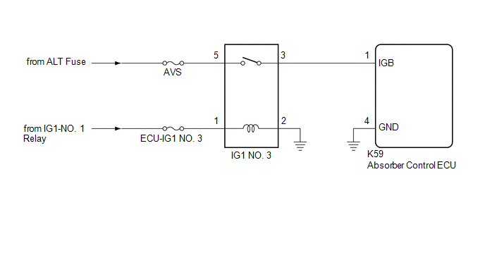
INSPECT IG1 NO. 3 RELAY |
(a) Turn the engine switch off.
(b) Inspect the IG1 NO. 3 relay.
Click here
| NG | |
REPLACE IG1 NO. 3 RELAY |
|
| 5. |
CHECK HARNESS AND CONNECTOR (POWER SOURCE - IG1 NO. 3 RELAY) |
(a) Measure the voltage according to the value(s) in the table below.
Standard Voltage:
|
Tester Connection | Condition |
Specified Condition |
|---|---|---|
|
1 (IG1 NO. 3 relay) - Body ground |
Engine switch on (IG) |
11 to 14 V |
|
5 (IG1 NO. 3 relay) - Body ground |
Always | 11 to 14 V |
| NG | | CHECK OR REPLACE CHARGING SYSTEM OR BATTERY |
|
| 6. |
CHECK HARNESS AND CONNECTOR (IG1 NO. 3 RELAY - ABSORBER CONTROL ECU AND BODY GROUND) |
(a) Disconnect the K59 absorber control ECU connector.
(b) Measure the resistance according to the value(s) in the table below.
Standard Resistance:
|
Tester Connection | Condition |
Specified Condition |
|---|---|---|
|
3 (IG1 NO. 3 relay) - K59-1 (IGB) |
Always | Below 1 Ω |
|
3 (IG1 NO. 3 relay) or K59-1 (IGB) - Body ground |
Always | 10 kΩ or higher |
|
2 (IG1 NO. 3 relay) - Body ground |
Always | Below 1 Ω |
| NG | | REPAIR OR REPLACE HARNESS OR CONNECTOR |
|
| 7. |
CHECK HARNESS AND CONNECTOR (ABSORBER CONTROL ECU - BODY GROUND) |
(a) Measure the resistance according to the value(s) in the table below.
Standard Resistance:
|
Tester Connection | Condition |
Specified Condition |
|---|---|---|
|
K59-4 (GND) - Body ground |
Always | Below 1 Ω |
| OK | | REPLACE ABSORBER CONTROL ECU |
| NG | | REPAIR OR REPLACE HARNESS OR CONNECTOR |
DESCRIPTION
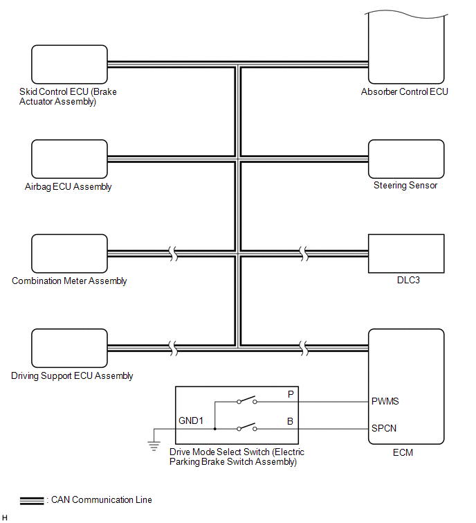
The speed sensors monitor the speed of the wheels and send an appropriate speed signal to the absorber control ECU through the skid control ECU (brake actuator assembly).
If a malfunction occurs in either a front speed sensor or rear speed sensor, DTC C1783 is stored.
|
DTC No. | Detection Item |
DTC Detection Condition | Trouble Area |
Warning Indicate | Memory |
|---|---|---|---|---|---|
|
C1783 | Front Wheels Speed Sensor Signal Malfunction |
A speed sensor malfunction signal from the skid control ECU (brake actuator assembly) is detected for 1 second or more. |
Electronically controlled brake system |
Does not come on | Yes |
PROCEDURE
| 1. |
GO TO ELECTRONICALLY CONTROLLED BRAKE SYSTEM |
(a) Go to electronically controlled brake system.
Click here

| NEXT |  |
END |
DESCRIPTION
Steering sensor signals are sent to the absorber control ECU via CAN communication.
If a communication error is detected, DTC C1784 is stored.
|
DTC No. | Detection Item |
DTC Detection Condition | Trouble Area |
Warning Indicate | Memory |
|---|---|---|---|---|---|
|
C1784 | Steering Sensor Signal Malfunction |
A steering sensor communication error is detected, or a steering sensor power malfunction is detected for 5 seconds or more. |
Electronically controlled brake system |
Does not come on | Yes (Under some of the detection conditions (sensor power +B open malfunction is detected), DTC is not stored.) |
PROCEDURE
| 1. |
GO TO ELECTRONICALLY CONTROLLED BRAKE SYSTEM |
(a) Go to electronically controlled brake system.
Click here

| NEXT |  |
END |
DESCRIPTION
The absorber control ECU stores this DTC when a malfunction signal from the master cylinder pressure sensor built into the brake actuator assembly is received via CAN communication.
|
DTC No. | Detection Item |
DTC Detection Condition | Trouble Area |
Warning Indicate | Memory |
|---|---|---|---|---|---|
|
C1786 | Master Cylinder Pressure Circuit |
A master cylinder pressure sensor malfunction signal is continuously received from the skid control ECU (brake actuator assembly) for 3 seconds or more. | Electronically controlled brake system |
Does not come on | Yes |
PROCEDURE
| 1. |
GO TO ELECTRONICALLY CONTROLLED BRAKE SYSTEM |
(a) Go to electronically controlled brake system.
Click here

| NEXT |  |
END |
DESCRIPTION
The absorber control ECU receives a signal from the yaw rate and acceleration sensor (airbag ECU assembly) via CAN communication.
|
DTC No. | Detection Item |
DTC Detection Condition | Trouble Area |
Warning Indicate | Memory |
|---|---|---|---|---|---|
|
C1787 | (Horizontality) G Sensor Malfunction |
While the engine switch is on (IG), yaw rate and acceleration sensor (airbag ECU assembly) malfunction signal is detected for 1 second or more. |
Electronically controlled brake system |
Does not come on | Yes |
PROCEDURE
| 1. |
GO TO ELECTRONICALLY CONTROLLED BRAKE SYSTEM |
(a) Go to electronically controlled brake system.
Click here

| NEXT |  |
END |
DESCRIPTION
When the absorber control ECU has not acquired the vehicle identification information, DTC C1789 is stored. When the vehicle identification information is correctly acquired, this DTC is cleared. Vehicle identification information is automatically acquired when the system enters test mode.
If an incorrect ECM is installed, the vehicle information will not match and DTC C1789 will be stored.
|
DTC No. | Detection Item |
DTC Detection Condition | Trouble Area |
Warning Indicate | Memory |
|---|---|---|---|---|---|
|
C1789 | Vehicle Identification Malfunction |
One of the following conditions is met:
|
| Does not come on |
Yes (Under some of the detection conditions (control map non-retrieval is not stored), DTC is not stored.) |
CAUTION / NOTICE / HINT
NOTICE:
Click here 
Click here
Click here
Click here
Click here
PROCEDURE
|
1. | CHECK FOR DTCS |
(a) Check for DTCs.
Click here
HINT:
If DTC C1781 (Suspension Control ECU Malfunction) is output at the same time, perform troubleshooting for C1781 first.
|
Result | Proceed to |
|---|---|
|
C1781 and CAN communication malfunction DTC are not output |
A |
| C1781 is output |
B |
| CAN communication DTC is output |
C |
| B |
 | GO TO C1781 |
| C |
| GO TO CAN COMMUNICATION SYSTEM (HOW TO PROCEED WITH TROUBLESHOOTING) |
|
| 2. |
CHECK VEHICLE IDENTIFICATION INFORMATION STATUS |
(a) Check that vehicle identification information has been stored.
Click here
|
Result | Proceed to |
|---|---|
|
Information stored | A |
|
Information not stored |
B |
| B |
| PERFORM VEHICLE IDENTIFICATION INFORMATION REGISTRATION |
|
| 3. |
CHECK RELATED PART |
(a) If the DTC was output as a result of the replacement of a related part, replace the part with one that has a correct part number.
|
Related Part | ECM |
NOTICE:
When removing a related part to check it, be sure to follow the appropriate procedures and precautions.
Refer to the following procedures to remove the ECM.
Click here
HINT:
If parts have not been replaced and DTC C1789 is output, there may be an internal malfunction in the absorber control ECU. Therefore, replace the absorber control ECU.
|
Result | Proceed to |
|---|---|
|
The related part has an incorrect part number |
A |
| The related part has the correct part number, or a related part and absorber control ECU have not been replaced |
B |
| A |
| REPLACE RELATED PART WITH PART THAT HAS CORRECT PART NUMBER |
| B |
| REPLACE ABSORBER CONTROL ECU |
CUSTOMIZE PARAMETERS
CUSTOMIZE ADAPTIVE VARIABLE SUSPENSION SYSTEM
HINT:
"Custom" mode can be selected by using the drive mode select switch (electric parking brake switch assembly).
(a) Customizing with the multi-display
(1) Turn the engine switch on (IG).
(2) Enter the following menus: MENU / Setup / Vehicle / Vehicle Customization / Drive Mode Customization.
(3) Select the setting by referring to the table below.
|
Display | Content |
Default | Setting |
|---|---|---|---|
|
Powertrain | Acceleration response, etc. |
Normal | Power / Normal / Eco |
|
Chassis | Damping force of suspension, steering assist force, etc. |
Normal | Sport / Normal |
|
Climate | Effectiveness of air conditioning system, etc. |
Normal | Normal / Eco |
DATA LIST / ACTIVE TEST
READ DATA LIST
NOTICE:
In the table below, the values listed under "Normal Condition" are reference values. Do not depend solely on these reference values when deciding whether a part is faulty or not.
HINT:
Using the Techstream to read the Data List allows the values or states of switches, sensors, actuators and other items to be read without removing any parts. This non-intrusive inspection can be very useful because intermittent conditions or signals may be discovered before parts or wiring is disturbed. Reading the Data List information early in troubleshooting is one way to save diagnostic time.
(a) Turn the engine switch off.
(b) Connect the Techstream to the DLC3.
(c) Turn the engine switch on (IG).
(d) Turn the Techstream on.
(e) Enter the following menus: Chassis / Air suspension / Data List.
(f) Read the Data List according to the display on the Techstream.
Chassis > Air suspension > Data List|
Tester Display | Measurement Item |
Range | Normal Condition |
Diagnostic Note |
|---|---|---|---|---|
|
(Up&Down)G Sensor FR |
Front acceleration sensor RH (up and down) |
Min.: -1045.29 m/s2 Max.: 1045.26 m/s2 |
-0.98 to 0.98 m/s2 when stationary |
The value changes when the vehicle (front RH) is bounced. |
|
(Up&Down)G Sensor FL |
Front acceleration sensor LH (up and down) |
Min.: -1045.29 m/s2 Max.: 1045.26 m/s2 |
-0.98 to 0.98 m/s2 when stationary |
The value changes when the vehicle (front LH) is bounced. |
|
(Up&Down)G Sensor Rear |
Rear acceleration sensor (up and down) |
Min.: -1045.29 m/s2 Max.: 1045.26 m/s2 |
-0.98 to 0.98 m/s2 when stationary |
The value changes when the vehicle (rear) is bounced. |
|
Gravity Sensor(Side to Side) |
Lateral acceleration sensor (side to side) |
Min.: -1176.37 m/s2 Max.: 1176.33 m/s2 |
Changes depending on acceleration generated when turning |
- |
| Stop Light Switch |
Stop light switch | OFF or ON |
OFF: Brake pedal released ON: Brake pedal depressed |
- |
| SPORT Switch |
Drive mode select switch |
OFF or ON | OFF: Not in Sport S+ mode or Custom mode (when the Chassis item is set to SPORT) ON: During Sport S+ mode or Custom mode (when the Chassis item is set to SPORT) |
- |
| HV Ready |
HV ready status | OFF or ON |
OFF: Always | This item is displayed on the Techstream but is not required for diagnosis or repair. |
|
TC Terminal | TC terminal status |
OFF or ON | OFF: DTC not output ON: DTC output | - |
|
TS Terminal | TS terminal status |
OFF or ON | OFF: During normal mode ON: During test mode |
- |
| IG Power Source Voltage |
ECU power supply voltage |
Min.: 0.0 V Max.: 25.5 V |
11 to 14 V (Actual ECU power supply voltage): Engine switch on (IG) |
- |
| Steering Angle |
Steering angle sensor reading |
Min.: -49152.0 deg Max.: 49150.5 deg |
Actual steering angle Steering wheel turned left: Reading increases Steering wheel turned right: Reading decreases |
- |
| Engine Speed |
Engine speed | Min.: 0 rpm Max.: 25500 rpm | Actual engine speed |
- |
| FR Wheel Speed |
Front speed sensor RH reading |
Min.: 0 km/h (0 mph) Max.: 255 km/h (159 mph) |
Actual vehicle speed | No large fluctuations when driving at a constant speed. |
|
FL Wheel Speed | Front speed sensor LH reading |
Min.: 0 km/h (0 mph) Max.: 255 km/h (159 mph) |
Actual vehicle speed | No large fluctuations when driving at a constant speed. |
|
RR Wheel Speed | Rear speed sensor RH reading |
Min.: 0 km/h (0 mph) Max.: 255 km/h (159 mph) |
Actual vehicle speed | No large fluctuations when driving at a constant speed. |
|
RL Wheel Speed | Rear speed sensor LH reading |
Min.: 0 km/h (0 mph) Max.: 255 km/h (159 mph) |
Actual vehicle speed | No large fluctuations when driving at a constant speed. |
|
Driving Torque | Driving torque |
Min.: -1024 Nm Max.: 1023 Nm |
Changes in accordance with accelerator pedal position |
- |
| Adaptive Variable Suspension(AVS) Mode |
Adaptive variable suspension system (AVS) mode |
NORMAL, COMFORT, SEMI CO, SEMI SP or SPORTS |
NORMAL: Not in Sport S+ mode or Custom mode (when the Chassis item is set to SPORT) SPORTS: During Sport S+ mode or Custom mode (when the Chassis item is set to SPORT) |
- |
| Compatible Constant Information |
Information used to change the compatible constant |
Min.: 0 Max.: 255 |
- | - |
|
Identical Constant Information |
Information used to change the identical constant |
Min.: 0 Max.: 255 |
- | - |
|
Design Constant Information |
Information used to change the design constant |
Min.: 0 Max.: 255 |
- | - |
|
AVS Control Information FR |
AVS control information (front wheel RH) |
Min.: 0 Max.: 255 |
- | - |
|
AVS Control Information FL |
AVS control information (front wheel LH) |
Min.: 0 Max.: 255 |
- | - |
|
AVS Control Information RR |
AVS control information (rear wheel RH) |
Min.: 0 Max.: 255 |
- | - |
|
AVS Control Information RL |
AVS control information (rear wheel LH) |
Min.: 0 Max.: 255 |
- | - |
|
Vehicle Information (Conv/HV) |
Vehicle identification information (hybrid vehicle or except hybrid vehicle) |
Unknown, Conv or HV | Conv: When vehicle identification normal |
- |
| Stop and Start Learning Status |
Learning status of stop and start setting availability after vehicle identification information registration is performed |
Unset, OFF or ON | OFF |
- |
| Overheat Protection Control Count |
Number of times overheat protection was performed in past |
Min.: 0 Max.: 255 |
Displays number of times overheat protection was performed in past |
- |
| ECU Substrate Maximum Temperature |
Stored ECU substrate maximum temperature |
Min.: 40°C Max.: 120°C |
Displays maximum temperature of ECU substrate in past |
- |
| Status of Overheat Protection Control |
Current overheat protection status |
OFF or ON | OFF: No overheat protection |
ON: When overheat protection is on, damping force control stops until the temperature drops below a certain value. |
|
G Sensor Voltage | G sensor power supply voltage |
Min.: 0.0 V Max.: 25.5 V |
4.8 to 5.2 V | - |
|
ECU Substrate Temperature |
Current ECU substrate temperature |
Min.: 40°C Max.: 120°C |
Displays current ECU substrate temperature |
- |
| FR Solenoid Aim Electric Current Level for Control |
Target solenoid current value (front wheel RH) |
Min.: 0 mA Max.: 2040 mA |
Changes depending on target damping force |
- |
| FL Solenoid Aim Electric Current Level for Control |
Target solenoid current value (front wheel LH) |
Min.: 0 mA Max.: 2040 mA |
Changes depending on target damping force |
- |
| RR Solenoid Aim Electric Current Level for Control |
Target solenoid current value (rear wheel RH) |
Min.: 0 mA Max.: 2040 mA |
Changes depending on target damping force |
- |
| RL Solenoid Aim Electric Current Level for Control |
Target solenoid current value (rear wheel LH) |
Min.: 0 mA Max.: 2040 mA |
Changes depending on target damping force |
- |
| FR Solenoid Drive Duty |
Solenoid drive duty value (front wheel RH) |
Min.: 0% Max.: 100% |
Changes depending on target damping force |
- |
| FL Solenoid Drive Duty |
Solenoid drive duty value (front wheel LH) |
Min.: 0% Max.: 100% |
Changes depending on target damping force |
- |
| RR Solenoid Drive Duty |
Solenoid drive duty value (rear wheel RH) |
Min.: 0% Max.: 100% |
Changes depending on target damping force |
- |
| RL Solenoid Drive Duty |
Solenoid drive duty value (rear wheel LH) |
Min.: 0% Max.: 100% |
Changes depending on target damping force |
- |
| FR Solenoid Electric Current |
Solenoid current value (front wheel RH) |
Min.: 0 mA Max.: 2040 mA |
Changes depending on target damping force |
- |
| FL Solenoid Electric Current |
Solenoid current value (front wheel LH) |
Min.: 0 mA Max.: 2040 mA |
Changes depending on target damping force |
- |
| RR Solenoid Electric Current |
Solenoid current value (rear wheel RH) |
Min.: 0 mA Max.: 2040 mA |
Changes depending on target damping force |
- |
| RL Solenoid Electric Current |
Solenoid current value (rear wheel LH) |
Min.: 0 mA Max.: 2040 mA |
Changes depending on target damping force |
- |
| Air suspension Learning Status |
Learning status of air suspension system setting availability after vehicle identification information registration is performed |
Unset, OFF or ON | OFF |
- |
| Number of Trouble Codes |
Number of DTCs stored | Min.: 0 Max.: 255 | 0 |
- |
PERFORM ACTIVE TEST
HINT:
Using the Techstream to perform Active Tests allows relays, VSVs, actuators and other items to be operated without removing any parts. This non-intrusive functional inspection can be very useful because intermittent operation may be discovered before parts or wiring is disturbed. Performing Active Tests early in troubleshooting is one way to save diagnosis time. Data List information can be displayed while performing Active Tests.
(a) Turn the engine switch off.
(b) Connect the Techstream to the DLC3.
(c) Start the engine.
(d) Turn the Techstream on.
(e) Enter the following menus: Chassis / Air suspension / Active Test.
(f) Perform the Active Test according to the display on the Techstream.
Chassis > Air suspension > Active Test|
Tester Display | Measurement Item |
Restrict Condition |
|---|---|---|
|
Four-Wheel Damping Force Full Hard |
Four-wheel damping force fixed at full hard |
|
| Four-Wheel Damping Force Full Soft |
Four-wheel damper step fixed at full soft |
|
| Damper Step FR (Electric Current) |
Changes damping force (front RH) |
|
| Damper Step FL (Electric Current) |
Changes damping force (front LH) |
|
| Damper Step RR (Electric Current) |
Changes damping force (rear RH) |
|
| Damper Step RL (Electric Current) |
Changes damping force (rear LH) |
|
DIAGNOSIS SYSTEM
DIAGNOSIS SYSTEM
(a) DTCs (normal mode)
(1) DTCs are stored in the absorber control ECU and output by using the Techstream. Refer to the DTC check procedure.
Click here 
(b) Test mode
(1) By switching from normal mode to test mode, it is possible to inspect the front acceleration sensor and rear acceleration sensor.
Click here
DIAGNOSTIC TROUBLE CODE CHART
Adaptive Variable Suspension System|
DTC No. | Detection Item |
Warning Indicate | Memory |
Link |
|---|---|---|---|---|
| C1715 |
Front Acceleration Sensor RH Malfunction |
Does not come on | Yes |
|
|
C1716 | Front Acceleration Sensor LH Malfunction |
Does not come on | Yes |
|
|
C1717 | Rear Acceleration Sensor Malfunction |
Does not come on | Yes |
|
|
C1731 | FR Damping Force Control Actuator Circuit |
Does not come on | Yes |
|
|
C1732 | FL Damping Force Control Actuator Circuit |
Does not come on | Yes |
|
|
C1733 | RR Damping Force Control Actuator Circuit |
Does not come on | Yes |
|
|
C1734 | RL Damping Force Control Actuator Circuit |
Does not come on | Yes |
|
|
C1781 | Suspension Control ECU Malfunction |
Does not come on | Yes |
|
|
C1782 | Low Battery Positive Voltage |
Does not come on | No |
|
|
C1783 | Front Wheels Speed Sensor Signal Malfunction |
Does not come on | Yes |
|
|
C1784 | Steering Sensor Signal Malfunction |
Does not come on | Yes (Under some of the detection conditions (sensor power +B open malfunction is detected), DTC is not stored.) |
|
|
C1786 | Master Cylinder Pressure Circuit |
Does not come on | Yes |
|
|
C1787 | (Horizontality) G Sensor Malfunction |
Does not come on | Yes |
|
|
C1789 | Vehicle Identification Malfunction |
Does not come on | Yes (Under some of the detection conditions (control map non-retrieval is not stored), DTC is not stored.) |
|
|
C1796 | (Up&Down)G Sensor FR |
Test mode | (Test mode) |
|
|
C1797 | (Up&Down)G Sensor FL |
Test mode | (Test mode) |
|
|
C1798 | (Up&Down)G Sensor Rear |
Test mode | (Test mode) |
|
|
U0100 | Lost Communication With ECM/PCM "A" |
Does not come on | Yes |
|
|
U0101 | Lost Communication with TCM |
Does not come on | Yes |
|
|
U0122 | Lost Communication With Vehicle Dynamics Control Module |
Does not come on | Yes |
|
|
U0124 | Lost Communication with Lateral Acceleration Sensor Module |
Does not come on | Yes |
|
|
U0126 | Lost Communication with Steering Angle Sensor Module |
Does not come on | Yes |
|
DTC CHECK / CLEAR
CHECK FOR DTC
(a) Turn the engine switch off.
(b) Connect the Techstream to the DLC3.
(c) Turn the engine switch on (IG).
(d) Turn the Techstream on.
(e) Enter the following menus: Chassis / Air suspension / Trouble Codes.
Chassis > Air suspension > Trouble CodesHINT:
When freeze frame data is stored, check the freeze frame data.
Click here 
(f) Read the DTCs by following the prompts on the Techstream screen.
HINT:
Refer to the Techstream operator's manual for further details.
(g) Refer to Diagnostic Trouble Code Chart for DTC information.
Click here
CLEAR DTC
HINT:
After repairing the malfunctions, clear the DTCs.
(a) Turn the engine switch off.
(b) Connect the Techstream to the DLC3.
(c) Turn the engine switch on (IG).
(d) Turn the Techstream on.
(e) Enter the following menus: Chassis / Air suspension / Trouble Codes.
Chassis > Air suspension > Clear DTCsNOTICE:
DTCs and freeze frame data are cleared at the same time.
(f) Clear the DTCs by following the prompts on the Techstream screen.
HINT:
Refer to the Techstream operator's manual for further details.
FAIL-SAFE CHART
FAIL-SAFE CHART
Adaptive Variable Suspension System|
DTC Chart | Malfunction Item |
Fail-safe Operation |
|---|---|---|
|
C1715 C1716 C1717 | Acceleration sensor circuit |
Partial control continues. |
|
C1731 C1732 C1733 C1734 |
Absorber control actuator circuit | Control stops. |
|
C1781 | Absorber control ECU |
Control stops. |
|
C1782 | Power source voltage |
Control stops. |
|
C1783 | Vehicle speed sensor circuit |
Control stops. |
|
C1784 | Steering angle sensor |
Partial control continues. |
|
C1786 | Master cylinder pressure circuit |
Partial control continues. |
|
C1787 | G sensor (Yaw rate sensor) |
Partial control continues. |
|
C1789 | Vehicle identification malfunction |
Control stops. |
|
U0100 | CAN communication system |
Partial control continues. |
|
U0101 | CAN communication system |
Partial control continues. |
|
U0122 | CAN communication system |
Partial control continues. |
|
U0124 | CAN communication system |
Partial control continues. |
|
U0126 | CAN communication system |
Partial control continues. |
FREEZE FRAME DATA
FREEZE FRAME DATA
(a) The absorber control ECU stores system condition information as freeze frame data the moment a DTC is stored. The Freeze Frame Data can be displayed using the Techstream.
(b) Freeze frame data when a DTC is stored.
(1) Freeze frame data is stored the moment a DTC is stored.
(2) When freeze frame data is stored when a DTC is stored, the data is not updated or deleted until DTCs are cleared.
CHECK FREEZE FRAME DATA
(a) Turn the engine switch off.
(b) Connect the Techstream to the DLC3.
(c) Turn the engine switch on (IG).
(d) Turn the Techstream on.
(e) Enter the following menus: Chassis / Air suspension / Trouble Codes.
Chassis > Air suspension > Trouble Codes(f) Select a DTC to display the freeze frame data.
(g) Check the freeze frame data for the output DTC.
Chassis > Air suspension|
Tester Display | Measurement Item |
Range | Normal Condition |
Diagnostic Note |
|---|---|---|---|---|
|
(Up&Down)G Sensor FR |
Front acceleration sensor RH (up and down) |
Min.: -1045.29 m/s2 Max.: 1045.26 m/s2 |
-0.98 to 0.98 m/s2 when stationary |
The value changes when the vehicle (front RH) is bounced. |
|
(Up&Down)G Sensor FL |
Front acceleration sensor LH (up and down) |
Min.: -1045.29 m/s2 Max.: 1045.26 m/s2 |
-0.98 to 0.98 m/s2 when stationary |
The value changes when the vehicle (front LH) is bounced. |
|
(Up&Down)G Sensor Rear |
Rear acceleration sensor (up and down) |
Min.: -1045.29 m/s2 Max.: 1045.26 m/s2 |
-0.98 to 0.98 m/s2 when stationary |
The value changes when the vehicle (rear) is bounced. |
|
IG Power Source Voltage |
ECU power supply voltage |
Min.: 0.0 V Max.: 25.5 V |
11 to 14 V (Actual ECU power supply voltage): Engine switch on (IG) |
- |
| G Sensor Voltage |
G sensor power supply voltage |
Min.: 0.0 V Max.: 25.5 V |
4.8 to 5.2 V | - |
|
ECU Substrate Temperature |
Current ECU substrate temperature |
Min.: 40°C Max.: 120°C |
Displays current ECU substrate temperature |
- |
| FR Solenoid Aim Electric Current Level for Control |
Target solenoid current value (front wheel RH) |
Min.: 0 mA Max.: 2040 mA |
Changes depending on target damping force |
- |
| FL Solenoid Aim Electric Current Level for Control |
Target solenoid current value (front wheel LH) |
Min.: 0 mA Max.: 2040 mA |
Changes depending on target damping force |
- |
| RR Solenoid Aim Electric Current Level for Control |
Target solenoid current value (rear wheel RH) |
Min.: 0 mA Max.: 2040 mA |
Changes depending on target damping force |
- |
| RL Solenoid Aim Electric Current Level for Control |
Target solenoid current value (rear wheel LH) |
Min.: 0 mA Max.: 2040 mA |
Changes depending on target damping force |
- |
| FR Solenoid Electric Current |
Solenoid current value (front wheel RH) |
Min.: 0 mA Max.: 2040 mA |
Changes depending on target damping force |
- |
| FL Solenoid Electric Current |
Solenoid current value (front wheel LH) |
Min.: 0 mA Max.: 2040 mA |
Changes depending on target damping force |
- |
| RR Solenoid Electric Current |
Solenoid current value (rear wheel RH) |
Min.: 0 mA Max.: 2040 mA |
Changes depending on target damping force |
- |
| RL Solenoid Electric Current |
Solenoid current value (rear wheel LH) |
Min.: 0 mA Max.: 2040 mA |
Changes depending on target damping force |
- |
| Number of Trouble Codes |
Number of DTCs stored | Min.: 0 Max.: 255 | 0 |
- |
CAUTION / NOTICE / HINT
HINT:
PROCEDURE
|
1. | VEHICLE BROUGHT TO WORKSHOP |
|
| 2. |
PROBLEM SYMPTOM CONFIRMATION |
|
| 3. |
INSPECT BATTERY VOLTAGE |
(a) Measure the voltage of the battery.
Standard Voltage:
11 to 14 V
If the voltage is below 11 V, recharge or replace the battery before proceeding.
|
| 4. |
CHECK ECUS CONNECTED TO CAN BUS* |
(a) Check the ECUs connected to the CAN bus.
Click here 
|
Result | Proceed to |
|---|---|
|
No malfunction appears |
A |
| Malfunction appears |
B |
| B |
 | GO TO CAN COMMUNICATION SYSTEM (HOW TO PROCEED WITH TROUBLESHOOTING) |
|
| 5. |
CHECK DTC AND FREEZE FRAME DATA* |
(a) Check for and write down any DTCs and Freeze Frame Data.
for DTC Check / Clear: Click here
for Freeze Frame Data: Click here
(b) Clear the DTCs and Freeze Frame Data.
for DTC Check / Clear: Click here
for Freeze Frame Data: Click here
(c) Recheck for DTCs.
Chassis > Air suspension > Trouble Codes|
Result | Proceed to |
|---|---|
|
DTCs are not output | A |
|
DTCs are output | B |
| B |
| GO TO STEP 7 |
|
| 6. |
OVERALL ANALYSIS AND TROUBLESHOOTING* |
(a) Refer to Terminals of ECU.
Click here
(b) Refer to Data List / Active Test.
Click here
| NEXT | | GO TO STEP 8 |
| 7. |
DIAGNOSTIC TROUBLE CODE CHART |
(a) Proceed to Diagnostic Trouble Code Chart.
Click here
|
| 8. |
REPAIR OR REPLACE |
|
| 9. |
CONFIRMATION TEST |
| NEXT | | END |
PARTS LOCATION
ILLUSTRATION
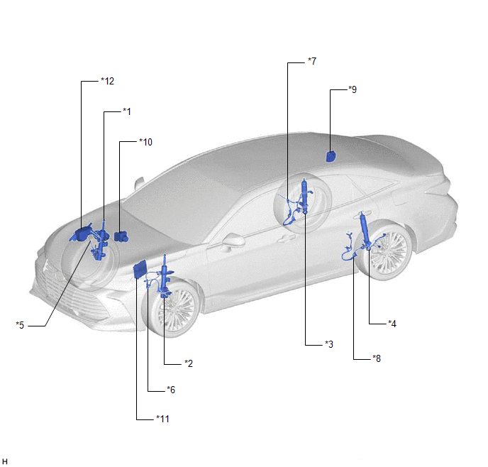
|
*1 | FRONT ABSORBER CONTROL ACTUATOR RH (FRONT SHOCK ABSORBER ASSEMBLY RH) |
*2 | FRONT ABSORBER CONTROL ACTUATOR LH (FRONT SHOCK ABSORBER ASSEMBLY LH) |
|
*3 | REAR ABSORBER CONTROL ACTUATOR RH (REAR SHOCK ABSORBER ASSEMBLY RH) |
*4 | REAR ABSORBER CONTROL ACTUATOR LH (REAR SHOCK ABSORBER ASSEMBLY LH) |
|
*5 | FRONT SKID CONTROL SENSOR WIRE RH |
*6 | FRONT SKID CONTROL SENSOR WIRE LH |
|
*7 | SKID CONTROL SENSOR WIRE RH (NO. 1 PARKING BRAKE WIRE ASSEMBLY) |
*8 | SKID CONTROL SENSOR WIRE LH (NO. 2 PARKING BRAKE WIRE ASSEMBLY) |
|
*9 | ABSORBER CONTROL ECU |
*10 | SKID CONTROL ECU (BRAKE ACTUATOR ASSEMBLY) |
|
*11 | ECM |
*12 | NO. 2 ENGINE ROOM RELAY BLOCK AND NO. 2 JUNCTION BLOCK ASSEMBLY - IG1 NO. 3 RELAY - AVS FUSE |
ILLUSTRATION
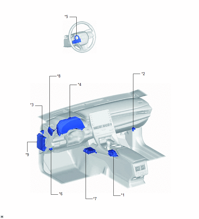
|
*1 | DRIVE MODE SELECT SWITCH (ELECTRIC PARKING BRAKE SWITCH ASSEMBLY) |
*2 | ACCELERATION SENSOR ASSEMBLY RH |
|
*3 | ACCELERATION SENSOR ASSEMBLY LH |
*4 | COMBINATION METER ASSEMBLY |
|
*5 | STEERING SENSOR |
*6 | DLC3 |
|
*7 | AIRBAG ECU ASSEMBLY |
*8 | DRIVING SUPPORT ECU ASSEMBLY |
|
*9 | INSTRUMENT PANEL JUNCTION BLOCK ASSEMBLY - ECU-IG1 NO. 3 FUSE |
- | - |
PRECAUTION
PRECAUTION FOR DISCONNECTING CABLE FROM NEGATIVE BATTERY TERMINAL
NOTICE:
When disconnecting the cable from the negative (-) battery terminal, initialize the following systems after the cable is reconnected.
|
System Name | See Procedure |
|---|---|
|
Lane Departure Alert System (w/ Steering Control) |
|
|
Intelligent Clearance Sonar System | |
|
Parking Assist Monitor System | |
|
Panoramic View Monitor System | |
|
Pre-collision System | |
|
Lighting System (for Gasoline Model with Cornering Light) |
ADAPTIVE VARIABLE SUSPENSION SYSTEM PRECAUTION
NOTICE:
Click here 
SYSTEM DESCRIPTION
ADAPTIVE VARIABLE SUSPENSION SYSTEM DESCRIPTION
(a) The ECM judges the mode based on the input from the drive mode select switch (electric parking brake switch assembly). The absorber control ECU receives the judgment result via CAN communication and controls the adaptive variable suspension.
SYSTEM DIAGRAM
TERMINALS OF ECU
CHECK ABSORBER CONTROL ECU

(a) Measure the voltage and resistance according to the value(s) in the table below.
NOTICE:
Inspect the connectors from the back side while the connectors are connected.
|
Terminal No. (Symbol) | Wiring Color |
Terminal Description | Condition |
Specified Condition |
|---|---|---|---|---|
|
K59-1 (IGB) - K59-4 (GND) |
GR - W-B | IG power supply |
Engine switch on (IG) |
11 to 14 V |
|
K59-4 (GND) - Body ground |
W-B - Body ground | Ground |
Always | Below 1 Ω |
|
K59-8 (CANH) - K59-7 (CANL) |
B - W | CAN communication line |
Engine switch off | 54 to 69 Ω |
|
K59-14 (SGB1) - K59-4 (GND) |
R - W-B | Acceleration sensor RH power source |
Engine switch on (IG) |
4.75 to 5.25 V |
|
K59-15 (SGB2) - K59-4 (GND) |
SB - W-B | Acceleration sensor LH power source |
Engine switch on (IG) |
4.75 to 5.25 V |
|
K59-22 (SGG1) - K59-4 (GND) |
G - W-B | Acceleration sensor RH ground |
Always | Below 1 Ω |
|
K59-23 (SGS1) - K59-4 (GND) |
L - W-B | Acceleration sensor RH signal input |
Engine switch on (IG) with vehicle stationary |
2.1 to 2.9 V |
|
K59-24 (SGG2) - K59-4 (GND) |
LG - W-B | Acceleration sensor LH ground |
Always | Below 1 Ω |
|
K59-25 (SGS2) - K59-4 (GND) |
W - W-B | Acceleration sensor LH signal input |
Engine switch on (IG) with vehicle stationary |
2.1 to 2.9 V |
TEST MODE PROCEDURE
TEST MODE PROCEDURE
NOTICE:
After replacing the absorber control ECU, it is necessary to perform registration of vehicle identification information. Vehicle identification information is automatically acquired when the system enters test mode.
HINT:
(a) Turn the engine switch off.
(b) Connect the Techstream to the DLC3.
(c) Turn the engine switch on (IG).
(d) Turn the Techstream on.
(e) Enter the following menus: Chassis / Air suspension / Utility / Signal Check.
Chassis > Air suspension > Utility|
Tester Display |
|---|
| Signal Check |
(f) Confirm that the system is in test mode by checking that the "Sport S+" indicator in the combination meter assembly is blinking at approximately 0.1-second intervals (0.1 seconds on and 0.1 seconds off).
HINT:
When vehicle identification information has not been acquired, the "Sport S+" indicator in the combination meter assembly blinks at approximately 1-second intervals (1 second on and 1 second off). After vehicle identification information is acquired, the "Sport S+" indicator in the combination meter assembly blinks at approximately 0.1-second intervals (0.1 seconds on and 0.1 seconds off).
(g) With the vehicle stationary on a level surface, wait for 1 second or more.
(h) Read the test mode DTCs by following the prompts on the Techstream screen.
(i) End test mode by following the prompts on the Techstream screen.
(j) Turn the engine switch off and disconnect the Techstream from the DLC3.
TEST MODE DTC CHART
(a) If a trouble code is output during the test mode DTC check, check the circuit listed for that code. For details of each code, refer to Link for the respective DTC in the chart.
|
DTC Code | Detection Item |
Trouble Area | Deletion Condition |
Link |
|---|---|---|---|---|
| C1796 |
(Up&Down)G Sensor FR |
| With the vehicle stationary on a level surface, an acceleration sensor value that is within -1.96 to 1.96 m/s2 is received from the acceleration sensor for 1 second or more. |
|
|
C1797 | (Up&Down)G Sensor FL |
| ||
| C1798 |
(Up&Down)G Sensor Rear |
Absorber control ECU |
DESCRIPTION
The absorber control ECU receives signals from the ECM, skid control ECU (brake actuator assembly), airbag ECU assembly and steering sensor via CAN communication.
When DTCs indicating a CAN communication system malfunction are output, repair the CAN communication system first.
|
DTC No. | Detection Item |
DTC Detection Condition | Trouble Area |
Warning Indicate | Memory |
|---|---|---|---|---|---|
|
U0100 | Lost Communication With ECM/PCM "A" |
While driving at 30 km/h (19 mph) or more, data is not received via CAN communication for 3 seconds or more. |
| Does not come on |
Yes |
| U0101 |
Lost Communication with TCM |
While driving at 30 km/h (19 mph) or more, data is not received via CAN communication for 6 seconds or more. |
| Does not come on |
Yes |
| U0122 |
Lost Communication With Vehicle Dynamics Control Module |
Data is not received from the skid control ECU (brake actuator assembly) via CAN communication for 3 seconds or more. |
| Does not come on |
Yes |
| U0124 |
Lost Communication with Lateral Acceleration Sensor Module |
Data is not received from the airbag ECU assembly via CAN communication for 3 seconds or more. |
| Does not come on |
Yes |
| U0126 |
Lost Communication with Steering Angle Sensor Module |
Data is not received from the steering sensor via CAN communication for 3 seconds or more. |
| Does not come on |
Yes |
CAUTION / NOTICE / HINT
NOTICE:
Click here 
Click here
Click here
Click here
Click here
PROCEDURE
|
1. | CHECK FOR DTCS |
(a) Clear the DTCs.
Click here
(b) Turn the engine switch off.
(c) Drive the vehicle at a speed of 30 km/h (19 mph) or more for 10 seconds or more.
(d) Check for DTCs.
Click here
|
Result | Proceed to |
|---|---|
|
CAN DTCs are not output |
A |
| CAN DTCs are output |
B |
HINT:
If a CAN communication malfunction DTC and a related sensor malfunction DTC are output at the same time, the CAN communication malfunction must be repaired before troubleshooting the sensor.
| A |
 | USE SIMULATION METHOD TO CHECK |
| B |
| GO TO CAN COMMUNICATION SYSTEM (HOW TO PROCEED WITH TROUBLESHOOTING) |
Toyota Avalon (XX50) 2019-2022 Service & Repair Manual > Theft Deterrent / Keyless Entry: Electrical Key Oscillator(for Front Floor)
ComponentsCOMPONENTS ILLUSTRATION *1 CONSOLE ASSEMBLY *2 NO. 1 INDOOR ELECTRICAL KEY ANTENNA ASSEMBLY InstallationINSTALLATION PROCEDURE 1. INSTALL NO. 1 INDOOR ELECTRICAL KEY ANTENNA ASSEMBLY (a) Engage the clamp to install the No. 1 indoor electrical key antenna assembly. NOTICE: Be careful when ...


