COMPONENTS
ILLUSTRATION
|
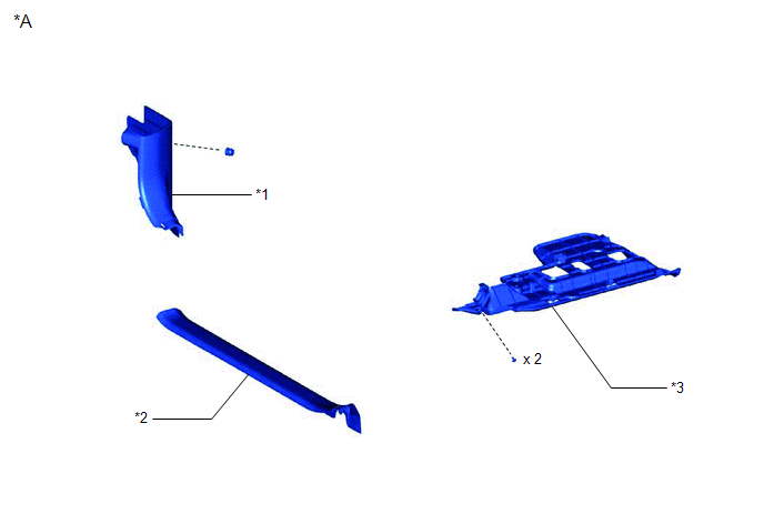
*A | for LH Side |
- | - |
|
*1 | COWL SIDE TRIM SUB-ASSEMBLY LH |
*2 | FRONT DOOR SCUFF PLATE LH |
|
*3 | NO. 1 INSTRUMENT PANEL UNDER COVER SUB-ASSEMBLY |
- | - |
ILLUSTRATION
|
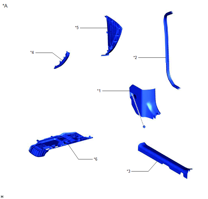
*A | for RH Side |
- | - |
|
*1 | COWL SIDE TRIM SUB-ASSEMBLY RH |
*2 | FRONT DOOR OPENING TRIM WEATHERSTRIP RH |
|
*3 | FRONT DOOR SCUFF PLATE RH |
*4 | GLOVE COMPARTMENT PLATE |
|
*5 | INSTRUMENT SIDE PANEL RH |
*6 | NO. 2 INSTRUMENT PANEL UNDER COVER SUB-ASSEMBLY |
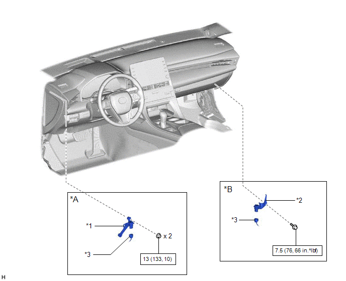
ILLUSTRATION
|
*A | for LH Side |
*B | for RH Side |
|
*1 | ACCELERATION SENSOR ASSEMBLY LH |
*2 | ACCELERATION SENSOR ASSEMBLY RH |
|
*3 | CONNECTOR |
- | - |
 |
N*m (kgf*cm, ft.*lbf): Specified torque |
- | - |
INSPECTION
PROCEDURE
1. INSPECT ACCELERATION SENSOR ASSEMBLY
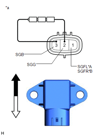
(a) Connect 3 1.5 V dry cell batteries in series.
(b) Connect a positive (+) lead from the batteries to terminal 3 (SGB) and a negative (-) lead to terminal 2 (SGG).
(c) Measure the voltage according to the value(s) in the table below.
Standard Voltage:
for LH Side|
Tester Connection | Condition |
Specified Condition |
|---|---|---|
|
1 (SGFL) - 2 (SGG) | Sensor stationary |
Approx. 2.0 to 2.5 V |
|
Sensor vibrating vertically |
Changes between approx. 0.9 and 3.6 V |
|
Tester Connection | Condition |
Specified Condition |
|---|---|---|
|
1 (SGFR) - 2 (SGG) | Sensor stationary |
Approx. 2.0 to 2.5 V |
|
Sensor vibrating vertically |
Changes between approx. 0.9 and 3.6 V |
|
*A | for LH Side |
|
*B | for RH Side |
|
*a | Component without harness connected (Front Acceleration Sensor Assembly) |
 |
Top |
 | Bottom |
NOTICE:
HINT:
When the front acceleration sensor assembly is tilted, it may output a different value.
If the result is not as specified, replace the front acceleration sensor assembly.
INSTALLATION
PROCEDURE
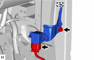
1. INSTALL ACCELERATION SENSOR ASSEMBLY LH (for LH Side)
| (a) Install the acceleration sensor assembly LH with the 2 nuts. Torque: 13 N·m {133 kgf·cm, 10 ft·lbf} NOTICE:
|
|
(b) Engage the clamp.
(c) Connect the connector to the acceleration sensor assembly LH.
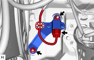
2. INSTALL ACCELERATION SENSOR ASSEMBLY RH (for RH Side)
| (a) Insert the guide to the body hole and install the acceleration sensor assembly RH with the bolt. Torque: 7.5 N·m {76 kgf·cm, 66 in·lbf} NOTICE:
|
|
(b) Connect the connector to the acceleration sensor assembly RH.
3. INSTALL NO. 1 INSTRUMENT PANEL UNDER COVER SUB-ASSEMBLY (for LH Side)
Click here 
4. INSTALL COWL SIDE TRIM SUB-ASSEMBLY LH (for LH Side)
Click here
5. INSTALL FRONT DOOR SCUFF PLATE LH (for LH Side)
Click here
6. INSTALL NO. 2 INSTRUMENT PANEL UNDER COVER SUB-ASSEMBLY (for RH Side)
Click here
7. INSTALL INSTRUMENT SIDE PANEL RH (for RH Side)
Click here
8. INSTALL GLOVE COMPARTMENT PLATE (for RH Side)
Click here
9. CONNECT FRONT DOOR OPENING TRIM WEATHERSTRIP RH (for RH Side)
10. INSTALL COWL SIDE TRIM SUB-ASSEMBLY RH (for RH Side)
HINT:
Use the same procedure as for the LH side.
Click here
11. INSTALL FRONT DOOR SCUFF PLATE RH (for RH Side)
HINT:
Use the same procedure as for the LH side.
Click here
REMOVAL
PROCEDURE
1. REMOVE FRONT DOOR SCUFF PLATE LH (for LH Side)
Click here 
2. REMOVE COWL SIDE TRIM SUB-ASSEMBLY LH (for LH Side)
Click here
3. REMOVE NO. 1 INSTRUMENT PANEL UNDER COVER SUB-ASSEMBLY (for LH Side)
Click here
4. REMOVE FRONT DOOR SCUFF PLATE RH (for RH Side)
HINT:
Use the same procedure as for the LH side.
Click here
5. REMOVE COWL SIDE TRIM SUB-ASSEMBLY RH (for RH Side)
HINT:
Use the same procedure as for the LH side.
Click here
6. DISCONNECT FRONT DOOR OPENING TRIM WEATHERSTRIP RH (for RH Side)
HINT:
Disconnect the front door opening trim weatherstrip RH to the extent that allows the removal of the instrument side panel RH.
7. REMOVE GLOVE COMPARTMENT PLATE (for RH Side)
Click here
8. REMOVE INSTRUMENT SIDE PANEL RH (for RH Side)
Click here
9. REMOVE NO. 2 INSTRUMENT PANEL UNDER COVER SUB-ASSEMBLY (for RH Side)
Click here
10. REMOVE ACCELERATION SENSOR ASSEMBLY LH (for LH Side)
| (a) Disconnect the connector from the acceleration sensor assembly LH. |
|
(b) Disengage the clamp.
(c) Remove the 2 nuts and acceleration sensor assembly LH.
NOTICE:
11. REMOVE ACCELERATION SENSOR ASSEMBLY RH (for RH Side)
| (a) Disconnect the connector from the acceleration sensor assembly RH. |
|
(b) Remove the bolt and acceleration sensor assembly RH.
NOTICE:
Toyota Avalon (XX50) 2019-2022 Owners Manual > For safe use: Exhaust gas
precautions
Harmful substance to the human body is included in exhaust gases if inhaled. WARNINGExhaust gases include harmful carbon monoxide (CO), which is colorless and odorless. Observe the following precautions. Failure to do so may cause exhaust gases enter the vehicle and may lead to an accident c ...