DESCRIPTION
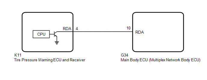
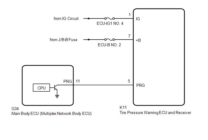
The main body ECU (multiplex network body ECU) and tire pressure warning ECU and receiver communicate by direct line. If a malfunction occurs in this communication signal, B1247 is output by the main body ECU (multiplex network body ECU).
|
DTC No. | Detection Item |
DTC Detection Condition | Trouble Area |
Note |
|---|---|---|---|---|
| B1247 |
Tire Pressure Monitor Receiver Communication Stop |
Communication between the tire pressure warning ECU and receiver and main body ECU (multiplex network body ECU) is interrupted for 10 seconds or more. |
| This DTC is for main body ECU (multiplex network body ECU) |
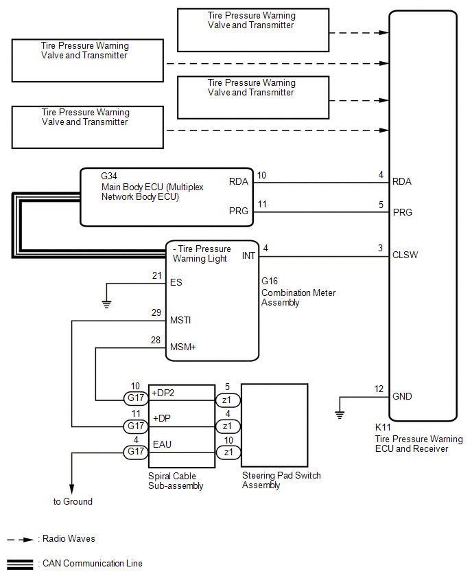
WIRING DIAGRAM
CAUTION / NOTICE / HINT
NOTICE:
 after registration
of the transmitter IDs into the tire pressure warning ECU and receiver after the ECU has been replaced.
after registration
of the transmitter IDs into the tire pressure warning ECU and receiver after the ECU has been replaced.
Click here
PROCEDURE
|
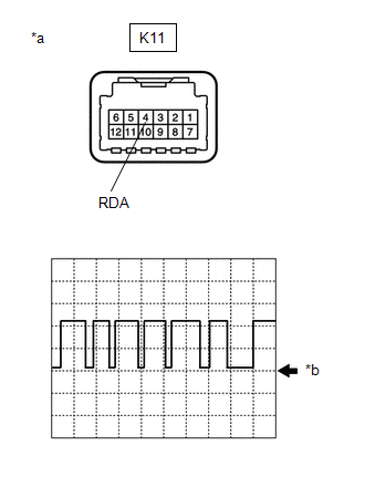
1. | INSPECT TIRE PRESSURE WARNING ECU AND RECEIVER (OUTPUT WAVEFORM) |
| (a) Using an oscilloscope, check the waveform. NOTICE: With the connector connected, check from the backside of the connector. Standard Voltage:
|
|
|
Result | Proceed to |
|---|---|
|
Waveform is as shown in the illustration. (Waveform alternates between 10.5 V or higher and 0.5 V or less) |
A |
| Waveform does not change from 10.5 V or higher |
B |
| Waveform does not change from 0.5 V or less |
C |
| A |
 | REPLACE MAIN BODY ECU (MULTIPLEX NETWORK BODY ECU) |
| B |
| REPLACE TIRE PRESSURE WARNING ECU AND RECEIVER |
|
| 2. |
CHECK TERMINAL VOLTAGE (MAIN BODY ECU (MULTIPLEX NETWORK BODY ECU) OUTPUT) |
(a) Disconnect the K11 tire pressure warning ECU and receiver connector.
(b) Measure the voltage according to the value(s) in the table below.
Standard Voltage:
|
Tester Connection | Condition |
Specified Condition |
|---|---|---|
|
K11-4 (RDA) - Body ground |
Engine switch on (IG) |
10.5 V or higher |
| OK | | REPLACE TIRE PRESSURE WARNING ECU AND RECEIVER |
|
| 3. |
CHECK HARNESS AND CONNECTOR (MAIN BODY ECU (MULTIPLEX NETWORK BODY ECU) - TIRE PRESSURE WARNING ECU AND RECEIVER) |
(a) Turn the engine switch off.
(b) Disconnect the G34 main body ECU (multiplex network body ECU) connector.
(c) Measure the resistance according to the value(s) in the table below.
Standard Resistance:
|
Tester Connection | Condition |
Specified Condition |
|---|---|---|
|
G34-10 (RDA) - K11-4 (RDA) |
Always | Below 1 Ω |
|
G34-10 (RDA) or K11-4 (RDA) - Body ground |
Always | 10 kΩ or higher |
| OK | | REPLACE MAIN BODY ECU (MULTIPLEX NETWORK BODY ECU) |
| NG | | REPAIR OR REPLACE HARNESS OR CONNECTOR |
DESCRIPTION
The tire pressure warning valve and transmitters that are installed in the tire and wheel assemblies measure the tire pressure of each wheel. The measured values are transmitted to the tire pressure warning ECU and receiver in the vehicle as radio waves. The ECU compares the measured tire pressure values with the tire pressure threshold. When the measured tire pressure value is less than this threshold, the warning light in the combination meter assembly illuminates. The tire pressure warning ECU and receiver stores a DTC when the tire pressure warning valve and transmitter stops transmitting signals. The signals can be forcibly transmitted by releasing the tire pressure rapidly. The stored DTCs are cleared when signal transmission resumes.
|
DTC No. | Detection Item |
DTC Detection Condition | Trouble Area |
Note |
|---|---|---|---|---|
| C2111 |
Transmitter ID1 Operation Stop |
Tire pressure warning valve and transmitters stop transmitting signals |
| - |
|
C2112 | Transmitter ID2 Operation Stop |
Tire pressure warning valve and transmitters stop transmitting signals |
| - |
|
C2113 | Transmitter ID3 Operation Stop |
Tire pressure warning valve and transmitters stop transmitting signals |
| - |
|
C2114 | Transmitter ID4 Operation Stop |
Tire pressure warning valve and transmitters stop transmitting signals |
| - |
HINT:
It is necessary to perform the following procedure to identify the tire pressure warning valve and transmitter that is malfunctioning because it cannot be identified by the output DTC.
WIRING DIAGRAM

PROCEDURE
| 1. |
PERFORM FORCED TRANSMISSION OF TRANSMITTER ID OF ALL WHEELS |
(a) Set the tire pressure to the specified value.
Click here

(b) Turn the engine switch off.
(c) Connect the Techstream to the DLC3.
(d) Turn the engine switch on (IG).
(e) Turn the Techstream on.
(f) Enter the following menus: Chassis / Tire Pressure Monitor / Data List.
(g) Read the Data List according to the display on the Techstream.
Chassis > Tire Pressure Monitor > Data List|
Tester Display | Measurement Item |
Range | Normal Condition |
Diagnostic Note |
|---|---|---|---|---|
|
ID 1 Tire Inflation Pressure |
ID1 tire inflation pressure |
min.: Absolute pressure (abs) / 0 kPa (0 kgf/cm2, 0 psi), Relative pressure (Gauge) / 0 kPa (0 kgf/cm2, 0 psi) max.: Absolute pressure (abs) / 480 kPa (4.9 kgf/cm2, 70 psi), Relative pressure (Gauge) / 380 kPa (3.9 kgf/cm2, 55 psi) |
Actual tire inflation pressure |
If N/A is displayed, data has not been received.*1 |
|
ID 2 Tire Inflation Pressure |
ID2 tire inflation pressure |
min.: Absolute pressure (abs) / 0 kPa (0 kgf/cm2, 0 psi), Relative pressure (Gauge) / 0 kPa (0 kgf/cm2, 0 psi) max.: Absolute pressure (abs) / 480 kPa (4.9 kgf/cm2, 70 psi), Relative pressure (Gauge) / 380 kPa (3.9 kgf/cm2, 55 psi) |
Actual tire inflation pressure |
If N/A is displayed, data has not been received.*1 |
|
ID 3 Tire Inflation Pressure |
ID3 tire inflation pressure |
min.: Absolute pressure (abs) / 0 kPa (0 kgf/cm2, 0 psi), Relative pressure (Gauge) / 0 kPa (0 kgf/cm2, 0 psi) max.: Absolute pressure (abs) / 480 kPa (4.9 kgf/cm2, 70 psi), Relative pressure (Gauge) / 380 kPa (3.9 kgf/cm2, 55 psi) |
Actual tire inflation pressure |
If N/A is displayed, data has not been received.*1 |
|
ID 4 Tire Inflation Pressure |
ID4 tire inflation pressure |
min.: Absolute pressure (abs) / 0 kPa (0 kgf/cm2, 0 psi), Relative pressure (Gauge) / 0 kPa (0 kgf/cm2, 0 psi) max.: Absolute pressure (abs) / 480 kPa (4.9 kgf/cm2, 70 psi), Relative pressure (Gauge) / 380 kPa (3.9 kgf/cm2, 55 psi) |
Actual tire inflation pressure |
If N/A is displayed, data has not been received.*1 |
HINT:
*1: It may take a few minutes until the values are displayed. If the values are not displayed after a few minutes, perform troubleshooting according to the inspection procedure for DTCs C2121 to C2124.
Click here
|
Tester Display |
|---|
| ID 1 Tire Inflation Pressure |
|
ID 2 Tire Inflation Pressure |
|
ID 3 Tire Inflation Pressure |
|
ID 4 Tire Inflation Pressure |
(h) Rapidly reduce the tire pressure for each wheel at least 40 kPa (0.4 kgf/cm2, 5.8 psi) within 30 seconds.
(1) Check that each "ID Tire Inflation Pressure" value displayed on the Techstream has changed.
OK:
Each "ID Tire Inflation Pressure" value displayed on the Techstream changed to the actual tire inflation pressure value.
NOTICE:
(2) After confirming that all of the tire "ID Tire Inflation Pressure" values displayed on the Techstream have changed, set the tire pressure to the appropriate specified values.
HINT:
If an "ID Tire Inflation Pressure" value displayed on the Techstream has not changed after rechecking, inspect for another problem.
Click here
| OK |  |
END |
| NG | | GO TO TRANSMITTER AND RECEIVER INSPECTION PROCEDURE |
DESCRIPTION
The tire pressure warning valve and transmitters that are installed in the tire and wheel assemblies measure the tire pressure of each wheel. The measured values are transmitted to the tire pressure warning ECU and receiver in the vehicle as radio waves. The ECU compares the measured tire pressure values with the tire pressure threshold. When the measured tire pressure value is less than this threshold, the warning light in the combination meter assembly illuminates.
The tire pressure warning valve and transmitters constantly send radio waves to the tire pressure warning ECU and receiver.
Under the conditions below, the tire pressure warning ECU and receiver is unable to receive the signals from the tire pressure warning valve and transmitters, and a DTC is stored.
HINT:
When no transmitter ID is received from a tire pressure warning valve and transmitter for 20 minutes or more while the vehicle speed is more than 40 km/h (25 mph), or no transmitter ID is received from all of the tire pressure warning valve and transmitters for 20 minutes or more, DTCs from C2121 to C2124 are stored.
DTCs C2121 to C2124 can only be cleared by using the Techstream. DTCs C2181 to C2184 can be cleared when the tire pressure warning valve and transmitter sends a forced transmission signal or test mode ends. DTCs C2181 to C2184 are output only in test mode.
|
DTC No. | Detection Item |
DTC Detection Condition | Trouble Area |
Note |
|---|---|---|---|---|
| C2121 |
Transmitter ID 1 not Received (Main) |
Either of the following conditions (a) or (b) is met: (a) When all conditions below are met:
(b) When both conditions below are met:
|
| - |
|
C2122 | Transmitter ID 2 not Received (Main) |
Either of the following conditions (a) or (b) is met: (a) When all conditions below are met:
(b) When both conditions below are met:
|
| - |
|
C2123 | Transmitter ID 3 not Received (Main) |
Either of the following conditions (a) or (b) is met: (a) When all conditions below are met:
(b) When both conditions below are met:
|
| - |
|
C2124 | Transmitter ID 4 not Received (Main) |
Either of the following conditions (a) or (b) is met: (a) When all conditions below are met:
(b) When both conditions below are met:
|
| - |
|
C2181 | Transmitter ID 1 not Received (for Test Diagnosis) |
Test mode procedure is performed. |
| - |
|
C2182 | Transmitter ID 2 not Received (for Test Diagnosis) |
Test mode procedure is performed. |
| - |
|
C2183 | Transmitter ID 3 not Received (for Test Diagnosis) |
Test mode procedure is performed. |
| - |
|
C2184 | Transmitter ID 4 not Received (for Test Diagnosis) |
Test mode procedure is performed. |
| - |
NOTICE:
HINT:
It is necessary to perform the following procedure to identify the tire pressure warning valve and transmitter that is malfunctioning because it cannot be identified by the output DTC.
WIRING DIAGRAM
CAUTION / NOTICE / HINT
NOTICE:
 after registration
of the transmitter IDs into the tire pressure warning ECU and receiver
if the ECU and/or one of the valve and transmitters has been replaced.
after registration
of the transmitter IDs into the tire pressure warning ECU and receiver
if the ECU and/or one of the valve and transmitters has been replaced.
PROCEDURE
|
1. | CHECK FREQUENCY RECEIVING CONDITION |
(a) Check that the following conditions are not met:
(1) Facilities or devices that use similar radio frequencies are located in the vicinity of the vehicle.
HINT:
If the vehicle is located in an area such as the one described above, the tire pressure warning light may illuminate after blinking for 1 minute due to interfering radio frequencies.
(2) Devices using similar radio frequencies are used in the vehicle.
HINT:
Radio transmissions may be interrupted due to the surroundings or devices installed by the user.
|
Result | Proceed to |
|---|---|
|
There is no device or facility that uses electrical waves of approximately the same frequency in the vicinity of the vehicle or inside the vehicle. |
A |
| There is a device or facility that uses electrical waves of approximately the same frequency in the vicinity of the vehicle or inside the vehicle. |
B |
| B |
 | GO TO STEP 10 |
|
| 2. |
CONFIRM OUTPUT DTC |
(a) Check the stored DTC.
|
Result | Proceed to |
|---|---|
|
Any DTCs from C2121 to C2124 are output (C2181 to C2184 when in Test Mode) |
A |
| All DTCs from C2121 to C2124 are output (C2181 to C2184 when in Test Mode) |
B |
| B |
| GO TO STEP 5 |
|
| 3. |
IDENTIFY TRANSMITTER CORRESPONDING TO DTC (TIRE POSITION) |
(a) Turn the engine switch off.
(b) Connect the Techstream to the DLC3.
(c) Turn the engine switch on (IG).
(d) Turn the Techstream on.
(e) Enter the following menus: Chassis / Tire Pressure Monitor / Data List.
(f) Display the "ID Tire Position" value for each wheel using the Techstream.
(g) Refer to the following chart and check the wheel position of the DTC and transmitter match.
Chassis > Tire Pressure Monitor > Data List|
Tester Display | Measurement Item |
Range | Normal Condition |
Diagnostic Note |
|---|---|---|---|---|
|
ID 1 Tire Position | ID1 Tire Position |
No Information or FL or FR or RL or RR or Spare or Judging |
ID1 tire position is displayed |
If no tire position information is stored, "No Information" will be displayed. |
|
ID 2 Tire Position | ID2 Tire Position |
No Information or FL or FR or RL or RR or Spare or Judging |
ID2 tire position is displayed |
If no tire position information is stored, "No Information" will be displayed. |
|
ID 3 Tire Position | ID3 Tire Position |
No Information or FL or FR or RL or RR or Spare or Judging |
ID3 tire position is displayed |
If no tire position information is stored, "No Information" will be displayed. |
|
ID 4 Tire Position | ID4 Tire Position |
No Information or FL or FR or RL or RR or Spare or Judging |
ID4 tire position is displayed |
If no tire position information is stored, "No Information" will be displayed. |
HINT:
Refer to the following chart for the Data List items that correspond to the DTCs.
|
DTC No. | Detection Item |
Data List |
|---|---|---|
| C2121 |
Transmitter ID 1 not Received (Main) |
ID1 Tire Position |
|
C2181 | Transmitter ID 1 not Received (for Test Diagnosis) | |
|
C2122 | Transmitter ID 2 not Received (Main) |
ID2 Tire Position |
|
C2182 | Transmitter ID 2 not Received (for Test Diagnosis) | |
|
C2123 | Transmitter ID 3 not Received (Main) |
ID3 Tire Position |
|
C2183 | Transmitter ID 3 not Received (for Test Diagnosis) | |
|
C2124 | Transmitter ID 4 not Received (Main) |
ID4 Tire Position |
|
C2184 | Transmitter ID 4 not Received (for Test Diagnosis) |
|
Tester Display |
|---|
| ID 1 Tire Position |
|
ID 2 Tire Position |
|
ID 3 Tire Position |
|
ID 4 Tire Position |
|
| 4. |
CHECK TRANSMITTER ID |
(a) Turn the engine switch off.
(b) Connect the Techstream to the DLC3.
(c) Turn the engine switch on (IG).
(d) Turn the Techstream on.
(e) Enter the following menus: Chassis / Tire Pressure Monitor / Data List.
(f) Refer to the following chart and record the tire pressure warning valve and transmitter ID of the output DTC.
Chassis > Tire Pressure Monitor > Data List|
Tester Display | Measurement Item |
Range | Normal Condition |
Diagnostic Note |
|---|---|---|---|---|
|
Registered ID 1 Code | Registered ID1 code |
min.: 0 max.: FFFFFFF*1 |
ID No. registered for transmitter ID1 displayed |
- |
| Registered ID 2 Code |
Registered ID2 code | min.: 0 max.: FFFFFFF*1 | ID No. registered for transmitter ID2 displayed |
- |
| Registered ID 3 Code |
Registered ID3 code | min.: 0 max.: FFFFFFF*1 | ID No. registered for transmitter ID3 displayed |
- |
| Registered ID 4 Code |
Registered ID4 code | min.: 0 max.: FFFFFFF*1 | ID No. registered for transmitter ID4 displayed |
- |
HINT:
|
DTC No. |
Detection Item |
Data List |
|---|---|---|
|
C2121 |
Transmitter ID 1 not Received (Main) |
Registered ID 1 code |
|
C2181 |
Transmitter ID 1 not Received (for Test Diagnosis) |
|
|
C2122 |
Transmitter ID 2 not Received (Main) |
Registered ID 2 code |
|
C2182 |
Transmitter ID 2 not Received (for Test Diagnosis) |
|
|
C2123 |
Transmitter ID 3 not Received (Main) |
Registered ID 3 code |
|
C2183 |
Transmitter ID 3 not Received (for Test Diagnosis) |
|
|
C2124 |
Transmitter ID 4 not Received (Main) |
Registered ID 4 code |
|
C2184 |
Transmitter ID 4 not Received (for Test Diagnosis) |
|
Tester Display |
|---|
| Registered ID 1 Code |
|
Registered ID 2 Code |
|
Registered ID 3 Code |
|
Registered ID 4 Code |
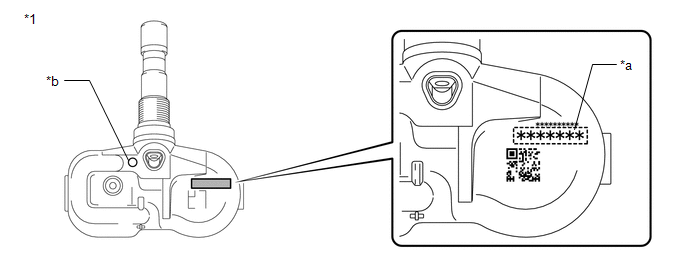
(g) Disassemble the tire indicated in the output DTC and check the tire pressure warning valve and transmitter ID.

|
*1 | Tire Pressure Warning Valve and Transmitter |
- | - |
|
*a | Transmitter ID (7-digit Number) |
*b | Wheel Speed Type Tire Inflation Pressure Display Function Identification Mark |
NOTICE:
For vehicles equipped with the wheel speed type tire inflation pressure display function, be sure to use tire pressure warning valve and transmitters with identification marks.
(h) Confirm that the ID number on the transmitter and recorded transmitter ID match.
|
Result | Proceed to |
|---|---|
|
Match | A |
|
Do not match | B |
| A |
| REPLACE TIRE PRESSURE WARNING VALVE AND TRANSMITTER |
| B |
| GO TO STEP 7 |
| 5. |
TEST MODE INSPECTION (C2181 to C2184) |
(a) Perform a test mode inspection and perform Transmitter Data Reception Check (C2181 to C2184).
Click here
| OK | | END |
|
| 6. |
CHECK TIRE PRESSURE WARNING VALVE AND TRANSMITTER |
(a) Turn the engine switch off.
(b) Connect the Techstream to the DLC3.
(c) Turn the engine switch on (IG).
(d) Turn the Techstream on.
(e) Enter the following menus: Chassis / Tire Pressure Monitor / Data List.
(f) Refer to the following chart and record all of the tire pressure warning valve and transmitter IDs.
Chassis > Tire Pressure Monitor > Data List|
Tester Display | Measurement Item |
Range | Normal Condition |
Diagnostic Note |
|---|---|---|---|---|
|
Registered ID 1 Code | Registered ID1 code |
min.: 0 max.: FFFFFFF*1 |
ID No. registered for transmitter ID1 displayed |
- |
| Registered ID 2 Code |
Registered ID2 code | min.: 0 max.: FFFFFFF*1 | ID No. registered for transmitter ID2 displayed |
- |
| Registered ID 3 Code |
Registered ID3 code | min.: 0 max.: FFFFFFF*1 | ID No. registered for transmitter ID3 displayed |
- |
| Registered ID 4 Code |
Registered ID4 code | min.: 0 max.: FFFFFFF*1 | ID No. registered for transmitter ID4 displayed |
- |
HINT:
|
Tester Display |
|---|
| Registered ID 1 Code |
|
Registered ID 2 Code |
|
Registered ID 3 Code |
|
Registered ID 4 Code |
(g) Disassemble all of the tires and check the tire pressure warning valve and transmitter IDs.
|
*1 | Tire Pressure Warning Valve and Transmitter |
- | - |
|
*a | Transmitter ID (7-digit Number) |
*b | Wheel Speed Type Tire Inflation Pressure Display Function Identification Mark |
NOTICE:
For vehicles equipped with the wheel speed type tire inflation pressure display function, be sure to use tire pressure warning valve and transmitters with identification marks.
(h) Confirm that the ID number on the transmitter and recorded transmitter ID match.
|
Result | Proceed to |
|---|---|
|
Match | A |
|
Do not match | B |
| A |
| REPLACE TIRE PRESSURE WARNING ECU AND RECEIVER |
|
| 7. |
REGISTRATION OF TRANSMITTER ID |
(a) Perform registration.
Click here
|
| 8. |
PERFORM INITIALIZATION |
(a) Perform initialization.
Click here
|
| 9. |
CLEAR DTC |
(a) Clear the DTCs.
Chassis > Tire Pressure Monitor > Clear DTCs| NEXT | | END |
| 10. |
CLEAR DTC |
(a) Clear the DTCs.
Chassis > Tire Pressure Monitor > Clear DTCs| NEXT | | END |
DESCRIPTION
If ID registration via the automatic ID registration function is canceled or the tire pressure warning ECU and receiver does not receive data from the tire pressure warning valve and transmitters after the tire pressure warning valve and transmitter ID registration is completed using the Techstream, the tire pressure warning ECU and receiver stores DTC C2126.
After ID registration is complete using the Techstream, the tire pressure warning light illuminates after blinking for 1 minute. When the tire pressure warning ECU and receiver receives the data from all tire pressure warning valve and transmitters with registered IDs, the tire pressure is judged to be normal and the tire pressure warning light turns off.
|
DTC No. | Detection Item |
DTC Detection Condition | Trouble Area |
Note |
|---|---|---|---|---|
| C2126 |
Transmitter ID not Received (Main) |
|
| - |
NOTICE:
If DTC C2126 is stored, C2128 may also be stored. If DTC C2128 is stored, perform troubleshooting for DTC C2128 before performing troubleshooting for DTC C2126.
HINT:
The purpose of this DTC is to help prevent delivering a vehicle that has incorrectly registered transmitter IDs. After all IDs are registered, DTC C2126 is detected and the tire pressure warning light blinks for 1 minute and then illuminates. If the tire pressure warning light does not go off after a little while, the transmitter IDs may be incorrectly registered.
CAUTION / NOTICE / HINT
NOTICE:
 after registration
of the transmitter IDs into the tire pressure warning ECU and receiver
if the ECU and/or one of the valve and transmitters has been replaced.
after registration
of the transmitter IDs into the tire pressure warning ECU and receiver
if the ECU and/or one of the valve and transmitters has been replaced.
PROCEDURE
|
1. | IDENTIFY TRANSMITTER NOT RECEIVED |
(a) Set the tire pressure to the specified value.
Click here
(b) Turn the engine switch off.
(c) Connect the Techstream to the DLC3.
(d) Turn the engine switch on (IG).
(e) Turn the Techstream on.
(f) Enter the following menus: Chassis / Tire Pressure Monitor / Data List.
(g) Display the "ID Tire Inflation Pressure" value for each wheel using the Techstream.
Chassis > Tire Pressure Monitor > Data List|
Tester Display | Measurement Item |
Range | Normal Condition |
Diagnostic Note |
|---|---|---|---|---|
|
ID 1 Tire Inflation Pressure |
ID1 tire inflation pressure |
min.: Absolute pressure (abs) / 0 kPa (0 kgf/cm2, 0 psi), Relative pressure (Gauge) / 0 kPa (0 kgf/cm2, 0 psi) max.: Absolute pressure (abs) / 480 kPa (4.9 kgf/cm2, 70 psi), Relative pressure (Gauge) / 380 kPa (3.9 kgf/cm2, 55 psi) |
Actual tire inflation pressure |
If N/A is displayed, data has not been received.*1 |
|
ID 2 Tire Inflation Pressure |
ID2 tire inflation pressure |
min.: Absolute pressure (abs) / 0 kPa (0 kgf/cm2, 0 psi), Relative pressure (Gauge) / 0 kPa (0 kgf/cm2, 0 psi) max.: Absolute pressure (abs) / 480 kPa (4.9 kgf/cm2, 70 psi), Relative pressure (Gauge) / 380 kPa (3.9 kgf/cm2, 55 psi) |
Actual tire inflation pressure |
If N/A is displayed, data has not been received.*1 |
|
ID 3 Tire Inflation Pressure |
ID3 tire inflation pressure |
min.: Absolute pressure (abs) / 0 kPa (0 kgf/cm2, 0 psi), Relative pressure (Gauge)/ 0 kPa (0 kgf/cm2, 0 psi) max.: Absolute pressure (abs) / 480 kPa (4.9 kgf/cm2, 70 psi), Relative pressure (Gauge) / 380 kPa (3.9 kgf/cm2, 55 psi) |
Actual tire inflation pressure |
If N/A is displayed, data has not been received.*1 |
|
ID 4 Tire Inflation Pressure |
ID4 tire inflation pressure |
min.: Absolute pressure (abs) / 0 kPa (0 kgf/cm2, 0 psi), Relative pressure (Gauge) / 0 kPa (0 kgf/cm2, 0 psi) max.: Absolute pressure (abs) / 480 kPa (4.9 kgf/cm2, 70 psi), Relative pressure (Gauge) / 380 kPa (3.9 kgf/cm2, 55 psi) |
Actual tire inflation pressure |
If N/A is displayed, data has not been received.*1 |
HINT:
|
Tester Display |
|---|
| ID 1 Tire Inflation Pressure |
|
ID 2 Tire Inflation Pressure |
|
ID 3 Tire Inflation Pressure |
|
ID 4 Tire Inflation Pressure |
(h) Rapidly reduce the tire pressure for each wheel at least 40 kPa (0.4 kg/cm2, 5.8 psi) within 30 seconds. If the "ID Tire Inflation Pressure" value displayed on the Techstream does not change, the tire pressure warning valve and transmitter corresponding to the unchanged "ID Tire Inflation Pressure" value was the cause of the output DTC.
HINT:
(i) Check the Data List.
NOTICE:
(j) After confirming that the "ID Tire Inflation Pressure" value for one tire has changed, repeat this procedure one by one. Identify the transmitter not received.
|
Result | Proceed to |
|---|---|
|
Change in all tire inflation pressure data |
A |
| No change in all tire inflation pressure data |
B |
| No change in any tire inflation pressure data |
C |
| A |
 | END |
| C |
| GO TO STEP 3 |
|
| 2. |
CHECK TRANSMITTER ID |
(a) Turn the engine switch off.
(b) Connect the Techstream to the DLC3.
(c) Turn the engine switch on (IG).
(d) Turn the Techstream on.
(e) Enter the following menus: Chassis / Tire Pressure Monitor / Data List.
(f) Read the Data List according to the display on the Techstream.
Chassis > Tire Pressure Monitor > Data List|
Tester Display | Measurement Item |
Range | Normal Condition |
Diagnostic Note |
|---|---|---|---|---|
|
Registered ID 1 Code | Registered ID1 code |
min.: 0 max.: FFFFFFF*1 |
ID No. registered for transmitter ID1 displayed |
- |
| Registered ID 2 Code |
Registered ID2 code | min.: 0 max.: FFFFFFF*1 | ID No. registered for transmitter ID2 displayed |
- |
| Registered ID 3 Code |
Registered ID3 code | min.: 0 max.: FFFFFFF*1 | ID No. registered for transmitter ID3 displayed |
- |
| Registered ID 4 Code |
Registered ID4 code | min.: 0 max.: FFFFFFF*1 | ID No. registered for transmitter ID4 displayed |
- |
HINT:
|
Tester Display |
|---|
| Registered ID 1 Code |
|
Registered ID 2 Code |
|
Registered ID 3 Code |
|
Registered ID 4 Code |
(g) Disassemble all of the tires and check the tire pressure warning valve and transmitter IDs.

|
*1 | Tire Pressure Warning Valve and Transmitter |
- | - |
|
*a | Transmitter ID (7-digit Number) |
*b | Wheel Speed Type Tire Inflation Pressure Display Function Identification Mark |
NOTICE:
For vehicles equipped with the wheel speed type tire inflation pressure display function, be sure to use tire pressure warning valve and transmitters with identification marks.
(h) Confirm that the ID number on the transmitter and recorded transmitter ID match.
|
Result | Proceed to |
|---|---|
|
Match | A |
|
Do not match | B |
| A |
| REPLACE TIRE PRESSURE WARNING ECU AND RECEIVER |
| B |
| GO TO STEP 4 |
| 3. |
CHECK TRANSMITTER ID |
(a) Turn the engine switch off.
(b) Connect the Techstream to the DLC3.
(c) Turn the engine switch on (IG).
(d) Turn the Techstream on.
(e) Enter the following menus: Chassis / Tire Pressure Monitor / Data List.
(f) Read the Data List according to the display on the Techstream.
Chassis > Tire Pressure Monitor > Data List|
Tester Display | Measurement Item |
Range | Normal Condition |
Diagnostic Note |
|---|---|---|---|---|
|
Registered ID 1 Code | Registered ID1 code |
min.: 0 max.: FFFFFFF*1 |
ID No. registered for transmitter ID1 displayed |
- |
| Registered ID 2 Code |
Registered ID2 code | min.: 0 max.: FFFFFFF*1 | ID No. registered for transmitter ID2 displayed |
- |
| Registered ID 3 Code |
Registered ID3 code | min.: 0 max.: FFFFFFF*1 | ID No. registered for transmitter ID3 displayed |
- |
| Registered ID 4 Code |
Registered ID4 code | min.: 0 max.: FFFFFFF*1 | ID No. registered for transmitter ID4 displayed |
- |
HINT:
|
Tester Display |
|---|
| Registered ID 1 Code |
|
Registered ID 2 Code |
|
Registered ID 3 Code |
|
Registered ID 4 Code |
(g) Disassemble all of the tires and check the tire pressure warning valve and transmitter IDs.
|
*1 | Tire Pressure Warning Valve and Transmitter |
- | - |
|
*a | Transmitter ID (7-digit Number) |
*b | Wheel Speed Type Tire Inflation Pressure Display Function Identification Mark |
NOTICE:
For vehicles equipped with the wheel speed type tire inflation pressure display function, be sure to use tire pressure warning valve and transmitters with identification marks.
(h) Confirm that the ID number on the transmitter and recorded transmitter ID match.
|
Result | Proceed to |
|---|---|
|
Match | A |
|
Do not match | B |
| A |
| REPLACE TIRE PRESSURE WARNING VALVE AND TRANSMITTER |
|
| 4. |
REGISTRATION OF TRANSMITTER ID |
(a) Perform registration.
Click here
|
| 5. |
PERFORM INITIALIZATION |
(a) Perform initialization.
Click here
| NEXT | | END |
DESCRIPTION
When ID registration is being performed via the automatic ID registration function, the tire pressure warning ECU and receiver stores C2128 and the tire pressure warning light flashes for 1 minute and then illuminates.
When the tire pressure warning ECU receives data from all registered tire pressure warning valve and transmitters and the system is judged to be normal, the tire pressure warning light turns off.
|
DTC No. | Detection Item |
DTC Detection Condition | Trouble Area |
Note |
|---|---|---|---|---|
| C2128 |
Auto ID Under Registration |
ID registration is being performed via the automatic ID registration function |
Electronically controlled brake system |
- |
PROCEDURE
| 1. |
CHECK FOR DTC (ELECTRONICALLY CONTROLLED BRAKE SYSTEM) |
(a) Turn the engine switch on (IG).
(b) Check if the electronically controlled brake system DTCs are output.
Chassis > ABS/VSC/TRAC/EPB > Trouble CodesHINT:
If DTC C2128 is stored, electronically controlled brake system DTCs may also be stored. If electronically controlled brake system DTCs are stored, perform troubleshooting for the electronically controlled brake system before performing ID registration via the automatic ID registration function.
|
Result | Proceed to |
|---|---|
|
DTCs are not output | A |
|
DTCs are output | B |
| B |
 | GO TO ELECTRONICALLY CONTROLLED BRAKE SYSTEM |
|
| 2. |
REGISTRATION OF TRANSMITTER ID (ID REGISTRATION VIA AUTOMATIC ID REGISTRATION FUNCTION) |
(a) Turn the engine switch off.
(b) Turn the engine switch on (IG).
(c) Perform ID registration for the tire pressure warning ECU and receiver (ID registration via the automatic ID registration function).
Click here

HINT:
Perform the following procedures within 1 trip and do not turn the engine switch off.
|
| 3. |
READ VALUE USING TECHSTREAM ([RAM] AUTO ID REGISTERED WHEEL JUDGMENT STATUS) |
(a) Connect the Techstream to the DLC3.
(b) Turn the Techstream on.
(c) Enter the following menus: Chassis / Tire Pressure Monitor / Data List.
(d) According to the display on the Techstream, display the ECU Data List.
Chassis > Tire Pressure Monitor > Data List|
Tester Display |
|---|
| [RAM] Auto ID Registered FL Wheel Judgment Status |
|
[RAM] Auto ID Registered FR Wheel Judgment Status |
|
[RAM] Auto ID Registered RL Wheel Judgment Status |
|
[RAM] Auto ID Registered RR Wheel Judgment Status |
(e) Refer to the following chart and check the "[RAM] Auto ID Registered Wheel Judgment Status" of each transmitter.
Chassis > Tire Pressure Monitor > Data List|
Tester Display | Measurement Item |
Range | Normal Condition |
Diagnostic Note |
|---|---|---|---|---|
|
[RAM] Auto ID Registered FL Wheel Judgment Status |
FL wheel registration status during automatic ID registration (RAM) |
Fixed, Under a Judgment of Side by Side Car Influence or Under a Judgment, Not Registered |
Actual registration status |
Cleared each time the engine switch is turned on (IG) from off. |
|
[RAM] Auto ID Registered FR Wheel Judgment Status |
FR wheel registration status during automatic ID registration (RAM) |
Fixed, Under a Judgment of Side by Side Car Influence or Under a Judgment, Not Registered |
Actual registration status |
Cleared each time the engine switch is turned on (IG) from off. |
|
[RAM] Auto ID Registered RL Wheel Judgment Status |
RL wheel registration status during automatic ID registration (RAM) |
Fixed, Under a Judgment of Side by Side Car Influence or Under a Judgment, Not Registered |
Actual registration status |
Cleared each time the engine switch is turned on (IG) from off. |
|
[RAM] Auto ID Registered RR Wheel Judgment Status |
RR wheel registration status during automatic ID registration (RAM) |
Fixed, Under a Judgment of Side by Side Car Influence or Under a Judgment, Not Registered |
Actual registration status |
Cleared each time the engine switch is turned on (IG) from off. |
| Result |
Proceed to |
|---|---|
| "Under a Judgment of Side by Side Car Influence or Under a Judgment" is displayed for 1 or more "[RAM] Auto ID Registered Wheel Judgment Status" Data List items. | A |
|
"Under a Judgment of Side by Side Car Influence or Under a Judgment" is not displayed for any "[RAM] Auto ID Registered Wheel Judgment Status" Data List items. | B |
| B |
| GO TO STEP 5 |
|
| 4. |
REGISTRATION OF TRANSMITTER ID (ID REGISTRATION VIA TECHSTREAM) |
(a) Perform ID registration for the tire pressure warning ECU and receiver (ID registration via Techstream).
Click here
| NEXT | | END |
| 5. |
REGISTRATION OF TRANSMITTER ID (ID REGISTRATION VIA TECHSTREAM) |
(a) Perform ID registration for the tire pressure warning ECU and receiver (ID registration via Techstream).
Click here
| NEXT | | END |
DESCRIPTION
The tire pressure warning valve and transmitters that are installed in the tire and wheel assemblies measure the tire pressure of each wheel. The measured values are transmitted to the tire pressure warning ECU and receiver in the vehicle as radio waves. The ECU compares the measured tire pressure values with the tire pressure threshold. When the measured tire pressure value is less than this threshold, the warning light in the combination meter assembly illuminates.
When the internal circuit of a tire pressure warning valve and transmitter is malfunctioning, one of these DTCs is output.
|
DTC No. | Detection Item |
DTC Detection Condition | Trouble Area |
Note |
|---|---|---|---|---|
| C2141 |
Transmitter ID1 Error | If an "ERROR" signal is received 3 times consecutively, the tire pressure warning valve and transmitter will be judged as defective and a DTC will be output. This will happen in situations where the inflation pressure is outside the specified range (0 to 380 kPa (0 to 3.9 kgf/cm2, 0 to 55 psi)), the temperature inside the tire is outside the specified range (-40 to 120°C (-40 to 248°F)), or an error occurs in the tire pressure warning valve and transmitter. |
Tire pressure warning valve and transmitter |
- |
| C2142 |
Transmitter ID2 Error | If an "ERROR" signal is received 3 times consecutively, the tire pressure warning valve and transmitter will be judged as defective and a DTC will be output. This will happen in situations where the inflation pressure is outside the specified range (0 to 380 kPa (0 to 3.9 kgf/cm2, 0 to 55 psi)), the temperature inside the tire is outside the specified range (-40 to 120°C (-40 to 248°F)), or an error occurs in the tire pressure warning valve and transmitter. |
Tire pressure warning valve and transmitter |
- |
| C2143 |
Transmitter ID3 Error | If an "ERROR" signal is received 3 times consecutively, the tire pressure warning valve and transmitter will be judged as defective and a DTC will be output. This will happen in situations where the inflation pressure is outside the specified range (0 to 380 kPa (0 to 3.9 kgf/cm2, 0 to 55 psi)), the temperature inside the tire is outside the specified range (-40 to 120°C (-40 to 248°F)), or an error occurs in the tire pressure warning valve and transmitter. |
Tire pressure warning valve and transmitter |
- |
| C2144 |
Transmitter ID4 Error | If an "ERROR" signal is received 3 times consecutively, the tire pressure warning valve and transmitter will be judged as defective and a DTC will be output. This will happen in situations where the inflation pressure is outside the specified range (0 to 380 kPa (0 to 3.9 kgf/cm2, 0 to 55 psi)), the temperature inside the tire is outside the specified range (-40 to 120°C (-40 to 248°F)), or an error occurs in the tire pressure warning valve and transmitter. |
Tire pressure warning valve and transmitter |
- |
HINT:
It is necessary to perform the following procedure to identify the tire pressure warning valve and transmitter that is malfunctioning because it cannot be identified by the output DTC.
CAUTION / NOTICE / HINT
NOTICE:
 after registration
of the transmitter IDs into the tire pressure warning ECU and receiver if one of the valve and transmitters has been replaced.
after registration
of the transmitter IDs into the tire pressure warning ECU and receiver if one of the valve and transmitters has been replaced.
PROCEDURE
|
1. | IDENTIFY TRANSMITTER CORRESPONDING TO DTC (TIRE POSITION) |
(a) Turn the engine switch off.
(b) Connect the Techstream to the DLC3.
(c) Turn the engine switch on (IG).
(d) Turn the Techstream on.
(e) Enter the following menus: Chassis / Tire Pressure Monitor / Data List.
(f) Display the "ID Tire Position" value for each wheel using the Techstream.
(g) Refer to the following chart and check the wheel position of the DTC and transmitter match.
Chassis > Tire Pressure Monitor > Data List|
Tester Display | Measurement Item |
Range | Normal Condition |
Diagnostic Note |
|---|---|---|---|---|
|
ID 1 Tire Position | ID1 Tire Position |
No Information or FL or FR or RL or RR or Spare or Judging |
ID1 tire position is displayed |
If no tire position information is stored, "No Information" will be displayed. |
|
ID 2 Tire Position | ID2 Tire Position |
No Information or FL or FR or RL or RR or Spare or Judging |
ID2 tire position is displayed |
If no tire position information is stored, "No Information" will be displayed. |
|
ID 3 Tire Position | ID3 Tire Position |
No Information or FL or FR or RL or RR or Spare or Judging |
ID3 tire position is displayed |
If no tire position information is stored, "No Information" will be displayed. |
|
ID 4 Tire Position | ID4 Tire Position |
No Information or FL or FR or RL or RR or Spare or Judging |
ID4 tire position is displayed |
If no tire position information is stored, "No Information" will be displayed. |
HINT:
Refer to the following chart for the Data List items that correspond to the DTCs.
|
DTC No. | Detection Item |
Data List |
|---|---|---|
| C2141 |
Transmitter ID1 Error | ID1 Tire Position |
|
C2142 | Transmitter ID2 Error |
ID2 Tire Position |
|
C2143 | Transmitter ID3 Error |
ID3 Tire Position |
|
C2144 | Transmitter ID4 Error |
ID4 Tire Position |
|
Tester Display |
|---|
| ID 1 Tire Position |
|
ID 2 Tire Position |
|
ID 3 Tire Position |
|
ID 4 Tire Position |
| NEXT |  | REPLACE TIRE PRESSURE WARNING VALVE AND TRANSMITTER |
DESCRIPTION
The IDs of each tire pressure warning valve and transmitter are registered to the tire pressure warning ECU and receiver.
When the ECU detects that a transmitter ID code is not registered in the ECU, this DTC is stored.
|
DTC No. | Detection Item |
DTC Detection Condition | Trouble Area |
Note |
|---|---|---|---|---|
| C2171 |
Transmitter ID not Registered (Main) |
Transmitter ID code is not registered. (When an ID code is unregistered for 3 minutes or more) |
Tire pressure warning ECU and receiver |
- |
CAUTION / NOTICE / HINT
NOTICE:
 after registration
of the transmitter IDs into the tire pressure warning ECU and receiver if the ECU has been replaced.
after registration
of the transmitter IDs into the tire pressure warning ECU and receiver if the ECU has been replaced.
PROCEDURE
|
1. | CONFIRM REGISTRATION CONDITION (REGISTERED ID CODES) |
(a) Turn the engine switch off.
(b) Connect the Techstream to the DLC3.
(c) Turn the engine switch on (IG).
(d) Turn the Techstream on.
(e) Enter the following menus: Chassis / Tire Pressure Monitor / Data List.
(f) Read the Data List according to the display on the Techstream.
Chassis > Tire Pressure Monitor > Data List|
Tester Display | Measurement Item |
Range | Normal Condition |
Diagnostic Note |
|---|---|---|---|---|
|
Registered ID 1 Code | Registered ID1 code |
min.: 0 max.: FFFFFFF*1 |
ID No. registered for transmitter ID1 displayed |
- |
| Registered ID 2 Code |
Registered ID2 code | min.: 0 max.: FFFFFFF*1 | ID No. registered for transmitter ID2 displayed |
- |
| Registered ID 3 Code |
Registered ID3 code | min.: 0 max.: FFFFFFF*1 | ID No. registered for transmitter ID3 displayed |
- |
| Registered ID 4 Code |
Registered ID4 code | min.: 0 max.: FFFFFFF*1 | ID No. registered for transmitter ID4 displayed |
- |
HINT:
*1: Displayed only when the ID No. is not registered.
Chassis > Tire Pressure Monitor > Data List|
Tester Display |
|---|
| Registered ID 1 Code |
|
Registered ID 2 Code |
|
Registered ID 3 Code |
|
Registered ID 4 Code |
OK:
The registered transmitter ID codes are displayed on the Techstream.
| OK |  | REPLACE TIRE PRESSURE WARNING ECU AND RECEIVER |
|
| 2. |
PERFORM REGISTRATION (TRANSMITTER ID) |
(a) Perform registration.
Click here
|
| 3. |
PERFORM INITIALIZATION |
(a) Perform initialization.
Click here
|
| 4. |
CONFIRM TIRE INFLATION PRESSURE (DATA LIST) |
(a) Turn the engine switch off.
(b) Connect the Techstream to the DLC3.
(c) Turn the engine switch on (IG).
(d) Turn the Techstream on.
(e) Enter the following menus: Chassis / Tire Pressure Monitor / Data List.
(f) Read the Data List according to the display on the Techstream.
Chassis > Tire Pressure Monitor > Data List|
Tester Display | Measurement Item |
Range | Normal Condition |
Diagnostic Note |
|---|---|---|---|---|
|
ID 1 Tire Inflation Pressure |
ID1 tire inflation pressure |
min.: Absolute pressure (abs) / 0 kPa (0 kgf/cm2, 0 psi), Relative pressure (Gauge) / 0 kPa (0 kgf/cm2, 0 psi) max.: Absolute pressure (abs) / 480 kPa (4.9 kgf/cm2, 70 psi), Relative pressure (Gauge) / 380 kPa (3.9 kgf/cm2, 55 psi) |
Actual tire inflation pressure |
If N/A is displayed, data has not been received.*1 |
|
ID 2 Tire Inflation Pressure |
ID2 tire inflation pressure |
min.: Absolute pressure (abs) / 0 kPa (0 kgf/cm2, 0 psi), Relative pressure (Gauge) / 0 kPa (0 kgf/cm2, 0 psi) max.: Absolute pressure (abs) / 480 kPa (4.9 kgf/cm2, 70 psi), Relative pressure (Gauge) / 380 kPa (3.9 kgf/cm2, 55 psi) |
Actual tire inflation pressure |
If N/A is displayed, data has not been received.*1 |
|
ID 3 Tire Inflation Pressure |
ID3 tire inflation pressure |
min.: Absolute pressure (abs) / 0 kPa (0 kgf/cm2, 0 psi), Relative pressure (Gauge)/ 0 kPa (0 kgf/cm2, 0 psi) max.: Absolute pressure (abs) / 480 kPa (4.9 kgf/cm2, 70 psi), Relative pressure (Gauge) / 380 kPa (3.9 kgf/cm2, 55 psi) |
Actual tire inflation pressure |
If N/A is displayed, data has not been received.*1 |
|
ID 4 Tire Inflation Pressure |
ID4 tire inflation pressure |
min.: Absolute pressure (abs) / 0 kPa (0 kgf/cm2, 0 psi), Relative pressure (Gauge) / 0 kPa (0 kgf/cm2, 0 psi) max.: Absolute pressure (abs) / 480 kPa (4.9 kgf/cm2, 70 psi), Relative pressure (Gauge) / 380 kPa (3.9 kgf/cm2, 55 psi) |
Actual tire inflation pressure |
If N/A is displayed, data has not been received.*1 |
HINT:
|
Tester Display |
|---|
| ID 1 Tire Inflation Pressure |
|
ID 2 Tire Inflation Pressure |
|
ID 3 Tire Inflation Pressure |
|
ID 4 Tire Inflation Pressure |
|
Result | Proceed to |
|---|---|
|
All tire pressure readings are equal to specified values. |
A |
| Tire pressure values are not displayed. |
B |
| A |
| END |
| B |
| REPLACE TIRE PRESSURE WARNING ECU AND RECEIVER |
DESCRIPTION
Tire pressure warning valve and transmitter signals are transmitted to the tire pressure warning ECU and receiver in the vehicle as radio waves.
|
DTC No. | Detection Item |
DTC Detection Condition | Trouble Area |
Note |
|---|---|---|---|---|
| C2176 |
Receiver Error | Malfunction in the tire pressure warning ECU and receiver internal circuit |
Tire pressure warning ECU and receiver |
- |
CAUTION / NOTICE / HINT
NOTICE:
 after registration
of the transmitter IDs into the tire pressure warning ECU and receiver if the ECU has been replaced.
after registration
of the transmitter IDs into the tire pressure warning ECU and receiver if the ECU has been replaced.
PROCEDURE
|
1. | CHECK DTC OUTPUT (C2176) |
(a) Clear the DTCs.
Chassis > Tire Pressure Monitor > Clear DTCs(b) Turn the engine switch off.
(c) Turn the engine switch on (IG) and check for DTCs.
Chassis > Tire Pressure Monitor > Trouble Codes|
Result | Proceed to |
|---|---|
|
C2176 is not output | A |
|
C2176 is output | B |
| A |
 | END |
| B |
| REPLACE TIRE PRESSURE WARNING ECU AND RECEIVER |
DESCRIPTION
Initialization is necessary if one of the following occurs:
Tire pressure warning initialization is performed when the engine switch is on (IG), "Set Pressure" is selected on the multi-information display and the "OK" switch (steering pad switch assembly) is pressed and held.
When an initialization request signal is received, the tire pressure warning ECU and receiver blinks the tire pressure warning light in the combination meter assembly 3 times and registers the tire pressure information sent from the tire pressure warning valve and transmitters.
|
DTC No. | Detection Item |
DTC Detection Condition | Trouble Area |
Note |
|---|---|---|---|---|
| C2177 |
Initialization not Completed |
All conditions below are met:
|
| - |
CAUTION / NOTICE / HINT
NOTICE:
 after registration
of the transmitter IDs into the tire pressure warning ECU and receiver
if the ECU and/or one of the valve and transmitters has been replaced.
after registration
of the transmitter IDs into the tire pressure warning ECU and receiver
if the ECU and/or one of the valve and transmitters has been replaced.
PROCEDURE
|
1. | CHECK FREQUENCY RECEIVING CONDITION |
(a) Check that the following conditions are not met:
(1) Facilities or devices that use similar radio frequencies are located in the vicinity of the vehicle.
HINT:
If the vehicle is located in an area such as the one described above, the tire pressure warning light may illuminate after blinking for 1 minute due to interfering radio frequencies.
(2) Devices using similar radio frequencies are used in the vehicle.
OK:
Facilities or devices that use similar radio frequencies are not located in the vicinity of the vehicle.
HINT:
Radio transmissions may be interrupted due to the surroundings, or devices installed by the user.
| NG |  | CHECK IF ANY DEVICE IS INSTALLED BY USER |
|
| 2. |
PERFORM INITIALIZATION |
(a) Perform initialization.
Click here
|
| 3. |
CONFIRM TIRE INFLATION PRESSURE (DATA LIST) |
(a) Turn the engine switch off.
(b) Connect the Techstream to the DLC3.
(c) Turn the engine switch on (IG).
(d) Turn the Techstream on.
(e) Enter the following menus: Chassis / Tire Pressure Monitor / Data List.
(f) Read the Data List according to the display on the Techstream.
Chassis > Tire Pressure Monitor > Data List|
Tester Display | Measurement Item |
Range | Normal Condition |
Diagnostic Note |
|---|---|---|---|---|
|
ID 1 Tire Inflation Pressure |
ID1 tire inflation pressure |
min.: Absolute pressure (abs) / 0 kPa (0 kgf/cm2, 0 psi), Relative pressure (Gauge) / 0 kPa (0 kgf/cm2, 0 psi) max.: Absolute pressure (abs) / 480 kPa (4.9 kgf/cm2, 70 psi), Relative pressure (Gauge) / 380 kPa (3.9 kgf/cm2, 55 psi) |
Actual tire inflation pressure |
If N/A is displayed, data has not been received.*1 |
|
ID 2 Tire Inflation Pressure |
ID2 tire inflation pressure |
min.: Absolute pressure (abs) / 0 kPa (0 kgf/cm2, 0 psi), Relative pressure (Gauge) / 0 kPa (0 kgf/cm2, 0 psi) max.: Absolute pressure (abs) / 480 kPa (4.9 kgf/cm2, 70 psi), Relative pressure (Gauge) / 380 kPa (3.9 kgf/cm2, 55 psi) |
Actual tire inflation pressure |
If N/A is displayed, data has not been received.*1 |
|
ID 3 Tire Inflation Pressure |
ID3 Tire Inflation Pressure |
min.: Absolute pressure (abs) / 0 kPa (0 kgf/cm2, 0 psi), Relative pressure (Gauge) / 0 kPa (0 kgf/cm2, 0 psi) max.: Absolute pressure (abs) / 480 kPa (4.9 kgf/cm2, 70 psi), Relative pressure (Gauge) / 380 kPa (3.9 kgf/cm2, 55 psi) |
Actual tire inflation pressure |
If N/A is displayed, data has not been received.*1 |
|
ID 4 Tire Inflation Pressure |
ID4 Tire Inflation Pressure |
min.: Absolute pressure (abs) / 0 kPa (0 kgf/cm2, 0 psi), Relative pressure (Gauge) / 0 kPa (0 kgf/cm2, 0 psi) max.: Absolute pressure (abs) / 480 kPa (4.9 kgf/cm2, 70 psi), Relative pressure (Gauge) / 380 kPa (3.9 kgf/cm2, 55 psi) |
Actual tire inflation pressure |
If N/A is displayed, data has not been received.*1 |
HINT:
|
Tester Display |
|---|
| ID 1 Tire Inflation Pressure |
|
ID 2 Tire Inflation Pressure |
|
ID 3 Tire Inflation Pressure |
|
ID 4 Tire Inflation Pressure |
|
Result | Proceed to |
|---|---|
|
All tire pressure readings are equal to specified values. |
A |
| Tire pressure values are not displayed. |
B |
| A |
| END |
| B |
| GO TO DTC (C2121 TO C2124) |
DESCRIPTION
The tire pressure warning ECU and receiver receives signals from the combination meter assembly via CAN communication. If a malfunction occurs in this communication line, DTC C2178 is output.
|
DTC No. | Detection Item |
DTC Detection Condition | Trouble Area |
Note |
|---|---|---|---|---|
| C2178 |
Vehicle Speed Information Communication Lost |
Communication between the combination meter assembly and tire pressure warning ECU and receiver is interrupted for 10 seconds or more. |
| - |
CAUTION / NOTICE / HINT
NOTICE:
 after registration
of the transmitter IDs into the tire pressure warning ECU and receiver if the ECU has been replaced.
after registration
of the transmitter IDs into the tire pressure warning ECU and receiver if the ECU has been replaced.
PROCEDURE
|
1. | INSPECT COMBINATION METER ASSEMBLY (ON-VEHICLE INSPECTION) |
(a) Perform On-vehicle Inspection of the meter/gauge system.
Click here
HINT:
Check the meter function by referring to On-vehicle Inspection for the combination meter assembly.
|
Result | Proceed to |
|---|---|
|
Combination meter assembly is normal |
A |
| Combination meter assembly is malfunctioning |
B |
| A |
 | REPLACE TIRE PRESSURE WARNING ECU AND RECEIVER |
| B |
| GO TO METER / GAUGE SYSTEM |
DESCRIPTION
The main body ECU (multiplex network body ECU) sends signals to the tire pressure warning ECU and receiver via a direct line.
|
DTC No. | Detection Item |
DTC Detection Condition | Trouble Area |
Note |
|---|---|---|---|---|
| C2179 |
Tire Pressure Monitor ECU Communication Stop |
Communication between the main body ECU (multiplex network body ECU) and tire pressure warning ECU and receiver is interrupted for 10 seconds or more. |
| - |
WIRING DIAGRAM
CAUTION / NOTICE / HINT
NOTICE:
 after registration
of the transmitter IDs into the tire pressure warning ECU and receiver after the ECU has been replaced.
after registration
of the transmitter IDs into the tire pressure warning ECU and receiver after the ECU has been replaced.
Click here
PROCEDURE
|
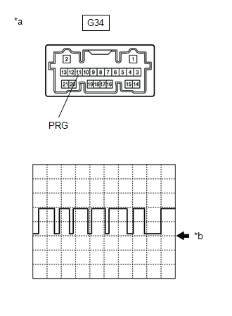
1. | INSPECT MAIN BODY ECU (MULTIPLEX NETWORK BODY ECU) (OUTPUT WAVEFORM) |
| (a) Using an oscilloscope, check the waveform. NOTICE: With the connector connected, check from the backside of the connector. Standard Voltage:
|
|
|
Result | Proceed to |
|---|---|
|
Waveform is as shown in the illustration. (Waveform alternates between 9.8 V or higher and 1.2 V or less) |
A |
| Waveform does not change from 9.8 V or higher |
B |
| Waveform does not change from 1.2 V or less |
C |
| A |
 | REPLACE TIRE PRESSURE WARNING ECU AND RECEIVER |
| B |
| REPLACE MAIN BODY ECU (MULTIPLEX NETWORK BODY ECU) |
|
| 2. |
CHECK TERMINAL VOLTAGE (TIRE PRESSURE WARNING ECU AND RECEIVER OUTPUT) |
(a) Disconnect the G34 main body ECU (multiplex network body ECU) connector.
(b) Measure the voltage according to the value(s) in the table below.
Standard Voltage:
|
Tester Connection | Condition |
Specified Condition |
|---|---|---|
|
G34-11 (PRG) - Body ground |
Engine switch on (IG) |
9.8 V or higher |
| OK | | REPLACE MAIN BODY ECU (MULTIPLEX NETWORK BODY ECU) |
|
| 3. |
CHECK HARNESS AND CONNECTOR (TIRE PRESSURE WARNING ECU AND RECEIVER - MAIN BODY ECU (MULTIPLEX NETWORK BODY ECU)) |
(a) Turn the engine switch off.
(b) Disconnect the K11 tire pressure warning ECU and receiver connector.
(c) Measure the resistance according to the value(s) in the table below.
Standard Resistance:
|
Tester Connection | Condition |
Specified Condition |
|---|---|---|
|
K11-5 (PRG) - G34-11 (PRG) |
Always | Below 1 Ω |
|
K11-5 (PRG) or G34-11 (PRG) - Body ground |
Always | 10 kΩ or higher |
| NG | | REPAIR OR REPLACE HARNESS OR CONNECTOR |
|
| 4. |
CHECK HARNESS AND CONNECTOR (POWER SUPPLY - TIRE PRESSURE WARNING ECU AND RECEIVER) |
(a) Measure the voltage according to the value(s) in the table below.
Standard Voltage:
|
Tester Connection | Condition |
Specified Condition |
|---|---|---|
|
K11-7 (+B) - Body ground |
Always | 10 to 16 V |
|
K11-1 (IG) - Body ground |
Engine switch on (IG) |
10 to 16 V |
| OK | | REPLACE TIRE PRESSURE WARNING ECU AND RECEIVER |
| NG | | REPAIR OR REPLACE HARNESS OR CONNECTOR |
DESCRIPTION
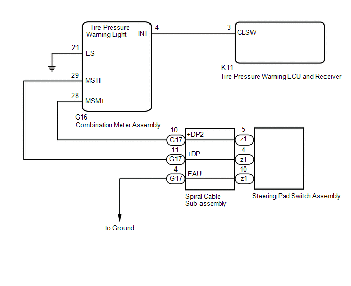
The switch circuit inside the combination meter assembly turns on and off according to the steering pad switch assembly operation.
During test mode, the tire pressure warning light blinks at 0.125 second intervals when "Set Pressure" is selected on the multi-information display, and illuminates when the "OK" switch (steering pad switch assembly) is pressed.
|
DTC No. | Detection Item |
DTC Detection Condition | Trouble Area |
Note |
|---|---|---|---|---|
| C2198 |
Initialization Switch Error (for Test Diagnosis) |
Test mode procedure is performed. |
| - |
WIRING DIAGRAM

CAUTION / NOTICE / HINT
NOTICE:
 after registration
of the transmitter IDs into the tire pressure warning ECU and receiver if the ECU has been replaced.
after registration
of the transmitter IDs into the tire pressure warning ECU and receiver if the ECU has been replaced.
PROCEDURE
|
1. | INSPECT STEERING PAD SWITCH ASSEMBLY |
(a) Remove the steering pad switch assembly.
Click here
(b) Inspect the steering pad switch assembly.
Click here
| NG |  | REPLACE STEERING PAD SWITCH ASSEMBLY |
|
| 2. |
INSPECT SPIRAL CABLE SUB-ASSEMBLY |
(a) Remove the spiral cable sub-assembly.
Click here
(b) Inspect the spiral cable sub-assembly.
Click here
| NG | | REPLACE SPIRAL CABLE SUB-ASSEMBLY |
|
| 3. |
CHECK HARNESS AND CONNECTOR (SPIRAL CABLE SUB-ASSEMBLY - COMBINATION METER ASSEMBLY) |
(a) Disconnect the G17 spiral cable sub-assembly connector.
(b) Disconnect the G16 combination meter assembly connector.
(c) Measure the resistance according to the value(s) in the table below.
Standard Resistance:
|
Tester Connection | Condition |
Specified Condition |
|---|---|---|
|
G17-10 (+DP2) - G16-28 (MSM+) |
Always | Below 1 Ω |
|
G17-10 (+DP2) or G16-28 (MSM+) - Body ground |
Always | 10 kΩ or higher |
|
G17-11 (+DP) - G16-29 (MSTI) |
Always | Below 1 Ω |
|
G17-11 (+DP) or G16-29 (MSTI) - Body ground |
Always | 10 kΩ or higher |
| NG | | REPAIR OR REPLACE HARNESS OR CONNECTOR |
|
| 4. |
CHECK HARNESS AND CONNECTOR (COMBINATION METER ASSEMBLY - TIRE PRESSURE WARNING ECU AND RECEIVER) |
(a) Disconnect the K11 tire pressure warning ECU and receiver connector.
(b) Disconnect the G16 combination meter assembly connector.
(c) Measure the resistance according to the value(s) in the table below.
Standard Resistance:
|
Tester Connection | Condition |
Specified Condition |
|---|---|---|
|
K11-3 (CLSW) - G16-4 (INT) |
Always | Below 1 Ω |
|
K11-3 (CLSW) or G16-4 (INT) - Body ground |
Always | 10 kΩ or higher |
|
G16-21 (ES) - Body ground |
Always | Below 1 Ω |
| NG | | REPAIR OR REPLACE HARNESS OR CONNECTOR |
|
| 5. |
CHECK TERMINAL VOLTAGE (INT) |
(a) Connect the K11 tire pressure warning ECU and receiver connector.
(b) Disconnect the G16 combination meter assembly connector.
(c) Measure the voltage according to the value(s) in the table below.
Standard Voltage:
|
Tester Connection | Condition |
Specified Condition |
|---|---|---|
|
G16-4 (INT) - Body ground |
Engine switch on (IG) |
8 to 15 V |
| OK | | GO TO METER / GAUGE SYSTEM |
| NG | | REPLACE TIRE PRESSURE WARNING ECU AND RECEIVER |
DESCRIPTION
When "Change Wheel" is selected on the multi-information display and the "OK" switch (steering pad switch assembly) is pushed and held, the system enters ID registration mode and the tire pressure warning light blinks 3 times.
The main body ECU (multiplex network body ECU) receives signals from the combination meter assembly via the CAN communication line.
WIRING DIAGRAM
PROCEDURE
| 1. |
CHECK TEST MODE (TIRE PRESSURE WARNING RESET SWITCH CHECK [DTC C2198]) |
(a) Perform Test Mode Procedure (Tire Pressure Warning Reset Switch Check (DTC C2198)).
Click here 
| NEXT |  | GO TO DTC C2198 |
DATA LIST / ACTIVE TEST
READ DATA LIST
HINT:
Using the Techstream to read the Data List allows the values or states of switches, sensors, actuators and other items to be read without removing any parts. This non-intrusive inspection can be very useful because intermittent conditions or signals may be discovered before parts or wiring is disturbed. Reading the Data List information early in troubleshooting is one way to save diagnostic time.
NOTICE:
In the table below, the values listed under "Normal Condition" are reference values. Do not depend solely on these reference values when deciding whether a part is faulty or not.
(a) Turn the engine switch off.
(b) Connect the Techstream to the DLC3.
(c) Turn the engine switch on (IG).
(d) Turn the Techstream on.
(e) Enter the following menus: Chassis / Tire Pressure Monitor / Data List.
(f) According to the display on the Techstream, read the Data List.
Chassis > Tire Pressure Monitor > Data List|
Tester Display | Measurement Item |
Range | Normal Condition |
Diagnostic Note |
|---|---|---|---|---|
|
Mode Status | Tire pressure warning system mode |
NORMAL or TEST | NORMAL: Normal mode TEST: Test mode | - |
|
Main Tire | Number of main tire ID to be registered |
4 or 5 | 4 displayed |
- |
| 2nd Tire |
Number of 2nd tire ID to be registered |
4 or 5 | 4 displayed |
- |
| Initialization Switch |
Tire pressure warning reset switch |
OFF or ON | OFF: "OK" switch (steering pad switch assembly) off ON: Steering pad switch assembly operated, "Set Pressure" selected on the multi-information display and "OK" switch (steering pad switch assembly) pressed and held | - |
|
Sensor ID Status | Status of ID selection |
Main or 2nd | Status of ID selection |
- |
| Initialization Switch Info |
Tire pressure warning reset switch setting information |
WITHOUT or WITH | WITH |
- |
| Initialization SW Function Information |
Tire pressure warning reset switch function information |
No Function, Auto Registered Function or Select Function |
Auto Registered Function |
- |
| Vehicle Speed |
Vehicle speed reading | min.: 0 km/h (0 mph) max.: 255 km/h (158 mph) |
Actual vehicle speed | Speed indicated on the combination meter assembly |
|
Registered ID 1 Code | Registered ID1 code |
min.: 0 max.: FFFFFFF*1 |
ID No. registered for transmitter ID1 displayed |
- |
| Registered ID 2 Code |
Registered ID2 code | min.: 0 max.: FFFFFFF*1 | ID No. registered for transmitter ID2 displayed |
- |
| Registered ID 3 Code |
Registered ID3 code | min.: 0 max.: FFFFFFF*1 | ID No. registered for transmitter ID3 displayed |
- |
| Registered ID 4 Code |
Registered ID4 code | min.: 0 max.: FFFFFFF*1 | ID No. registered for transmitter ID4 displayed |
- |
| Registered ID 5 Code |
Registered ID5 code | min.: 0 max.: FFFFFFF*1 | ID No. registered for transmitter ID5 displayed |
*3 |
| ID 1 Tire Inflation Pressure |
ID1 tire inflation pressure |
min.: Absolute pressure (abs) / 0 kPa (0 kgf/cm2, 0 psi), Relative pressure (Gauge) / 0 kPa (0 kgf/cm2, 0 psi) max.: Absolute pressure (abs) / 480 kPa (4.9 kgf/cm2, 70 psi), Relative pressure (Gauge) / 380 kPa (3.9 kgf/cm2, 55 psi) |
Actual tire inflation pressure |
If N/A is displayed, data has not been received.*2 |
|
ID 2 Tire Inflation Pressure |
ID2 tire inflation pressure |
min.: Absolute pressure (abs) / 0 kPa (0 kgf/cm2, 0 psi), Relative pressure (Gauge) / 0 kPa (0 kgf/cm2, 0 psi) max.: Absolute pressure (abs) / 480 kPa (4.9 kgf/cm2, 70 psi), Relative pressure (Gauge) / 380 kPa (3.9 kgf/cm2, 55 psi) |
Actual tire inflation pressure |
If N/A is displayed, data has not been received.*2 |
|
ID 3 Tire Inflation Pressure |
ID3 tire inflation pressure |
min.: Absolute pressure (abs) / 0 kPa (0 kgf/cm2, 0 psi), Relative pressure (Gauge) / 0 kPa (0 kgf/cm2, 0 psi) max.: Absolute pressure (abs) / 480 kPa (4.9 kgf/cm2, 70 psi), Relative pressure (Gauge) / 380 kPa (3.9 kgf/cm2, 55 psi) |
Actual tire inflation pressure |
If N/A is displayed, data has not been received.*2 |
|
ID 4 Tire Inflation Pressure |
ID4 tire inflation pressure |
min.: Absolute pressure (abs) / 0 kPa (0 kgf/cm2, 0 psi), Relative pressure (Gauge) / 0 kPa (0 kgf/cm2, 0 psi) max.: Absolute pressure (abs) / 480 kPa (4.9 kgf/cm2, 70 psi), Relative pressure (Gauge) / 380 kPa (3.9 kgf/cm2, 55 psi) |
Actual tire inflation pressure |
If N/A is displayed, data has not been received.*2 |
|
ID 5 Tire Inflation Pressure |
ID5 tire inflation pressure |
min.: Absolute pressure (abs) / 0 kPa (0 kgf/cm2, 0 psi), Relative pressure (Gauge) / 0 kPa (0 kgf/cm2, 0 psi) max.: Absolute pressure (abs) / 480 kPa (4.9 kgf/cm2, 70 psi), Relative pressure (Gauge) / 380 kPa (3.9 kgf/cm2, 55 psi) |
Actual tire inflation pressure |
|
| Threshold of Low-pressure (Lower Limit) |
Tire inflation pressure |
min.: Absolute pressure (abs) / 0 kPa (0 kgf/cm2, 0 psi), Relative pressure (Gauge) / 0 kPa (0 kgf/cm2, 0 psi) max.: Absolute pressure (abs) / 480 kPa (4.9 kgf/cm2, 70 psi), Relative pressure (Gauge) / 380 kPa (3.9 kgf/cm2, 55 psi) |
Specified tire pressure warning threshold lower limit displayed |
If N/A is displayed, data has not been received.*2 |
|
ID 1 Initial Threshold of Low-pressure |
ID1 initial threshold of low-pressure |
min.: Absolute pressure (abs) / 0 kPa (0 kgf/cm2, 0 psi), Relative pressure (Gauge) / 0 kPa (0 kgf/cm2, 0 psi) max.: Absolute pressure (abs) / 480 kPa (4.9 kgf/cm2, 70 psi), Relative pressure (Gauge) / 380 kPa (3.9 kgf/cm2, 55 psi) |
Tire pressure after initialization |
- |
| ID 2 Initial Threshold of Low-pressure |
ID2 initial threshold of low-pressure |
min.: Absolute pressure (abs) / 0 kPa (0 kgf/cm2, 0 psi), Relative pressure (Gauge) / 0 kPa (0 kgf/cm2, 0 psi) max.: Absolute pressure (abs) / 480 kPa (4.9 kgf/cm2, 70 psi), Relative pressure (Gauge) / 380 kPa (3.9 kgf/cm2, 55 psi) |
Tire pressure after initialization |
- |
| ID 3 Initial Threshold of Low-pressure |
ID3 initial threshold of low-pressure |
min.: Absolute pressure (abs) / 0 kPa (0 kgf/cm2, 0 psi), Relative pressure (Gauge) / 0 kPa (0 kgf/cm2, 0 psi) max.: Absolute pressure (abs) / 480 kPa (4.9 kgf/cm2, 70 psi), Relative pressure (Gauge) / 380 kPa (3.9 kgf/cm2, 55 psi) |
Tire pressure after initialization |
- |
| ID 4 Initial Threshold of Low-pressure |
ID4 initial threshold of low-pressure |
min.: Absolute pressure (abs) / 0 kPa (0 kgf/cm2, 0 psi), Relative pressure (Gauge) / 0 kPa (0 kgf/cm2, 0 psi) max.: Absolute pressure (abs) / 480 kPa (4.9 kgf/cm2, 70 psi), Relative pressure (Gauge) / 380 kPa (3.9 kgf/cm2, 55 psi) |
Tire pressure after initialization |
- |
| ID 5 Initial Threshold of Low-pressure |
ID5 initial threshold of low-pressure |
min.: Absolute pressure (abs) / 0 kPa (0 kgf/cm2, 0 psi), Relative pressure (Gauge) / 0 kPa (0 kgf/cm2, 0 psi) max.: Absolute pressure (abs) / 480 kPa (4.9 kgf/cm2, 70 psi), Relative pressure (Gauge) / 380 kPa (3.9 kgf/cm2, 55 psi) |
Tire pressure after initialization |
*3 |
| ID 1 Temperature in Tire |
ID1 temperature in tire |
min.: -40°C (-40°F) max.: 120°C (248°F) |
Actual tire temperature |
If -40°C (-40°F) is displayed, data has not been received. |
|
ID 2 Temperature in Tire |
ID2 temperature in tire |
min.: -40°C (-40°F) max.: 120°C (248°F) |
Actual tire temperature |
If -40°C (-40°F) is displayed, data has not been received. |
|
ID 3 Temperature in Tire |
ID3 temperature in tire |
min.: -40°C (-40°F) max.: 120°C (248°F) |
Actual tire temperature |
If -40°C (-40°F) is displayed, data has not been received. |
|
ID 4 Temperature in Tire |
ID4 temperature in tire |
min.: -40°C (-40°F) max.: 120°C (248°F) |
Actual tire temperature |
If -40°C (-40°F) is displayed, data has not been received. |
|
ID 5 Temperature in Tire |
ID5 temperature in tire |
min.: -40°C (-40°F) max.: 120°C (248°F) |
Actual tire temperature |
|
| ID 1 Tire Position |
ID1 Tire Position | No Information or FL or FR or RL or RR or Spare or Judging |
ID1 tire position is displayed |
If no tire position information is stored, "No Information" will be displayed. |
|
ID 2 Tire Position | ID2 Tire Position |
No Information or FL or FR or RL or RR or Spare or Judging |
ID1 tire position is displayed |
If no tire position information is stored, "No Information" will be displayed. |
|
ID 3 Tire Position | ID3 Tire Position |
No Information or FL or FR or RL or RR or Spare or Judging |
ID1 tire position is displayed |
If no tire position information is stored, "No Information" will be displayed. |
|
ID 4 Tire Position | ID4 Tire Position |
No Information or FL or FR or RL or RR or Spare or Judging |
ID1 tire position is displayed |
If no tire position information is stored, "No Information" will be displayed. |
|
ID 5 Tire Position | ID5 Tire Position |
No Information or FL or FR or RL or RR or Spare or Judging |
ID1 tire position is displayed |
|
| ID 1 - FL Wheel Speed Synchronization Count |
ID1 - FL Wheel Speed Synchronization Count |
min.: 0, max.: 255 | Actual Synchronization Count |
- |
| ID 1 - FR Wheel Speed Synchronization Count |
ID1 - FR Wheel Speed Synchronization Count |
min.: 0, max.: 255 | Actual Synchronization Count |
- |
| ID 1 - RL Wheel Speed Synchronization Count |
ID1 - RL Wheel Speed Synchronization Count |
min.: 0, max.: 255 | Actual Synchronization Count |
- |
| ID 1 - RR Wheel Speed Synchronization Count |
ID1 - RR Wheel Speed Synchronization Count |
min.: 0, max.: 255 | Actual Synchronization Count |
- |
| ID 2 - FL Wheel Speed Synchronization Count |
ID2 - FL Wheel Speed Synchronization Count |
min.: 0, max.: 255 | Actual Synchronization Count |
- |
| ID 2 - FR Wheel Speed Synchronization Count |
ID2 - FR Wheel Speed Synchronization Count |
min.: 0, max.: 255 | Actual Synchronization Count |
- |
| ID 2 - RL Wheel Speed Synchronization Count |
ID2 - RL Wheel Speed Synchronization Count |
min.: 0, max.: 255 | Actual Synchronization Count |
- |
| ID 2 - RR Wheel Speed Synchronization Count |
ID2 - RR Wheel Speed Synchronization Count |
min.: 0, max.: 255 | Actual Synchronization Count |
- |
| ID 3 - FL Wheel Speed Synchronization Count |
ID3 - FL Wheel Speed Synchronization Count |
min.: 0, max.: 255 | Actual Synchronization Count |
- |
| ID 3 - FR Wheel Speed Synchronization Count |
ID3 - FR Wheel Speed Synchronization Count |
min.: 0, max.: 255 | Actual Synchronization Count |
- |
| ID 3 - RL Wheel Speed Synchronization Count |
ID3 - RL Wheel Speed Synchronization Count |
min.: 0, max.: 255 | Actual Synchronization Count |
- |
| ID 3 - RR Wheel Speed Synchronization Count |
ID3 - RR Wheel Speed Synchronization Count |
min.: 0, max.: 255 | Actual Synchronization Count |
- |
| ID 4 - FL Wheel Speed Synchronization Count |
ID4 - FL Wheel Speed Synchronization Count |
min.: 0, max.: 255 | Actual Synchronization Count |
- |
| ID 4 - FR Wheel Speed Synchronization Count |
ID4 - FR Wheel Speed Synchronization Count |
min.: 0, max.: 255 | Actual Synchronization Count |
- |
| ID 4 - RL Wheel Speed Synchronization Count |
ID4 - RL Wheel Speed Synchronization Count |
min.: 0, max.: 255 | Actual Synchronization Count |
- |
| ID 4 - RR Wheel Speed Synchronization Count |
ID4 - RR Wheel Speed Synchronization Count |
min.: 0, max.: 255 | Actual Synchronization Count |
- |
| ID 5 - FL Wheel Speed Synchronization Count |
ID5 - FL Wheel Speed Synchronization Count |
min.: 0, max.: 255 | Actual Synchronization Count |
*3 |
| ID 5 - FR Wheel Speed Synchronization Count |
ID5 - FR Wheel Speed Synchronization Count |
min.: 0, max.: 255 | Actual Synchronization Count |
*3 |
| ID 5 - RL Wheel Speed Synchronization Count |
ID5 - RL Wheel Speed Synchronization Count |
min.: 0, max.: 255 | Actual Synchronization Count |
*3 |
| ID 5 - RR Wheel Speed Synchronization Count |
ID5 - RR Wheel Speed Synchronization Count |
min.: 0, max.: 255 | Actual Synchronization Count |
*3 |
| Last Time ID Registered mode |
Method for registering currently registered ID |
Manual ID Registered, Not Registered or Auto ID Registered |
Displays method for registering currently registered ID |
- |
| [FLASH] Auto ID Registered FL Wheel Judgment Status |
FL wheel registration status during automatic ID registration (FLASH) |
Fixed, Under a Judgment of Side by Side Car Influence or Under a Judgment, Not Registered |
Actual registration status |
Driving distance is updated and recorded every 10 minutes |
|
[FLASH] Auto ID Registered FR Wheel Judgment Status |
FR wheel registration status during automatic ID registration (FLASH) |
Fixed, Under a Judgment of Side by Side Car Influence or Under a Judgment, Not Registered |
Actual registration status |
Driving distance is updated and recorded every 10 minutes |
|
[FLASH] Auto ID Registered RL Wheel Judgment Status |
RL wheel registration status during automatic ID registration (FLASH) |
Fixed, Under a Judgment of Side by Side Car Influence or Under a Judgment, Not Registered |
Actual registration status |
Driving distance is updated and recorded every 10 minutes |
|
[FLASH] Auto ID Registered RR Wheel Judgment Status |
RR wheel registration status during automatic ID registration (FLASH) |
Fixed, Under a Judgment of Side by Side Car Influence or Under a Judgment, Not Registered |
Actual registration status |
Driving distance is updated and recorded every 10 minutes |
|
[FLASH] Auto ID Registered Spare Wheel Judgment Status |
Spare wheel registration status during automatic ID registration (FLASH) |
Fixed, Under a Judgment of Side by Side Car Influence or Under a Judgment, Not Registered |
Actual registration status |
|
| [RAM] Auto ID Registered FL Wheel Judgment Status |
FL wheel registration status during automatic ID registration (RAM) |
Fixed, Under a Judgment of Side by Side Car Influence or Under a Judgment, Not Registered |
Actual registration status |
Cleared each time the engine switch is turned on (IG) from off. |
|
[RAM] Auto ID Registered FR Wheel Judgment Status |
FR wheel registration status during automatic ID registration (RAM) |
Fixed, Under a Judgment of Side by Side Car Influence or Under a Judgment, Not Registered |
Actual registration status |
Cleared each time the engine switch is turned on (IG) from off. |
|
[RAM] Auto ID Registered RL Wheel Judgment Status |
RL wheel registration status during automatic ID registration (RAM) |
Fixed, Under a Judgment of Side by Side Car Influence or Under a Judgment, Not Registered |
Actual registration status |
Cleared each time the engine switch is turned on (IG) from off. |
|
[RAM] Auto ID Registered RR Wheel Judgment Status |
RR wheel registration status during automatic ID registration (RAM) |
Fixed, Under a Judgment of Side by Side Car Influence or Under a Judgment, Not Registered |
Actual registration status |
Cleared each time the engine switch is turned on (IG) from off. |
|
[RAM] Auto ID Registered Spare Wheel Judgment Status |
Spare wheel registration status during automatic ID registration (RAM) |
Fixed, Under a Judgment of Side by Side Car Influence or Under a Judgment, Not Registered |
Actual registration status |
|
| Number of Trouble Code |
Number of stored DTCs | min.: 0 max.: 255 | min.: 0 max.: - | - |
HINT:
Click here 
PERFORM ACTIVE TEST
Using the Techstream to perform Active Tests allows the relays, VSVs, actuators and other items to be operated without removing any parts. This non-intrusive functional inspection can be very useful because intermittent operation may be discovered before parts or wiring is disturbed. Performing Active Tests early in troubleshooting is one way to save diagnostic time. Data List information can be displayed while performing Active Tests.
(a) Turn the engine switch off.
(b) Connect the Techstream to the DLC3.
(c) Turn the engine switch on (IG).
(d) Turn the Techstream on.
(e) Enter the following menus: Body Electrical / Combination Meter / Active Test.
(f) Perform the Active Test according to the display on the Techstream.
Body Electrical > Combination Meter > Active Test|
Tester Display | Measurement Item |
Control Range | Diagnostic Note |
|---|---|---|---|
|
Tire Pressure Warning System Indicator |
Tire pressure warning light |
OFF or ON | - |
DIAGNOSIS SYSTEM
CHECK WARNING LIGHT
NOTICE:
Click here 
(a) Turn the engine switch on (IG).
|
*1 | Tire Pressure Warning Light |
(b) Check that the tire pressure warning light illuminates for 3 seconds.
WHAT TO CONSIDER WHEN TIRE PRESSURE WARNING LIGHT ILLUMINATES
(a) When the tire pressure warning light does not go off, or when it illuminates during driving, check the tire pressure. If the tire pressure warning light illuminates within several hours after adjusting the tire pressure, a tire may have a slow air leak.
(b) The system is disabled under the following conditions (when the condition returns to normal, the system will work properly).
(1) When all of the tire and wheel assemblies that have tire pressure warning valve and transmitters registered with the tire pressure warning ECU and receiver have not been installed.
(2) When all of the transmitter ID codes are not registered with the tire pressure warning ECU and receiver.
(3) When the tire pressure warning valve and transmitter battery is depleted (Battery life is 10 years).
(c) The system may become disabled under the following conditions (when the condition returns to normal, the system will work properly).
(1) When electric devices or facilities using similar radio frequencies are nearby.
(2) When a wireless device or other equipment operating at a similar frequency is in use in the vehicle.
(3) When a window tint that affects radio wave signals is installed.
(4) When there is a lot of snow or ice on the vehicle, in particular, around the wheels or wheel housing.
(5) When non-genuine wheels are used.
(6) When tire chains are used.
(7) When aftermarket tire repair sealant is used.
CAUTION:
After use of tire repair sealant, replacement of the tire pressure warning valve and transmitter is required to ensure normal system operation. (Normal system operation cannot be ensured by only repairing or replacing the tire.)
TIRE PRESSURE WARNING LIGHT AND INDICATOR CHART
HINT:
The table below indicates the state of the tire pressure warning light after the engine switch is turned on (IG).
|
Immediately after turning the engine switch on (IG) |
Always | |||||
|---|---|---|---|---|---|---|
|
Warning light output pattern |
Multi-information Display Condition | |||||
|
Illuminates for 3 sec. |
Illuminates for 4 sec. |
Goes off | Illuminates |
Blinks | Displays | |
|
Normal | ○ |
- | ○ |
- | - |
- |
| Low tire pressure |
○ | - |
- | ○ |
- | Tire Pressure Low Check Tire |
|
System failure | ○ |
- | - |
- | *1 |
TPWS Malfunction Visit Your Dealer HINT:
|
| Test mode (signal check mode) |
○ | - |
- | - |
*2 | - |
|
Tire pressure initialization |
- | ○ |
○ | - |
*3 | Setting Tire Pressure Warning System |
|
Tire position identification in progress |
○ | - |
○ | - |
- | - |
|
ECU connector poorly connected |
- | - |
- | - |
*4 | - |
|
ID certification, automatic ID registration |
○ | - |
- | - |
*1 | Tire Pressure Recalibrating Please Wait until Complete |
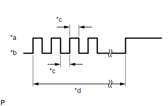
|
*a |
ON |
|
*b |
OFF |
|
*c |
0.5 sec. |
|
*d |
1 minute |
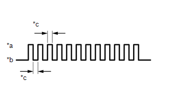
|
*a |
ON |
|
*b |
OFF |
|
*c |
0.125 sec. |
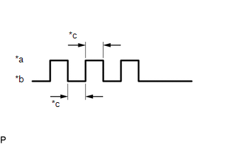
|
*a |
ON |
|
*b |
OFF |
|
*c |
1 sec. |
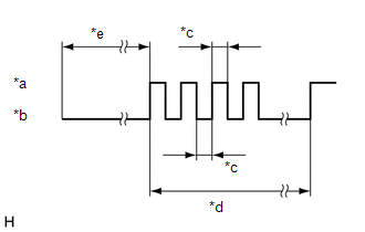
|
*a |
ON |
|
*b |
OFF |
|
*c |
0.5 sec. |
|
*d |
1 minute |
|
*e |
10 sec. |
NORMAL MODE DTC
(a) DTCs are stored in the tire pressure warning ECU and receiver and output by blinking the tire pressure warning light or by using the Techstream.
Click here
TEST MODE (SIGNAL CHECK MODE) DTC
(a) By switching from normal mode into test mode (signal check mode), the tire pressure warning ECU and receiver, each tire pressure warning valve and transmitter and tire pressure warning reset switch can be inspected.
Click here
DIAGNOSTIC TROUBLE CODE CHART
Tire Pressure Warning ECU and Receiver|
DTC No. | Detection Item |
Note | Link |
|---|---|---|---|
|
B1247 | Tire Pressure Monitor Receiver Communication Stop |
This DTC is for main body ECU (multiplex network body ECU) |
|
|
C2111 | Transmitter ID1 Operation Stop |
- |
|
|
C2112 | Transmitter ID2 Operation Stop |
- |
|
|
C2113 | Transmitter ID3 Operation Stop |
- |
|
|
C2114 | Transmitter ID4 Operation Stop |
- |
|
|
C2121 | Transmitter ID 1 not Received (Main) |
- |
|
|
C2122 | Transmitter ID 2 not Received (Main) |
- |
|
|
C2123 | Transmitter ID 3 not Received (Main) |
- |
|
|
C2124 | Transmitter ID 4 not Received (Main) |
- |
|
|
C2126 | Transmitter ID not Received (Main) |
- |
|
|
C2128 | Auto ID Under Registration |
- |
|
|
C2141 | Transmitter ID1 Error |
- |
|
|
C2142 | Transmitter ID2 Error |
- |
|
|
C2143 | Transmitter ID3 Error |
- |
|
|
C2144 | Transmitter ID4 Error |
- |
|
|
C2171 | Transmitter ID not Registered (Main) |
- |
|
|
C2176 | Receiver Error |
- |
|
|
C2177 | Initialization not Completed |
- |
|
|
C2178 | Vehicle Speed Information Communication Lost |
- |
|
|
C2179 | Tire Pressure Monitor ECU Communication Stop |
- |
|
|
C2181 | Transmitter ID 1 not Received (for Test Diagnosis) |
- |
|
|
C2182 | Transmitter ID 2 not Received (for Test Diagnosis) |
- |
|
|
C2183 | Transmitter ID 3 not Received (for Test Diagnosis) |
- |
|
|
C2184 | Transmitter ID 4 not Received (for Test Diagnosis) |
- |
|
|
C2198 | Initialization Switch Error (for Test Diagnosis) |
- |
|
|
U0129 | Lost Communication with Brake System Control Module |
- |
|
DTC CHECK / CLEAR
CHECK DTC (for TIRE PRESSURE WARNING ECU AND RECEIVER)
(a) Turn the engine switch off.
(b) Connect the Techstream to the DLC3.
(c) Turn the engine switch on (IG).
(d) Turn the Techstream on.
(e) Enter the following menus: Chassis / Tire Pressure Monitor / Trouble Codes.
Chassis > Tire Pressure Monitor > Trouble Codes(f) Read the DTCs.
CHECK DTC (for MAIN BODY ECU (MULTIPLEX NETWORK BODY ECU))
(a) Turn the engine switch off.
(b) Connect the Techstream to the DLC3.
(c) Turn the engine switch on (IG).
(d) Turn the Techstream on.
(e) Enter the following menus: Body Electrical / Main Body / Trouble Codes.
Body Electrical > Main Body > Trouble Codes(f) Read the DTCs.
CLEAR DTC (for TIRE PRESSURE WARNING ECU AND RECEIVER)
HINT:
After repairing the malfunctions, clear the DTCs.
(a) Turn the engine switch off.
(b) Connect the Techstream to the DLC3.
(c) Turn the engine switch on (IG).
(d) Turn the Techstream on.
(e) Enter the following menus: Chassis / Tire Pressure Monitor / Trouble Codes.
Chassis > Tire Pressure Monitor > Clear DTCs(f) Clear the DTCs following the prompts on the Techstream screen.
HINT:
Refer to the Techstream operator's manual for further details.
CLEAR DTC (for MAIN BODY ECU (MULTIPLEX NETWORK BODY ECU))
HINT:
After repairing the malfunctions, clear the DTCs.
(a) Turn the engine switch off.
(b) Connect the Techstream to the DLC3.
(c) Turn the engine switch on (IG).
(d) Turn the Techstream on.
(e) Enter the following menus: Body Electrical / Main Body / Trouble Codes.
Body Electrical > Main Body > Clear DTCs(f) Clear the DTCs following the prompts on the Techstream screen.
HINT:
Refer to the Techstream operator's manual for further details.
FAIL-SAFE CHART
FAIL-SAFE FUNCTION
(a) When a malfunction occurs in the tire pressure warning system, the tire pressure warning light illuminates after blinking for 1 minute to inform the driver of the system failure.
(b) As a result of this, tire pressure monitoring is disabled and a DTC is stored in the tire pressure warning ECU and receiver.
(c) When there is a system malfunction, the value of each related tire is not displayed.
|
*a | Example |
CAUTION / NOTICE / HINT
HINT:
PROCEDURE
|
1. | VEHICLE BROUGHT TO WORKSHOP |
|
| 2. |
CUSTOMER PROBLEM ANALYSIS |
(a) Interview the customer to confirm the problem.
HINT:
It is important to collect as much specific information as possible from the customer to allow for a quick repair.
|
| 3. |
ADJUST TIRE PRESSURE* |
(a) Turn the engine switch off.
(b) Connect the Techstream to the DLC3.
(c) Turn the engine switch on (IG).
(d) Turn the Techstream on.
(e) Enter the following menus: Chassis / Tire Pressure Monitor / Data List.
(f) Set all tire pressures to the specified value.
NOTICE:
Refer to the link as the procedure for adjusting the tire pressures differs depending on the temperature of the tires.
Click here 
(g) Display "ID Tire Inflation Pressure" in the Data List and check that the tire pressure values match the adjusted pressure amount.
HINT:
It may take a few minutes until the values are displayed.
(h) Perform initialization.
Click here
HINT:
The tire pressure warning system illuminates the tire pressure warning light to warn the driver when any of the following condition is met:
| Result |
Proceed to |
|---|---|
| Tire pressure warning light remains on |
A |
| Tire pressure warning light goes off |
B |
| B |
 | GO TO STEP 11 |
|
| 4. |
CHECK ECU CONNECTED TO CAN BUS* |
(a) Check the ECUs connected to the CAN bus.
Click here
| Result |
Proceed to |
|---|---|
| No malfunction appears |
A |
| Malfunction appears |
B |
| B |
| GO TO CAN COMMUNICATION SYSTEM |
|
| 5. |
CHECK FOR DTC (CAN COMMUNICATION SYSTEM)* |
(a) Check for DTCs.
Click here
| Result |
Proceed to |
|---|---|
| CAN system DTCs are not output |
A |
| CAN system DTCs are output |
B |
| B |
| GO TO CAN COMMUNICATION SYSTEM |
|
| 6. |
CHECK FOR DTC* |
(a) Check for DTCs.
Click here
| Result |
Proceed to |
|---|---|
| DTCs are output |
A |
| DTCs are not output |
B |
| B |
| GO TO STEP 8 |
|
| 7. |
DTC CHART |
(a) Refer to Diagnostic Trouble Code Chart.
Click here
| NEXT | | GO TO STEP 10 |
| 8. |
PROBLEM SYMPTOMS TABLE |
(a) Refer to Problem Symptoms Table.
Click here
|
| 9. |
CIRCUIT INSPECTION* |
(a) Refer to Electronic Circuit Inspection Procedure.
Click here
|
| 10. |
REPAIR OR REPLACE |
(a) Repair or replace parts based on the diagnosis result.
|
| 11. |
CONFIRMATION TEST* |
(a) Check the Data List to confirm that the tire inflation pressure has been received.
Click here
(b) Perform initialization.
Click here
(c) Confirm that the initialization has been completed.
| NEXT | | END |
INITIALIZATION
NOTICE:
Click here 
However, it may take 10 minutes or more until the tire pressure of the tire inflation pressure display function is shown (Tire Inflation Pressure Display Function).
Click here
BEFORE INITIALIZATION
(a) Set the tire pressure to the specified value.
NOTICE:
Refer to the link as the procedure for adjusting the tire pressures differs depending on the temperature of the tires.
Click here
HINT:
The tire pressure warning system illuminates the tire pressure warning light to warn the driver when any of the following condition is met:
INITIALIZATION PROCEDURE
(a) Turn the engine switch on (IG).
(b) Select "Set Pressure" on the multi-information display and press and hold the "OK" switch (steering pad switch assembly) until the tire pressure warning light blinks 3 times.
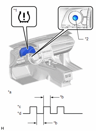
|
*1 | Tire Pressure Warning Light |
|
*2 | "OK" Switch (Steering Pad Switch Assembly) |
|
*a | Tire Pressure Warning Light Output Pattern |
|
*b | 1 sec. |
|
*c | ON |
|
*d | OFF |
(c) Turn the engine switch off.
(d) Connect the Techstream to the DLC3.
(e) Turn the engine switch on (IG).
(f) Turn the Techstream on.
(g) Enter the following menus: Chassis / Tire Pressure Monitor / Data List.
Chassis > Tire Pressure Monitor > Data List|
Tester Display | Measurement Item |
Range | Normal Condition |
Diagnostic Note |
|---|---|---|---|---|
|
ID 1 Tire Inflation Pressure |
ID1 tire inflation pressure |
min.: Absolute pressure (abs) / 0 kPa (0 kgf/cm2, 0 psi), Relative pressure (Gauge) / 0 kPa (0 kgf/cm2, 0 psi) max.: Absolute pressure (abs) / 480 kPa (4.9 kgf/cm2, 70 psi), Relative pressure (Gauge) / 380 kPa (3.9 kgf/cm2, 55 psi) |
Actual tire inflation pressure |
If N/A is displayed, data has not been received.*1 |
|
ID 2 Tire Inflation Pressure |
ID2 tire inflation pressure |
min.: Absolute pressure (abs) / 0 kPa (0 kgf/cm2, 0 psi), Relative pressure (Gauge) / 0 kPa (0 kgf/cm2, 0 psi) max.: Absolute pressure (abs) / 480 kPa (4.9 kgf/cm2, 70 psi), Relative pressure (Gauge) / 380 kPa (3.9 kgf/cm2, 55 psi) |
Actual tire inflation pressure |
If N/A is displayed, data has not been received.*1 |
|
ID 3 Tire Inflation Pressure |
ID3 tire inflation pressure |
min.: Absolute pressure (abs) / 0 kPa (0 kgf/cm2, 0 psi), Relative pressure (Gauge) / 0 kPa (0 kgf/cm2, 0 psi) max.: Absolute pressure (abs) / 480 kPa (4.9 kgf/cm2, 70 psi), Relative pressure (Gauge) / 380 kPa (3.9 kgf/cm2, 55 psi) |
Actual tire inflation pressure |
If N/A is displayed, data has not been received.*1 |
|
ID 4 Tire Inflation Pressure |
ID4 tire inflation pressure |
min.: Absolute pressure (abs) / 0 kPa (0 kgf/cm2, 0 psi), Relative pressure (Gauge) / 0 kPa (0 kgf/cm2, 0 psi) max.: Absolute pressure (abs) / 480 kPa (4.9 kgf/cm2, 70 psi), Relative pressure (Gauge) / 380 kPa (3.9 kgf/cm2, 55 psi) |
Actual tire inflation pressure |
If N/A is displayed, data has not been received.*1 |
HINT:
(h) Check that initialization has been completed.
(i) Confirm that the tire pressure data of all tires is displayed on the Techstream screen.
OPERATION CHECK
CHECK TIRE PRESSURE WARNING SYSTEM FUNCTION
(a) Using the Data List, check that the current tire pressure is normal.
Click here 
(1) Slowly reduce the tire pressure of the front or rear tires and check that the tire pressure on the Data List changes.
(2) Further reduce the tire pressure and check that the warning light illuminates.
(b) After reducing the tire pressure, set the tire pressure to the specified value.
Click here
PARTS LOCATION
ILLUSTRATION
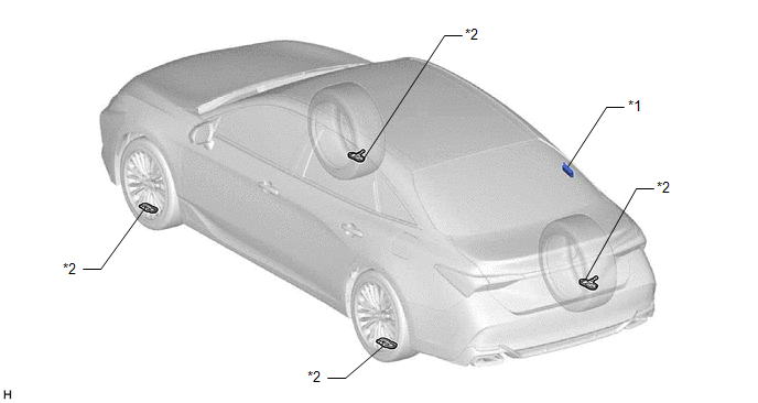
|
*1 | TIRE PRESSURE WARNING ECU AND RECEIVER |
*2 | TIRE PRESSURE WARNING VALVE AND TRANSMITTER |
ILLUSTRATION
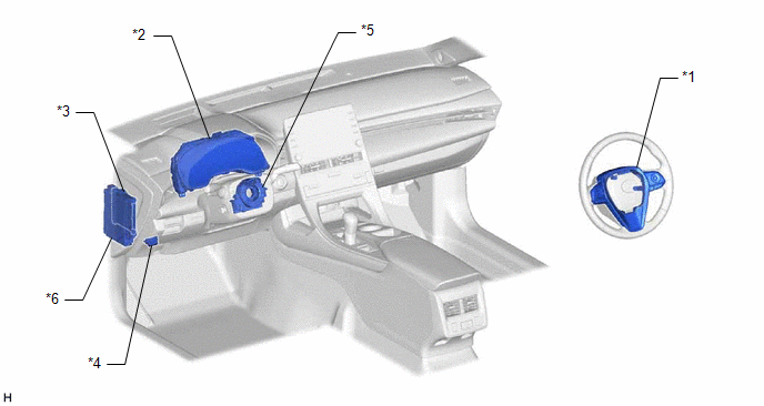
|
*1 | STEERING PAD SWITCH ASSEMBLY |
*2 | COMBINATION METER ASSEMBLY - TIRE PRESSURE WARNING LIGHT - MULTI-INFORMATION DISPLAY |
|
*3 | MAIN BODY ECU (MULTIPLEX NETWORK BODY ECU) |
*4 | DLC3 |
|
*5 | SPIRAL CABLE SUB-ASSEMBLY |
*6 | INSTRUMENT PANEL JUNCTION BLOCK ASSEMBLY - ECU-IG1 NO. 4 FUSE - ECU-B NO. 2 FUSE |
ILLUSTRATION
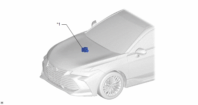
|
*1 | SKID CONTROL ECU (BRAKE ACTUATOR ASSEMBLY) |
- | - |
PRECAUTION
PRECAUTION FOR DISCONNECTING CABLE FROM NEGATIVE BATTERY TERMINAL
NOTICE:
When disconnecting the cable from the negative (-) battery terminal, initialize the following systems after the cable is reconnected.
|
System Name | See Procedure |
|---|---|
|
Lane Departure Alert System (w/ Steering Control) |
|
|
Intelligent Clearance Sonar System | |
|
Parking Assist Monitor System | |
|
Panoramic View Monitor System | |
|
Pre-collision System | |
| Lighting System (for Gasoline Model with Cornering Light) |
TIRE PRESSURE WARNING ECU AND RECEIVER EXPRESSIONS
(a) The electrical key and tire pressure monitoring system receiver assembly is referred to as the tire pressure warning ECU and receiver in this section.
TIRE PRESSURE WARNING SYSTEM PRECAUTION
(a) Tire pressure decreases naturally over time, which also occurs in vehicle models without a tire pressure warning system.
HINT:
Tire pressure decreases by approximately 5 kPa (0.05 kgf/cm2, 0.7 psi) to 10 kPa (0.1 kgf/cm2, 1.5 psi) per month.
(b) It is necessary for the tire pressures to be adjusted periodically.
(c) In winter, tire pressure may decrease due to low ambient temperatures (tire pressure decreases by approximately 10 kPa (0.1 kgf/cm2, 1.5 psi) for every 10°C (18°F) drop in the ambient temperature). Therefore, the tire pressure warning system is more likely to indicate a warning if the tire pressures are not adjusted appropriately. If the daily temperature variation is large, increase the pressure of the tires so that the tire pressures are suitable under cold conditions. As a result, unnecessary tire pressure warning operations should decrease.
(d) Depending on the tire type, the system may not function properly even if the specified wheels are used.
(e) To prevent damage to the tire pressure warning valve and transmitter, make sure that the tire pressure warning valve and transmitter does not interfere with the tire bead when installing or removing a tire.
(f) To prevent damage to the tire pressure warning valve and transmitter, before disengaging the tire bead or removing the tire from the wheel, drop the tire pressure warning valve and transmitter into the wheel.
(g) Always use a new grommet and valve core when installing a tire pressure warning valve and transmitter to ensure the sealing performance.
(h) When replacing the tire pressure warning valve and transmitter, all tire pressure warning valve and transmitter ID codes and the amount of tires with transmitters must be registered to the tire pressure warning ECU and receiver. Even when replacing only one of the tire pressure warning valve and transmitters, all tire pressure warning valve and transmitter ID codes and the amount of tires with transmitters must be re-registered.
Make sure to record the current ID codes and already registered tires with transmitters (4 or 5) before performing registration for new ID codes and tires with transmitters.
(i) Use only a specified cap. If an unspecified cap is used, it may seize to the tire pressure warning valve and transmitter.
(j) The system is disabled under the following conditions (when the condition returns to normal, the system will work properly).
(1) When all of the tire and wheel assemblies that have tire pressure warning valve and transmitters registered with the tire pressure warning ECU and receiver have not been installed.
(2) When all of the transmitter ID codes are not registered with the tire pressure warning ECU and receiver.
(3) When the tire pressure warning valve and transmitter battery is depleted (Battery life is 10 years).
(k) The system may become disabled under the following conditions (when the condition returns to normal, the system will work properly).
(1) When electric devices or facilities using similar radio frequencies are nearby.
(2) When a wireless device or other equipment operating at a similar frequency is in use in the vehicle.
(3) When a window tint that affects radio wave signals is installed.
(4) When there is a lot of snow or ice on the vehicle, in particular, around the wheels or wheel housing.
(5) When non-genuine wheels are used.
(6) When tire chains are used.
(7) When aftermarket tire repair sealant is used.
CAUTION:
After use of tire repair sealant, replacement of the tire pressure warning valve and transmitter is required to ensure normal system operation. (Normal system operation cannot be ensured by only repairing or replacing the tire.)
(l) Tire Inflation Pressure Display Function:
(1) The tire inflation pressure display function displays the position and pressure of each tire on the multi-information display. If the position and pressure of each tire are not displayed, the problem may be alleviated by driving the vehicle to a location where the signal reception is better.
NECESSARY PROCEDURES WHEN REPLACING PARTS
(a) ID Registration
When replacing the tire pressure warning valve and transmitter and tire pressure warning ECU and receiver, perform ID registration for the tire pressure warning valve and transmitter.
Click here

(b) Initialization
After performing ID registration for the tire pressure warning valve and transmitter, make sure to initialize the tire pressure warning system.
Click here
(c) Tire Inflation Pressure Display Function:
Tire Position Identification
After performing ID registration for the tire pressure warning valve and transmitter and initializing the tire pressure warning system, perform tire position identification.
Click here
PROBLEM SYMPTOMS TABLE
HINT:
|
Symptom | Suspected Area |
Link |
|---|---|---|
|
Tire pressure warning light does not illuminate despite tire pressure decreasing |
Initialization |
|
|
Check Data List (ID Tire Inflation Pressure) |
| |
|
ID code check (Registration) |
| |
|
Tire pressure warning light remains illuminated (Goes off during initial check) |
Tire pressure warning light circuit |
|
|
Tire pressure warning light remains illuminated (Illuminates during initial check) |
Check Data List (ID Tire Inflation Pressure) |
|
|
Tire pressure adjustment |
| |
|
ID code check (Registration) |
| |
|
Initialization |
| |
|
Initialization cannot be done |
Tire pressure warning reset switch |
|
|
Tire position not identified | Refer to "Tire position not identified". |
|
|
Cannot switch to automatic ID registration mode |
Refer to "Cannot switch to automatic ID registration mode". |
|
REGISTRATION
PROCEDURE
1. BEFORE REGISTRATION
NOTICE:
(a) When replacing the tire pressure warning ECU and receiver:
(1) When replacing the tire pressure warning ECU and receiver, read the transmitter IDs and number of the transmitters (4 or 5) stored in the old ECU using the Techstream and write them down before removal.
(2) If reading the stored transmitter IDs is impossible due to malfunctions of components such as the tire pressure warning ECU and receiver, remove the tires from the wheels and check the IDs located on the tire pressure warning valve and transmitters.
(b) When replacing a tire pressure warning valve and transmitter:
(1) Take a note of the 7-digit number (transmitter ID) written on the tire pressure warning valve and transmitter.
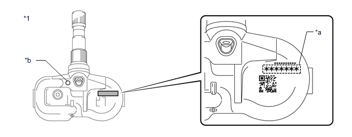
|
*1 | Tire Pressure Warning Valve and Transmitter |
- | - |
|
*a | Transmitter ID (7-digit Number) |
*b | Wheel Speed Type Tire Inflation Pressure Display Function Identification Mark |
NOTICE:
For vehicles equipped with the wheel speed type tire inflation pressure display function, be sure to use tire pressure warning valve and transmitters with identification marks.
2. REGISTER TRANSMITTER ID (USING TECHSTREAM)
HINT:
(a) Set the tire pressure to the specified value.
Click here

(b) Turn the engine switch off.
(c) Connect the Techstream to the DLC3.
(d) Turn the engine switch on (IG).
(e) Turn the Techstream on.
(f) Enter the following menus: Chassis / Tire Pressure Monitor / Utility / ID Registration/Tire Number Registration.
Chassis > Tire Pressure Monitor > Utility|
Tester Display |
|---|
| ID Registration/Tire Number Registration |
(g) Perform the procedure displayed on the Techstream.
HINT:
The number of registered tire pressure warning valve and transmitters can only be set to 4 when the value is currently set to 5. The number of registered tire pressure warning valve and transmitters should only be changed from the default value when requested by the customer.
3. CONFIRMATION OF TRANSMITTER ID REGISTRATION (USING TECHSTREAM)
NOTICE:
Click here
(a) Enter the following menus: Chassis / Tire Pressure Monitor / Data List.
Chassis > Tire Pressure Monitor > Data List|
Tester Display | Measurement Item |
Range | Normal Condition |
Diagnostic Note |
|---|---|---|---|---|
|
ID 1 Tire Inflation Pressure |
ID1 tire inflation pressure |
min.: Absolute pressure (abs) / 0 kPa (0 kgf/cm2, 0 psi), Relative pressure (Gauge) / 0 kPa (0 kgf/cm2, 0 psi) max.: Absolute pressure (abs) / 480 kPa (4.9 kgf/cm2, 70 psi), Relative pressure (Gauge) / 380 kPa (3.9 kgf/cm2, 55 psi) |
Actual tire inflation pressure |
If N/A is displayed, data has not been received.*1 |
|
ID 2 Tire Inflation Pressure |
ID2 tire inflation pressure |
min.: Absolute pressure (abs) / 0 kPa (0 kgf/cm2, 0 psi), Relative pressure (Gauge) / 0 kPa (0 kgf/cm2, 0 psi) max.: Absolute pressure (abs) / 480 kPa (4.9 kgf/cm2, 70 psi), Relative pressure (Gauge) / 380 kPa (3.9 kgf/cm2, 55 psi) |
Actual tire inflation pressure |
If N/A is displayed, data has not been received.*1 |
|
ID 3 Tire Inflation Pressure |
ID3 tire inflation pressure |
min.: Absolute pressure (abs) / 0 kPa (0 kgf/cm2, 0 psi), Relative pressure (Gauge) / 0 kPa (0 kgf/cm2, 0 psi) max.: Absolute pressure (abs) / 480 kPa (4.9 kgf/cm2, 70 psi), Relative pressure (Gauge) / 380 kPa (3.9 kgf/cm2, 55 psi) |
Actual tire inflation pressure |
If N/A is displayed, data has not been received.*1 |
|
ID 4 Tire Inflation Pressure |
ID4 tire inflation pressure |
min.: Absolute pressure (abs) / 0 kPa (0 kgf/cm2, 0 psi), Relative pressure (Gauge) / 0 kPa (0 kgf/cm2, 0 psi) max.: Absolute pressure (abs) / 480 kPa (4.9 kgf/cm2, 70 psi), Relative pressure (Gauge) / 380 kPa (3.9 kgf/cm2, 55 psi) |
Actual tire inflation pressure |
If N/A is displayed, data has not been received.*1 |
HINT:
*1: It may take a few minutes until the values are displayed. If the values are not displayed after a few minutes, perform troubleshooting according to the inspection procedure for DTCs C2121 to C2124.
Chassis > Tire Pressure Monitor > Data List|
Tester Display |
|---|
| ID 1 Tire Inflation Pressure |
|
ID 2 Tire Inflation Pressure |
|
ID 3 Tire Inflation Pressure |
|
ID 4 Tire Inflation Pressure |
(b) Reduce the tire inflation pressure of each tire 40 kPa (0.4 kgf/cm2, 5.8 psi) or more, and check that the "ID Tire Inflation Pressure" data is updated and that the actual tire inflation pressures are displayed.
(c) After confirming that all of the tire inflation pressure values (except the compact spare tire) have been updated, adjust the tire inflation pressure to the specified value, operate the steering pad switch assembly and perform initialization.
4. REGISTER TRANSMITTER ID (USING AUTOMATIC ID REGISTRATION FUNCTION)
NOTICE:
HINT:
(a) Adjust the tire pressure in all tires to the specified pressure.
(b) Turn the engine switch off and stop the vehicle for 15 minutes or more.
HINT:
After stopping the vehicle for 15 minutes or more, the frequency of electrical wave signals sent by the tire pressure warning valve and transmitters increases for the first few minutes of driving (8 times the normal frequency).
(c) Select "Change Wheel" on the multi-information display and press and hold the "OK" switch (steering pad switch assembly) until the tire pressure warning light blinks 3 times.
HINT:
During registration, the tire pressure warning light blinks for 1 minute before turning on, the multi-information display tire pressure displays as "- -" and "Tire Pressure Recalibrating Please Wait until Complete" is displayed.
(d) Drive at approximately 40 km/h (25 mph) for approximately 10 to 30 minutes during 1 trip.
(e) During the procedure, make 2 or more right or left turns.
HINT:
Do not drive the vehicle in reverse during registration.
If the vehicle is driven in reverse during registration, the information may be reset before registration completes, and registration may take longer than normal to complete.
(f) When registration is completed, the tire pressure warning light turns off, the normal tire pressure is displayed on the multi-information display and "Tire Pressure Recalibrating Please Wait until Complete" stops displaying.
HINT:
5. TIRE POSITION IDENTIFICATION (USING TECHSTREAM) (Tire Inflation Pressure Display Function)
(a) Set the tire pressure to the specified value.
Click here
(b) Turn the engine switch off.
(c) Connect the Techstream to the DLC3.
(d) Turn the engine switch on (IG).
(e) Turn the Techstream on.
(f) Enter the following menus: Chassis / Tire Pressure Monitor / Data List.
Chassis > Tire Pressure Monitor > Data List|
Tester Display | Measurement Item |
Range | Normal Condition |
Diagnostic Note |
|---|---|---|---|---|
|
ID 1 Tire Inflation Pressure |
ID1 tire inflation pressure |
min.: Absolute pressure (abs) / 0 kPa (0 kgf/cm2, 0 psi), Relative pressure (Gauge) / 0 kPa (0 kgf/cm2, 0 psi) max.: Absolute pressure (abs) / 480 kPa (4.9 kgf/cm2, 70 psi), Relative pressure (Gauge) / 380 kPa (3.9 kgf/cm2, 55 psi) |
Actual tire inflation pressure |
If N/A is displayed, data has not been received.*1 |
|
ID 2 Tire Inflation Pressure |
ID2 tire inflation pressure |
min.: Absolute pressure (abs) / 0 kPa (0 kgf/cm2, 0 psi), Relative pressure (Gauge) / 0 kPa (0 kgf/cm2, 0 psi) max.: Absolute pressure (abs) / 480 kPa (4.9 kgf/cm2, 70 psi), Relative pressure (Gauge) / 380 kPa (3.9 kgf/cm2, 55 psi) |
Actual tire inflation pressure |
If N/A is displayed, data has not been received.*1 |
|
ID 3 Tire Inflation Pressure |
ID3 tire inflation pressure |
min.: Absolute pressure (abs) / 0 kPa (0 kgf/cm2, 0 psi), Relative pressure (Gauge) / 0 kPa (0 kgf/cm2, 0 psi) max.: Absolute pressure (abs) / 480 kPa (4.9 kgf/cm2, 70 psi), Relative pressure (Gauge) / 380 kPa (3.9 kgf/cm2, 55 psi) |
Actual tire inflation pressure |
If N/A is displayed, data has not been received.*1 |
|
ID 4 Tire Inflation Pressure |
ID4 tire inflation pressure |
min.: Absolute pressure (abs) / 0 kPa (0 kgf/cm2, 0 psi), Relative pressure (Gauge) / 0 kPa (0 kgf/cm2, 0 psi) max.: Absolute pressure (abs) / 480 kPa (4.9 kgf/cm2, 70 psi), Relative pressure (Gauge) / 380 kPa (3.9 kgf/cm2, 55 psi) |
Actual tire inflation pressure |
If N/A is displayed, data has not been received.*1 |
HINT:
*1: It may take a few minutes until the values are displayed.
Chassis > Tire Pressure Monitor > Data List|
Tester Display |
|---|
| ID 1 Tire Inflation Pressure |
|
ID 2 Tire Inflation Pressure |
|
ID 3 Tire Inflation Pressure |
|
ID 4 Tire Inflation Pressure |
(g) Rapidly reduce the tire pressure for each wheel at least 40 kPa (0.4 kgf/cm2, 5.8 psi) within 30 seconds.
NOTICE:
(h) Read the "ID Tire Inflation Pressure" value and identify the tire with reduced pressure, and record the corresponding tire pressure warning valve and transmitter (ID1 to ID4).
(i) Repeat for each tire.
(j) Set the tire pressure to the specified value.
Click here
(k) Enter the following menus: Chassis / Tire Pressure Monitor / Utility / Tire Position Write.
Chassis > Tire Pressure Monitor > Utility|
Tester Display |
|---|
| Tire Position Write |
(l) Perform the procedure displayed on the Techstream.
6. TIRE POSITION IDENTIFICATION (NOT USING TECHSTREAM) (Tire Inflation Pressure Display Function)
(a) Set the tire pressure to the specified value.
Click here
(b) Perform initialization to clear the existing tire position information, then drive the vehicle at 40 km/h (25 mph) or more for 10 to 30 minutes in 1 trip until each tire position is automatically identified.
HINT:
SYSTEM DIAGRAM
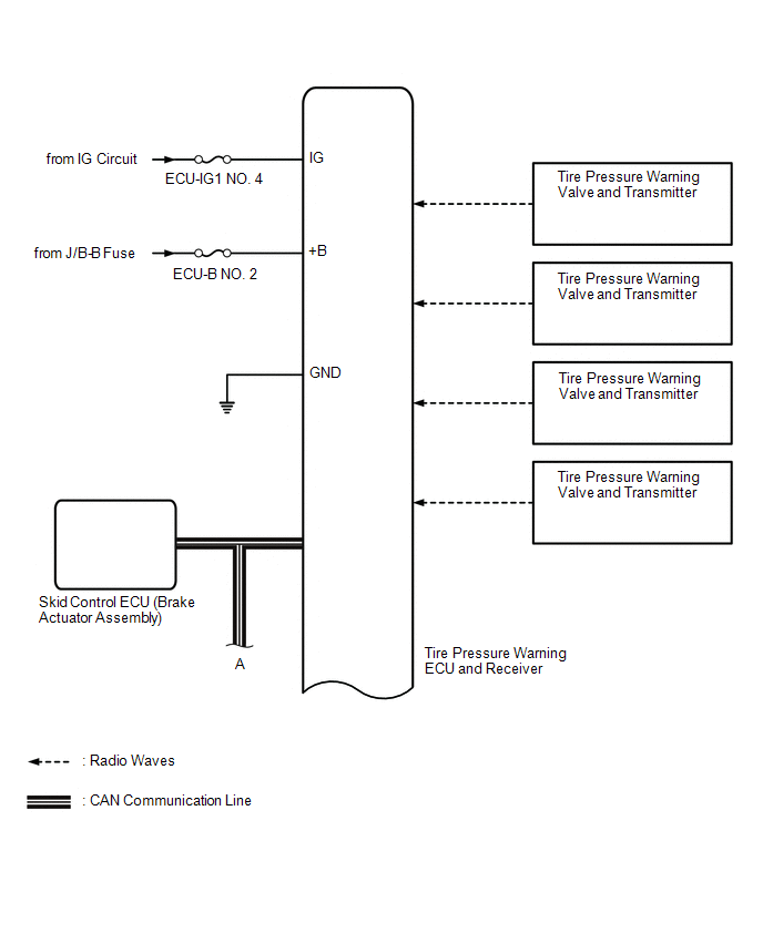
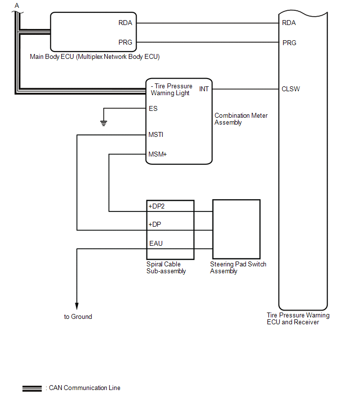
HINT:
Each tire pressure warning valve and transmitter sends its transmitter ID, temperature and tire pressure information to the tire pressure warning ECU and receiver.
|
Transmitting ECU (Transmitter) |
Receiving ECU | Signal |
Communication Method |
|---|---|---|---|
|
Combination Meter Assembly |
Main Body ECU (Multiplex Network Body ECU) |
Vehicle speed signal |
CAN communication line |
|
Main Body ECU (Multiplex Network Body ECU) |
Combination Meter Assembly |
Tire pressure warning light signal |
CAN communication line |
|
Skid Control ECU (Brake Actuator Assembly) |
Tire Pressure Warning ECU and Receiver |
Speed sensor signal | CAN communication line |
TERMINALS OF ECU
CHECK TIRE PRESSURE WARNING ECU AND RECEIVER
(a) Disconnect the K11 tire pressure warning ECU and receiver connector and measure the voltage or resistance on the wire harness side.
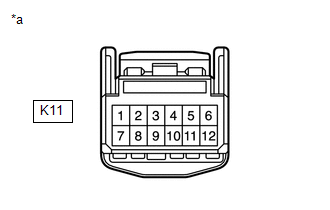
|
*a | Front view of wire harness connector (to Tire Pressure Warning ECU and Receiver) |
|
Terminal No. (Symbol) | Wiring Color |
Terminal Description | Condition |
Specified Condition |
|---|---|---|---|---|
|
K11-1 (IG) - K11-12 (GND) |
B - BR | IG power source |
Engine switch on (IG) |
10 to 16 V |
|
K11-7 (+B) - K11-12 (GND) |
LA-R - BR | Power supply (from battery) |
Always | 10 to 16 V |
|
K11-9 (CANH) - K11-10 (CANL) |
L - W | CAN communication line |
Engine switch off | 54 to 69 Ω |
|
K11-12 (GND) - Body ground |
BR - Body ground | Ground |
Always | Below 1 Ω |
(b) Connect the K11 tire pressure warning ECU and receiver connector.
(c) Measure the voltage according to the value(s) in the table below. If the result is not as specified, the ECU may be malfunctioning.
HINT:
Measure the values on the wire harness side while the connector is connected.

|
*a | Component with harness connected (Tire Pressure Warning ECU and Receiver) |
- | - |
|
Terminal No. (Symbol) | Wiring Color |
Terminal Description | Condition |
Specified Condition |
|---|---|---|---|---|
|
K11-3 (CLSW) - K11-12 (GND) |
SB - BR | Tire pressure warning reset switch |
| Below 1.5 V |
| 8 to 15 V | |||
|
K11-4 (RDA) - K11-12 (GND) |
GR - BR | Output signals |
Engine switch on (IG) |
Pulse generation (see waveform 1) |
|
K11-5 (PRG) - K11-12 (GND) |
R - BR | Input signals |
Engine switch on (IG) |
Pulse generation (see waveform 1) |
(d) Using an oscilloscope, check waveform 1.
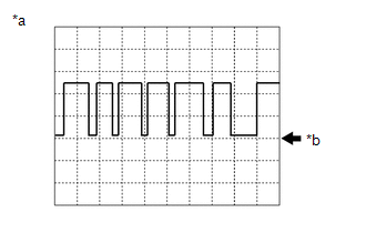
|
*a | Example |
|
*b | GND |
|
Item | Contents |
|---|---|
|
Terminal | K11-4 (RDA) - K11-12 (GND) K11-5 (PRG) - K11-12 (GND) |
|
Tool setting | 5 V/DIV, 5 ms./DIV. |
|
Vehicle condition | Engine switch on (IG) |
HINT:
The waveform shown in the illustration is an example. If the tester displays a waveform that alternates between high and low, where high is a voltage that is between the IG power source voltage and a voltage 2.2 V lower than the IG power source voltage, and where low is a voltage of between 0 and 1.2 V, the ECU can be judged normal.
TEST MODE PROCEDURE
TEST MODE (SIGNAL CHECK MODE) PROCEDURE
HINT:
After the tire pressure warning ECU and receiver completes the signal check for each inspection item, the DTCs for systems that are determined to be normal will be cleared.
The DTCs for other inspection items may not be cleared when only a certain signal is inspected.
(a) Turn the engine switch off.
(b) Connect the Techstream to the DLC3.
(c) Turn the engine switch on (IG).
(d) Turn the Techstream on.
(e) Enter the following menus: Chassis / Tire Pressure Monitor / Utility / Signal Check.
Chassis > Tire Pressure Monitor > Utility|
Tester Display |
|---|
| Signal Check |
HINT:
Every time the test mode (signal check mode) DTC clear conditions are satisfied, the tire pressure warning light illuminates for 1 second. Following this, the tire pressure warning light blinks at 0.125 second intervals.
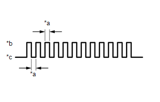
|
*a | 0.125 sec. |
|
*b | ON |
|
*c | OFF |
(f) Tire pressure warning reset switch check (DTC C2198).
(1) Select "Set Pressure" on the multi-information display and press the "OK" switch (steering pad switch assembly).
(g) Transmitter data reception check (DTCs C2181 to C2184).
(1) Wait for 1.5 minutes with the vehicle stopped, or drive the vehicle at a speed of 50 km/h (31 mph) or more for 1 minute.
HINT:
The tire pressure warning valve and transmitters send signals to the tire pressure warning ECU and receiver once every 1.5 minutes while the vehicle is stopped and once every minute while driving.
(h) Check that the tire pressure warning system test mode (signal check mode) DTCs are cleared.
|
Test Mode (Signal Check Mode) DTC |
Test Signal | Test Mode (Signal Check Mode) DTC Clear Condition |
|---|---|---|
|
C2181 to C2184 | Transmitter Data |
Data is received from the relevant transmitter which has a registered ID in the tire pressure warning ECU and receiver. |
|
C2198 | Tire Pressure Warning Reset Switch Signal |
A signal is received indicating that the steering pad switch assembly is operated, "Set Pressure" on the multi-information display is selected and the "OK" switch (steering pad switch assembly) is pressed. |
(i) Result
HINT:
After the signal check is completed, check for test mode (signal check mode) DTCs to confirm the system status.
|
Condition | Procedure |
|---|---|
|
Test mode (signal check mode) DTCs are output |
Repair the faulty part and enter Signal Check again |
|
Test mode (signal check mode) DTCs are cleared |
No problem |
(j) End of test mode (signal check mode)
(1) After completing test mode (signal check mode), turn the engine switch off and disconnect the Techstream.
(k) Test mode (signal check mode) DTCs
(1) If a trouble code is displayed during the test mode (signal check mode) DTC check, check the diagnosis procedure listed for that code. For details of each code, refer to Link below.
|
DTC No. | Detection Item |
Trouble Area | Link |
|---|---|---|---|
|
C2181 | Transmitter ID1 not received |
|
|
|
C2182 | Transmitter ID2 not received |
|
|
|
C2183 | Transmitter ID3 not received |
|
|
|
C2184 | Transmitter ID4 not received |
|
|
|
C2198 | Initialization switch error |
|
|
DESCRIPTION
The tire pressure warning ECU and receiver identifies the tire position for each tire pressure warning valve and transmitter according to the wheel speed signals from the skid control ECU and acceleration rate signal from each acceleration sensor built into each tire pressure warning valve and transmitter.
CAUTION / NOTICE / HINT
NOTICE:
for Registration:
Click here 
for Initialization
Click here
PROCEDURE
|
1. | TIRE PRESSURE WARNING VALVE AND TRANSMITTER |
(a) Set the tire pressure to the specified value.
Click here
(b) Turn the engine switch off.
(c) Connect the Techstream to the DLC3.
(d) Turn the engine switch on (IG).
(e) Turn the Techstream on.
(f) Enter the following menus: Chassis / Tire Pressure Monitor / Data List.
(g) Display the "ID Tire Inflation Pressure" value for each wheel using the Techstream.
Chassis > Tire Pressure Monitor > Data List|
Tester Display | Measurement Item |
Range | Normal Condition |
Diagnostic Note |
|---|---|---|---|---|
|
ID 1 Tire Inflation Pressure |
ID1 tire inflation pressure |
min.: Absolute pressure (abs) / 0 kPa (0 kgf/cm2, 0 psi), Relative pressure (Gauge) / 0 kPa (0 kgf/cm2, 0 psi) max.: Absolute pressure (abs) / 480 kPa (4.9 kgf/cm2, 70 psi), Relative pressure (Gauge) / 380 kPa (3.9 kgf/cm2, 55 psi) |
Actual tire inflation pressure |
If N/A is displayed, data has not been received.*1 |
|
ID 2 Tire Inflation Pressure |
ID2 tire inflation pressure |
min.: Absolute pressure (abs) / 0 kPa (0 kgf/cm2, 0 psi), Relative pressure (Gauge) / 0 kPa (0 kgf/cm2, 0 psi) max.: Absolute pressure (abs) / 480 kPa (4.9 kgf/cm2, 70 psi), Relative pressure (Gauge) / 380 kPa (3.9 kgf/cm2, 55 psi) |
Actual tire inflation pressure |
If N/A is displayed, data has not been received.*1 |
|
ID 3 Tire Inflation Pressure |
ID3 tire inflation pressure |
min.: Absolute pressure (abs) / 0 kPa (0 kgf/cm2, 0 psi), Relative pressure (Gauge) / 0 kPa (0 kgf/cm2, 0 psi) max.: Absolute pressure (abs) / 480 kPa (4.9 kgf/cm2, 70 psi), Relative pressure (Gauge) / 380 kPa (3.9 kgf/cm2, 55 psi) |
Actual tire inflation pressure |
If N/A is displayed, data has not been received.*1 |
|
ID 4 Tire Inflation Pressure |
ID4 tire inflation pressure |
min.: Absolute pressure (abs) / 0 kPa (0 kgf/cm2, 0 psi), Relative pressure (Gauge) / 0 kPa (0 kgf/cm2, 0 psi) max.: Absolute pressure (abs) / 480 kPa (4.9 kgf/cm2, 70 psi), Relative pressure (Gauge) / 380 kPa (3.9 kgf/cm2, 55 psi) |
Actual tire inflation pressure |
If N/A is displayed, data has not been received.*1 |
HINT:
*1: It may take a few minutes until the values are displayed.
Chassis > Tire Pressure Monitor > Data List|
Tester Display |
|---|
| ID 1 Tire Inflation Pressure |
|
ID 2 Tire Inflation Pressure |
|
ID 3 Tire Inflation Pressure |
|
ID 4 Tire Inflation Pressure |
(h) Rapidly reduce the tire pressure for each wheel at least 40 kPa (0.4 kgf/cm2, 5.8 psi) within 30 seconds.
NOTICE:
(i) Read the "ID Tire Inflation Pressure" value and identify the tire with reduced pressure, and record the corresponding tire pressure warning valve and transmitter (ID1 to ID4).
(j) Repeat for each tire.
(k) Set the tire pressure to the specified value.
Click here
|
| 2. |
PERFORM INITIALIZATION |
(a) Leave the vehicle with the engine switch turned off for 15 minutes or more.
HINT:
After the vehicle has been stopped for 15 minutes or more, the tire pressure warning valve and transmitter will transmit radio wave signals more frequently for the first several minutes of driving.
(b) Perform initialization to clear the existing tire position information.
Click here
|
| 3. |
IDENTIFY TIRE POSITION DURING DRIVING |
(a) Turn the engine switch off.
(b) Connect the Techstream to the DLC3.
(c) Drive the vehicle at 40 km/h (25 mph) or more for 10 to 30 minutes in 1 trip.
HINT:
Do not drive the vehicle in reverse gear while performing Tire Position Identification. If the vehicle is driven in reverse gear while performing Tire Position Identification, identification information will be discarded and Tire Position Identification may take longer than usual.
(d) Turn the Techstream on.
(e) Enter the following menus: Chassis / Tire Pressure Monitor / Data List.
(f) Without turning off the engine switch, check the tire position for each transmitter.
Chassis > Tire Pressure Monitor > Data List|
Tester Display | Measurement Item |
Range | Normal Condition |
Diagnostic Note |
|---|---|---|---|---|
|
ID 1 Tire Position | ID1 Tire Position |
No Information or FL or FR or RL or RR or Spare or Judging |
ID1 tire position is displayed |
If no tire position information is stored, "No Information" will be displayed. |
|
ID 2 Tire Position | ID2 Tire Position |
No Information or FL or FR or RL or RR or Spare or Judging |
ID2 tire position is displayed |
If no tire position information is stored, "No Information" will be displayed. |
|
ID 3 Tire Position | ID3 Tire Position |
No Information or FL or FR or RL or RR or Spare or Judging |
ID3 tire position is displayed |
If no tire position information is stored, "No Information" will be displayed. |
|
ID 4 Tire Position | ID4 Tire Position |
No Information or FL or FR or RL or RR or Spare or Judging |
ID4 tire position is displayed |
If no tire position information is stored, "No Information" will be displayed. |
|
Tester Display |
|---|
| ID 1 Tire Position |
|
ID 2 Tire Position |
|
ID 3 Tire Position |
|
ID 4 Tire Position |
|
Result | Proceed to |
|---|---|
|
A transmitter with its tire position as "Judging" exists. |
A |
| No transmitter with its tire position as "Judging" exists, and no tire pressures are displayed on the multi-information display. |
B |
| No transmitter with its tire position as "Judging" exists, and tire pressures are displayed on the multi-information display. |
C |
| B |
 | GO TO TIRE PRESSURE WARNING LIGHT CIRCUIT INSPECTION PROCEDURE |
| C |
| END |
|
| 4. |
CHECK TIRE PRESSURE WARNING VALVE AND TRANSMITTER |
(a) Without turning off the engine switch, check each transmitter with its tire position displayed as "Judging".
(b) Enter the following menus: Chassis / Tire Pressure Monitor / Data List.
(c) Without turning off the engine switch, check the number of times the transmitter signal and speed sensor signal have synchronized.
Example: Transmitter ID1 installed to front wheel LH
Chassis > Tire Pressure Monitor > Data List|
Tester Display | Measurement Item |
Range | Normal Condition |
Diagnostic Note |
|---|---|---|---|---|
|
ID 1 - FL Wheel Speed Synchronization Count |
ID1 - FL Wheel Speed Synchronization Count |
min.: 0, max.: 255 | Actual Synchronization Count |
- |
|
Tester Display |
|---|
| ID 1 - FL Wheel Speed Synchronization Count |
|
ID 1 - FR Wheel Speed Synchronization Count |
|
ID 1 - RL Wheel Speed Synchronization Count |
|
ID 1 - RR Wheel Speed Synchronization Count |
|
ID 2 - FL Wheel Speed Synchronization Count |
|
ID 2 - FR Wheel Speed Synchronization Count |
|
ID 2 - RL Wheel Speed Synchronization Count |
|
ID 2 - RR Wheel Speed Synchronization Count |
|
ID 3 - FL Wheel Speed Synchronization Count |
|
ID 3 - FR Wheel Speed Synchronization Count |
|
ID 3 - RL Wheel Speed Synchronization Count |
|
ID 3 - RR Wheel Speed Synchronization Count |
|
ID 4 - FL Wheel Speed Synchronization Count |
|
ID 4 - FR Wheel Speed Synchronization Count |
|
ID 4 - RL Wheel Speed Synchronization Count |
|
ID 4 - RR Wheel Speed Synchronization Count |
OK:
The transmitter signal and speed sensor signal have synchronized one or more times.
| NG | | REPLACE TIRE PRESSURE WARNING VALVE AND TRANSMITTER |
|
| 5. |
CHECK FREQUENCY RECEIVING CONDITION |
(a) Check that the following conditions are not met:
(1) Facilities or devices that use similar radio frequencies are located in the vicinity of the vehicle.
(2) Devices using similar radio frequencies are used in the vehicle.
OK:
Facilities or devices that use similar radio frequencies are not located in the vicinity of the vehicle.
HINT:
Radio wave transmissions may be interrupted due to the surroundings or devices installed by the user.
| OK | | IDENTIFY TIRE POSITION DURING DRIVING AGAIN |
| NG | | CHECK IF ANY DEVICE IS INSTALLED BY USER |
DESCRIPTION
If the tire pressure warning ECU and receiver detects any problems, the tire pressure warning light blinks for 1 minute then illuminates, and tire pressure monitoring is disabled at the same time. At this time, the ECU stores a DTC in memory.
The tire pressure warning ECU and receiver sends the tire pressure warning light illumination request signal to the main body ECU (multiplex network body ECU) via a direct line. The main body ECU (multiplex network body ECU) then sends the signal to the combination meter assembly via CAN communication.
WIRING DIAGRAM
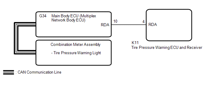
CAUTION / NOTICE / HINT
NOTICE:
 after registration
of the transmitter IDs into the tire pressure warning ECU and receiver if the ECU has been replaced.
after registration
of the transmitter IDs into the tire pressure warning ECU and receiver if the ECU has been replaced.
PROCEDURE
|
1. | CHECK FOR DTC (CAN COMMUNICATION SYSTEM) |
(a) Check if CAN communication system DTCs are output.
Click here
|
Result | Proceed to |
|---|---|
|
DTCs are not output | A |
|
DTCs are output | B |
| B |
 | GO TO CAN COMMUNICATION SYSTEM |
|
| 2. |
CHECK DTC OUTPUT (B1247) |
(a) Clear the DTCs.
Chassis > Tire Pressure Monitor > Clear DTCs(b) Turn the engine switch off.
(c) Turn the engine switch on (IG).
(d) Check for DTCs.
Chassis > Tire Pressure Monitor > Trouble Codes|
Result | Proceed to |
|---|---|
|
B1247 is not output | A |
|
B1247 is output | B |
| B |
| GO TO DTC (B1247) |
|
| 3. |
CHECK OPERATION OF TIRE PRESSURE WARNING LIGHT (ACTIVE TEST) |
(a) Turn the engine switch off.
(b) Connect the Techstream to the DLC3.
(c) Turn the engine switch on (IG).
(d) Turn the Techstream on.
(e) Enter the following menus: Body Electrical / Combination Meter / Active Test.
(f) Check the condition of the tire pressure warning light using the Techstream.
Body Electrical > Combination Meter > Active Test|
Tester Display | Measurement Item |
Control Range | Diagnostic Note |
|---|---|---|---|
|
Tire Pressure Warning System Indicator |
Tire pressure warning light |
OFF or ON | - |
|
Tester Display |
|---|
| Tire Pressure Warning System Indicator |
OK:
The tire pressure warning light turns on or off in accordance with the Techstream operation.
| OK | | REPLACE TIRE PRESSURE WARNING ECU AND RECEIVER |
| NG | | GO TO METER / GAUGE SYSTEM |
DESCRIPTION
The tire pressure warning ECU and receiver receives signals from the skid control ECU (brake actuator assembly) via CAN communication system.
|
DTC No. | Detection Item |
DTC Detection Condition | Trouble Area |
Note |
|---|---|---|---|---|
| U0129 |
Lost Communication with Brake System Control Module |
Lost communication with skid control ECU (brake actuator assembly) |
| - |
PROCEDURE
| 1. |
GO TO CAN COMMUNICATION SYSTEM |
(a) Go to CAN communication system.
Click here 
| NEXT |  | END |
Toyota Avalon (XX50) 2019-2022 Service & Repair Manual > 2gr-fks Engine Mechanical: Engine Assembly
Components COMPONENTS ILLUSTRATION *A Type A *B Type B *1 FRONT FENDER APRON SEAL LH *2 FRONT FENDER APRON SEAL RH *3 FRONT LOWER BUMPER ABSORBER *4 FRONT WHEEL OPENING EXTENSION PAD LH *5 FRONT WHEEL OPENING EXTENSION PAD RH *6 NO. 1 ENGINE UNDER COVER *7 REAR ENGINE UNDER COVER LH *8 REAR ENGINE U ...