Toyota Avalon (XX50) 2019-2022 Service & Repair Manual: Terminals Of Ecu

TERMINALS OF ECU

CHECK TIRE PRESSURE WARNING ECU AND RECEIVER

(a) Disconnect the K11 tire pressure warning ECU and receiver connector and measure the voltage or resistance on the wire harness side.

*a

Front view of wire harness connector

(to Tire Pressure Warning ECU and Receiver)

Terminal No. (Symbol)

Wiring Color

Terminal Description

Condition

Specified Condition

K11-1 (IG) - K11-12 (GND)

B - BR

IG power source

Engine switch on (IG)

10 to 16 V

K11-7 (+B) - K11-12 (GND)

LA-R - BR

Power supply (from battery)

Always

10 to 16 V

K11-9 (CANH) - K11-10 (CANL)

L - W

CAN communication line

Engine switch off

54 to 69 Ω

K11-12 (GND) - Body ground

BR - Body ground

Ground

Always

Below 1 Ω

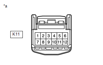
(b) Connect the K11 tire pressure warning ECU and receiver connector.

(c) Measure the voltage according to the value(s) in the table below. If the result is not as specified, the ECU may be malfunctioning.

HINT:

Measure the values on the wire harness side while the connector is connected.

*a

Component with harness connected

(Tire Pressure Warning ECU and Receiver)

-

-

Terminal No. (Symbol)

Wiring Color

Terminal Description

Condition

Specified Condition

K11-3 (CLSW) - K11-12 (GND)

SB - BR

Tire pressure warning reset switch

  • Engine switch on (IG)
  • Steering pad switch assembly operated, "Set Pressure" selected on the multi-information display and "OK" switch (steering pad switch assembly) pressed and held

Below 1.5 V

  • Engine switch on (IG)
  • "OK" switch (steering pad switch assembly) off

8 to 15 V

K11-4 (RDA) - K11-12 (GND)

GR - BR

Output signals

Engine switch on (IG)

Pulse generation (see waveform 1)

K11-5 (PRG) - K11-12 (GND)

R - BR

Input signals

Engine switch on (IG)

Pulse generation (see waveform 1)

(d) Using an oscilloscope, check waveform 1.

*a

Example

*b

GND

Waveform 1:

Item

Contents

Terminal

K11-4 (RDA) - K11-12 (GND)

K11-5 (PRG) - K11-12 (GND)

Tool setting

5 V/DIV, 5 ms./DIV.

Vehicle condition

Engine switch on (IG)

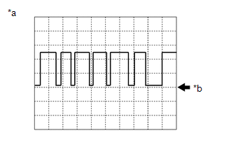
HINT:

The waveform shown in the illustration is an example. If the tester displays a waveform that alternates between high and low, where high is a voltage that is between the IG power source voltage and a voltage 2.2 V lower than the IG power source voltage, and where low is a voltage of between 0 and 1.2 V, the ECU can be judged normal.

    System Diagram

    Test Mode Procedure

    See More:

    Toyota Avalon (XX50) 2019-2022 Service & Repair Manual > Front Console Box: Disassembly
    DISASSEMBLY PROCEDURE 1. REMOVE CONSOLE REAR END PANEL SUB-ASSEMBLY (a) Disengage the 4 claws and 4 clips as shown in the illustration. Remove in this Direction (b) Disconnect each connector. *A w/ Seat Heater System (c) Disengage the clamp to remove the console rear end panel sub-assembly. 2. REMOV ...

    Toyota Avalon (XX50) 2019-2022 Owners Manual

    Toyota Avalon (XX50) 2019-2022 Service & Repair Manual

    © 2024 Copyright www.tavalon.net
    0.0172