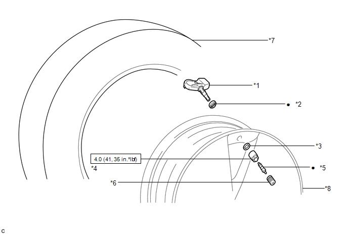
COMPONENTS
ILLUSTRATION
|
*1 | TIRE PRESSURE WARNING VALVE AND TRANSMITTER |
*2 | GROMMET |
|
*3 | WASHER |
*4 | NUT |
|
*5 | VALVE CORE |
*6 | TIRE VALVE CAP |
|
*7 | TIRE |
*8 | DISC WHEEL |
 |
N*m (kgf*cm, ft.*lbf): Specified torque |
● | Non-reusable part |
DISPOSAL
CAUTION / NOTICE / HINT
HINT:
The tire pressure warning valve and transmitter is powered by a lithium battery. When disposing of the tire pressure warning valve and transmitter, remove the battery and dispose of it properly.
PROCEDURE
1. DISPOSE OF TIRE PRESSURE WARNING VALVE AND TRANSMITTER
 |
Urethane |
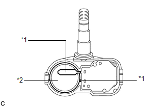
(a) Remove the urethane that protects the lithium battery and the circuit board.
| (b) Cut the 2 terminals to remove the lithium battery from the tire pressure warning valve and transmitter. |
|
INSTALLATION
CAUTION / NOTICE / HINT
NOTICE:
PROCEDURE
1. INSTALL TIRE PRESSURE WARNING VALVE AND TRANSMITTER
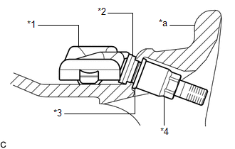
(a) Install a new grommet to the tire pressure warning valve and transmitter.
NOTICE:
A new tire pressure warning valve and transmitter comes with a grommet installed. Make sure not to install an extra grommet.
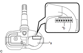
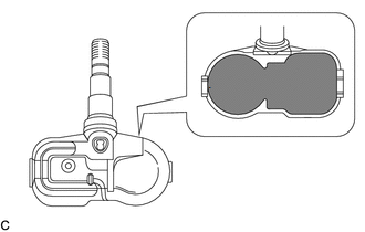
| (b) Write down the 7-digit transmitter ID number shown in the illustration. |
|
(c) Insert the tire pressure warning valve and transmitter with grommet from the inside of the rim.
NOTICE:
| (d) Install the washer to the tire pressure warning valve and transmitter from the outside of the rim, and using an 11 mm deep socket wrench, tighten the nut. Torque: 4.0 N·m {41 kgf·cm, 35 in·lbf} NOTICE:
|
|
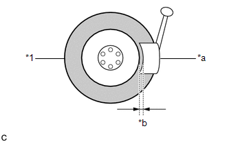
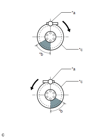
(e) Set the tire and disc wheel onto the mounting machine as shown in the illustration.
|
*a | Mount Tool of the Mounting Machine |
|
*b | 60° |
|
*c | Rim |
 |
Rim Rotating Direction |
 |
Area for Tire Pressure Warning Valve and Transmitter |
NOTICE:
(f) Apply a sufficient coat of soapy water or equivalent to the tire bead and rim.
NOTICE:
Do not apply soapy water or equivalent directly to the tire pressure warning valve and transmitter.
(g) Using a mounting machine, install the tire to the disc wheel.
NOTICE:
(h) Install a new valve core.
(i) Inflate the tire to the specified tire inflation pressure.
Click here 
(j) After the tire is inflated, the nut may be loose. Using an 11 mm deep socket wrench, retighten the nut to the specified torque.
Torque:
4.0 N·m {41 kgf·cm, 35 in·lbf}
NOTICE:
No further tightening is required once the nut is tightened to the specified torque.
(k) Check the surroundings of the tire pressure warning valve and transmitter for air leaks with soapy water or equivalent.
(1) If air is leaking from the valve core, press the valve core several times to remove foreign matter. Replace the valve core as necessary.
(2) If air is leaking from around the tire pressure warning valve and transmitter, check if the grommet, washer and nut are not deformed, damaged or contaminated with foreign matter. Replace the grommet, washer or nut as necessary.
(l) Install the tire valve cap.
2. INSTALL WHEEL ASSEMBLY
Click here
3. INSPECT TIRES
Click here
4. REGISTER TRANSMITTER ID
for HV Model: Click here
for Gasoline Model: Click here
5. INSPECT TIRE PRESSURE WARNING SYSTEM
for HV Model: Click here
for Gasoline Model: Click here
6. PERFORM INITIALIZATION
for HV Model: Click here
for Gasoline Model: Click here
REMOVAL
CAUTION / NOTICE / HINT
The necessary procedures (adjustment, calibration, initialization or registration) that must be performed after parts are removed and installed, or replaced during tire pressure warning valve and transmitter removal/installation are shown below.
Necessary Procedures After Parts Removed/Installed/Replaced (for Gasoline Model)|
Replacement Part or Procedure |
Necessary Procedures | Effects/Inoperative when not Performed |
Link |
|---|---|---|---|
| Tire pressure warning valve and transmitter |
|
|
for Registration
for Initialization |
|
Replacement Part or Procedure |
Necessary Procedures | Effects/Inoperative when not Performed |
Link |
|---|---|---|---|
| Tire pressure warning valve and transmitter |
|
| for Registration for Initialization
|
PROCEDURE
1. REMOVE WHEEL ASSEMBLY
Click here 
2. REMOVE TIRE PRESSURE WARNING VALVE AND TRANSMITTER
(a) Remove the tire valve cap.
NOTICE:
Keep the removed tire valve cap.
(b) Remove the valve core to release the air from the tire.
NOTICE:
Make sure that a sufficient amount of air has been released.
(c) Using an 11 mm deep socket wrench, remove the nut and washer.
(d) Drop the tire pressure warning valve and transmitter with grommet into the tire.
HINT:
The grommet may remain attached to the rim.
| (e) Using a tire remover, remove the tire from the disc wheel. NOTICE:
|
|
(f) Take out the tire pressure warning valve and transmitter with grommet from the tire.
(g) Remove the grommet from the tire pressure warning valve and transmitter.
Toyota Avalon (XX50) 2019-2022 Service & Repair Manual > Can Communication System(for Gasoline Model): Open in One Side of Bus 3 Branch Line. Open in One Side of Bus 4 Branch Line. Open in One Side of Bus 5 Branch Line
Open in One Side of Bus 3 Branch Line DESCRIPTION When the CAN bus main lines are normal (no open, short to ground, short to +B or short between lines) and there is an ECU or sensor on the "Communication Bus Check" screen that is indicated as not communicating or whose connection status on the "Comm ...