CUSTOMIZE PARAMETERS
CUSTOMIZE LUGGAGE COMPARTMENT DOOR OPENER SYSTEM
HINT:
The following items can be customized.
NOTICE:
(a) Customizing with the Techstream
(1) Connect the Techstream to the DLC3.
(2) Turn the power switch on (IG).
(3) Turn the Techstream on.
(4) Enter the following menus: Customize Setting / Door Lock.
(5) Select the setting by referring to the table below.
Door Lock|
Tester Display | Description |
Default | Setting |
ECU |
|---|---|---|---|---|
| Trunk Link with Door Lock |
Function that opens the luggage compartment door when the luggage electrical key switch is pressed and all doors are unlocked using the entry door lock function, wireless door lock function, mechanical key or door control switch. | ON |
0:OFF,1:ON | Main body ECU (Multiplex network body ECU) |
DATA LIST / ACTIVE TEST
DATA LIST
NOTICE:
In the table below, the values listed under "Normal Condition" are reference values. Do not depend solely on these reference values when deciding whether a part is faulty or not.
HINT:
Using the Techstream to read the Data List allows the values or states of switches, sensors, actuators and other items to be read without removing any parts. This non-intrusive inspection can be very useful because intermittent conditions or signals may be discovered before parts or wiring is disturbed. Reading the Data List information early in troubleshooting is one way to save diagnostic time.
(a) Connect the Techstream to the DLC3.
(b) Turn the power switch on (IG).
(c) Turn the Techstream on.
(d) Enter the following menus: Body Electrical / (desired system) / Data List.
(e) Read the Data List according to the display on the Techstream.
Body Electrical > Main Body > Data List|
Tester Display | Measurement Item |
Range | Normal Condition |
Diagnostic Note |
|---|---|---|---|---|
|
Trunk Lock Position | Luggage compartment door lock signal |
Lock or Unlock | Lock: Luggage compartment door lock assembly locked Unlock: Luggage compartment door lock assembly unlocked |
- |
| Trunk/BDoor Open SW |
Luggage compartment door opening switch signal |
OFF or ON | OFF: Luggage compartment door opening switch off ON: Luggage compartment door opening switch on |
- |
| Luggage Courtesy SW |
Luggage compartment door courtesy light switch signal |
OFF or ON | OFF: Luggage compartment door courtesy light switch off ON: Luggage compartment door courtesy light switch on |
- |
|
Tester Display | Measurement Item |
Range | Normal Condition |
Diagnostic Note |
|---|---|---|---|---|
|
Tr/B-Door Unlock SW | Luggage electrical key switch |
OFF or ON | OFF: Luggage electrical key switch not pressed ON: Luggage electrical key switch pressed |
When this item is abnormal, there is a malfunction in the luggage electrical key switch or related parts. |
ACTIVE TEST
HINT:
Using the Techstream to perform the Active Tests allows relays, VSVs and actuators and other items to be operated without removing any parts. This non-intrusive functional inspection can be very useful because intermittent operation may be discovered before parts or wiring is disturbed. Performing Active Tests early in troubleshooting is one way to save diagnostic time. Data List information can be displayed while performing Active Tests.
(a) Connect the Techstream to the DLC3.
(b) Turn the power switch on (IG).
(c) Turn the Techstream on.
(d) Enter the following menus: Body Electrical / Main Body / Active Test.
(e) Perform the Active Test according to the display on the Techstream.
Body Electrical > Main Body > Active Test|
Tester Display | Measurement Item |
Control Range | Diagnostic Note |
|---|---|---|---|
|
Trunk and Back-Door Open |
Operate luggage compartment door lock assembly latch release |
OFF or ON | - |
CAUTION / NOTICE / HINT
HINT:
PROCEDURE
|
1. | VEHICLE BROUGHT TO WORKSHOP |
|
| 2. |
CUSTOMER PROBLEM ANALYSIS |
HINT:
|
What |
Vehicle model, system name |
|
When |
Date, time, occurrence frequency |
|
Where |
Road conditions |
|
Under what conditions? |
Driving conditions, weather conditions |
|
How did it happen? |
Problem symptoms |
|
| 3. |
PRE-CHECK |
(a) Measure the auxiliary battery voltage with the power switch off.
Standard Voltage:
11 to 14 V
If the voltage is below 11 V, recharge or replace the auxiliary battery before proceeding to the next step.
(b) Check the fuses and relays.
(c) Check the connector connections and terminals to make sure that there are no abnormalities such as loose connections, deformation, etc.
|
| 4. |
CHECK COMMUNICATION FUNCTION OF CAN COMMUNICATION SYSTEM* |
(a) Using the Techstream, check for CAN communication system DTCs.
Click here

|
Result | Proceed to |
|---|---|
|
CAN DTCs are not output |
A |
| CAN DTCs are output |
B |
| B |
 | GO TO CAN COMMUNICATION SYSTEM |
|
| 5. |
PROBLEM SYMPTOMS TABLE |
(a) Refer to Problem Symptoms Table.
Click here
|
Result | Proceed to |
|---|---|
|
Fault is not listed in Problem Symptoms Table |
A |
| Fault is listed in Problem Symptoms Table |
B |
| B |
| GO TO STEP 7 |
|
| 6. |
OVERALL ANALYSIS AND TROUBLESHOOTING* |
(a) Operation Check
Click here
(b) Terminals of ECU
Click here
(c) Data List / Active Test
Click here
(d) Inspection
|
| 7. |
REPAIR OR REPLACE |
|
| 8. |
CONFIRMATION TEST |
| NEXT | | END |
DESCRIPTION
The main body ECU (multiplex network body ECU) receives switch signals from the luggage compartment door opening switch assembly and operates the luggage compartment door lock assembly to open the luggage compartment door.
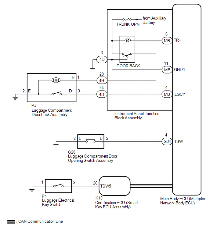
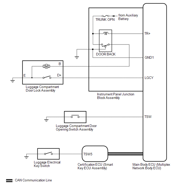
WIRING DIAGRAM
CAUTION / NOTICE / HINT
NOTICE:
Click here 
Click here
PROCEDURE
|
1. | CHECK POWER DOOR LOCK CONTROL SYSTEM |
(a) Check power door lock control system operation.
Click here
OK:
Power door lock control system is normal.
| NG |  | GO TO POWER DOOR LOCK CONTROL SYSTEM |
|
| 2. |
CHECK WIRELESS DOOR LOCK CONTROL SYSTEM |
(a) Check wireless door lock control system operation.
Click here
OK:
Wireless door lock control system is normal.
| NG | | GO TO WIRELESS DOOR LOCK CONTROL SYSTEM |
|
| 3. |
PERFORM ACTIVE TEST USING TECHSTREAM (Trunk and Back-Door Open) |
(a) Connect the Techstream to the DLC3.
(b) Turn the power switch on (IG).
(c) Turn the Techstream on.
(d) Enter the following menus: Body Electrical / Main Body / Active Test.
(e) Perform the Active Test according to the display on the Techstream.
Body Electrical > Main Body > Active Test|
Tester Display | Measurement Item |
Control Range | Diagnostic Note |
|---|---|---|---|
|
Trunk and Back-Door Open |
Operate luggage compartment door lock assembly latch release |
OFF or ON | - |
|
Tester Display |
|---|
| Trunk and Back-Door Open |
OK:
Luggage compartment door lock assembly latch release motor operates normally.
| NG | | GO TO STEP 9 |
|
| 4. |
READ VALUE USING TECHSTREAM (Trunk/BDoor Open SW, Luggage Courtesy SW) |
(a) Enter the following menus: Body Electrical / Main Body / Data List.
(b) Read the Data List according to the display on the Techstream.
Body Electrical > Main Body > Data List|
Tester Display | Measurement Item |
Range | Normal Condition |
Diagnostic Note |
|---|---|---|---|---|
|
Trunk/BDoor Open SW | Luggage compartment door opening switch signal |
OFF or ON | OFF: Luggage compartment door opening switch off ON: Luggage compartment door opening switch on |
- |
| Luggage Courtesy SW |
Luggage compartment door courtesy light switch signal |
OFF or ON | OFF: Luggage compartment door courtesy light switch off ON: Luggage compartment door courtesy light switch on |
- |
|
Tester Display |
|---|
| Trunk/BDoor Open SW |
|
Luggage Courtesy SW |
OK:
The Techstream display changes correctly in response to the ON/OFF operation of the luggage compartment door opening switch or luggage compartment door courtesy light switch.
|
Result | Proceed to |
|---|---|
|
OK | A |
|
NG (Trunk/BDoor Open SW) |
B |
| NG (Luggage Courtesy SW) |
C |
| B |
| GO TO STEP 7 |
| C |
| GO TO LIGHTING SYSTEM |
|
| 5. |
READ VALUE USING TECHSTREAM (Tr/B-Door Unlock SW) |
(a) Enter the following menus: Body Electrical / Smart Key / Data List.
(b) Read the Data List according to the display on the Techstream.
Body Electrical > Smart Key > Data List|
Tester Display | Measurement Item |
Range | Normal Condition |
Diagnostic Note |
|---|---|---|---|---|
|
Tr/B-Door Unlock SW | Luggage electrical key switch |
OFF or ON | OFF: Luggage electrical key switch not pressed ON: Luggage electrical key switch pressed |
When this item is abnormal, there is a malfunction in the luggage electrical key switch or related parts. |
OK:
The Techstream display changes correctly in response to the operation of the luggage electrical key switch.
| NG | | GO TO SMART KEY SYSTEM (for Entry Function) |
|
| 6. |
CHECK MAIN BODY ECU (MULTIPLEX NETWORK BODY ECU) |
(a) Temporarily replace the main body ECU (multiplex network body ECU) with a new or known good one.
Click here
(b) Check that the luggage door opener system is normal.
| OK | | END (MAIN BODY ECU (MULTIPLEX NETWORK BODY ECU) WAS DEFECTIVE) |
| NG | | REPLACE CERTIFICATION ECU (SMART KEY ECU ASSEMBLY) |
| 7. |
INSPECT LUGGAGE COMPARTMENT DOOR OPENING SWITCH ASSEMBLY |
(a) Remove the luggage compartment door opening switch assembly.
Click here
(b) Inspect the luggage compartment door opening switch assembly.
Click here
| NG | | REPLACE LUGGAGE COMPARTMENT DOOR OPENING SWITCH ASSEMBLY |
|
| 8. |
CHECK HARNESS AND CONNECTOR (MAIN BODY ECU (MULTIPLEX NETWORK BODY ECU) - LUGGAGE COMPARTMENT DOOR OPENING SWITCH ASSEMBLY AND BODY GROUND) |
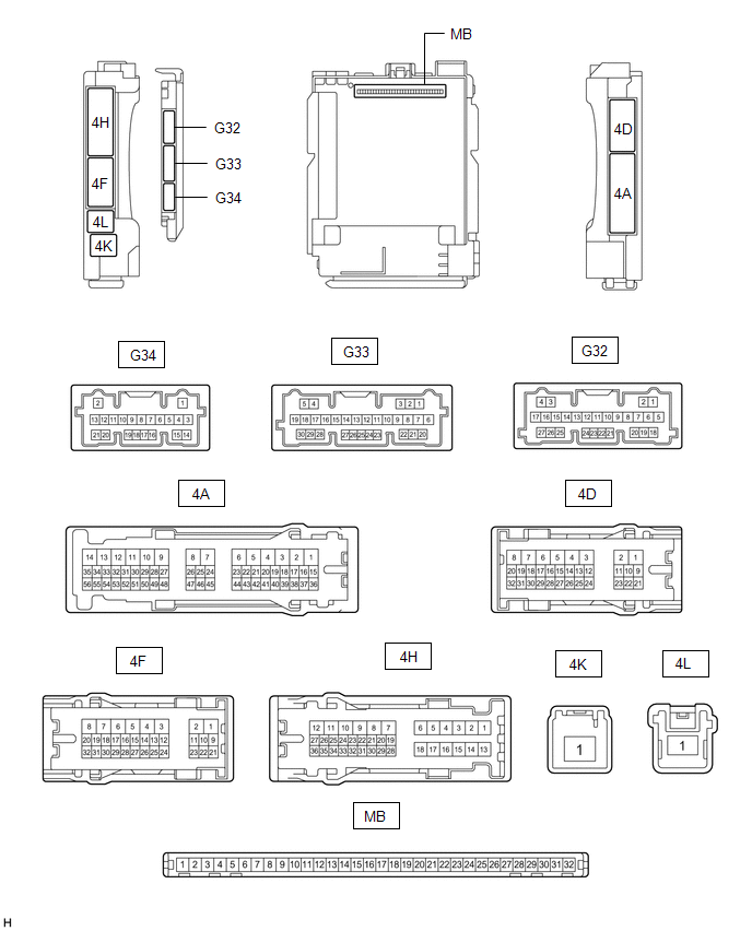
(a) Disconnect the G34 main body ECU (multiplex network body ECU) connector.
(b) Measure the resistance according to the value(s) in the table below.
Standard Resistance:
|
Tester Connection | Condition |
Specified Condition |
|---|---|---|
|
G34-4 (TSW) - G28-5 (B) |
Always | Below 1 Ω |
|
G28-2 (L) - Body ground |
Always | Below 1 Ω |
|
G34-4 (TSW) or G28-5 (B) - Body ground |
Always | 10 kΩ or higher |
| OK | | REPLACE MAIN BODY ECU (MULTIPLEX NETWORK BODY ECU) |
| NG | | REPAIR OR REPLACE HARNESS OR CONNECTOR |
| 9. |
INSPECT LUGGAGE COMPARTMENT DOOR LOCK ASSEMBLY |
(a) Remove the luggage compartment door lock assembly.
Click here
(b) Inspect the luggage compartment door lock assembly.
Click here
| NG | | REPLACE LUGGAGE COMPARTMENT DOOR LOCK ASSEMBLY |
|
| 10. |
CHECK HARNESS AND CONNECTOR (LUGGAGE COMPARTMENT DOOR LOCK ASSEMBLY - INSTRUMENT PANEL JUNCTION BLOCK ASSEMBLY AND BODY GROUND) |
(a) Disconnect the 4H instrument panel junction block assembly connector.
(b) Measure the resistance according to the value(s) in the table below.
Standard Resistance:
|
Tester Connection | Condition |
Specified Condition |
|---|---|---|
|
P3-3 (D+) - 4H-34 | Always |
Below 1 Ω |
|
P3-1 (B) - 4H-20 | Always |
Below 1 Ω |
|
P3-2 (E) - Body ground |
Always | Below 1 Ω |
|
P3-3 (D+) or 4H-34 - Body ground |
Always | 10 kΩ or higher |
|
P3-1 (B) or 4H-20 - Body ground |
Always | 10 kΩ or higher |
| NG | | REPAIR OR REPLACE HARNESS OR CONNECTOR |
|
| 11. |
CHECK INSTRUMENT PANEL JUNCTION BLOCK ASSEMBLY |
(a) Temporarily replace the instrument panel junction block assembly with a new or known good one.
Click here
(b) Check that the luggage door opener system is normal.
| OK | | END (INSTRUMENT PANEL JUNCTION BLOCK ASSEMBLY WAS DEFECTIVE) |
| NG | | REPLACE MAIN BODY ECU (MULTIPLEX NETWORK BODY ECU) |
OPERATION CHECK
BASIC FUNCTION INSPECTION
(a) When the luggage compartment door opening switch assembly is pressed, check that the luggage compartment door unlatches.
PARTS LOCATION
ILLUSTRATION
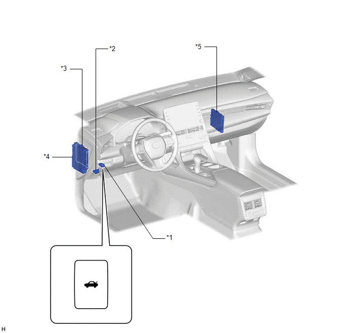
|
*1 | LUGGAGE COMPARTMENT DOOR OPENING SWITCH ASSEMBLY |
*2 | DLC3 |
|
*3 | MAIN BODY ECU (MULTIPLEX NETWORK BODY ECU) |
*4 | INSTRUMENT PANEL JUNCTION BLOCK ASSEMBLY - DOOR BACK RELAY - TRUNK OPN FUSE |
|
*5 | CERTIFICATION ECU (SMART KEY ECU ASSEMBLY) |
- | - |
ILLUSTRATION
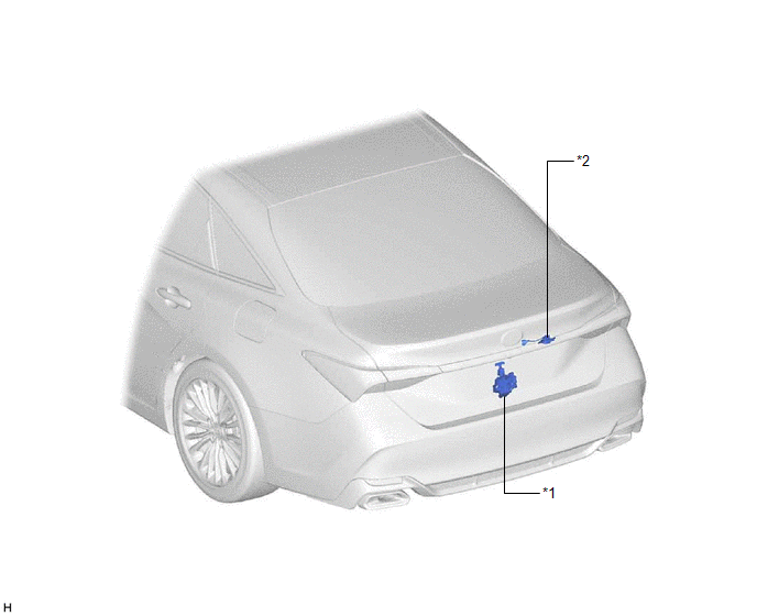
|
*1 | LUGGAGE COMPARTMENT DOOR LOCK ASSEMBLY |
*2 | LUGGAGE ELECTRICAL KEY SWITCH |
PRECAUTION
PRECAUTION FOR DISCONNECTING CABLE FROM NEGATIVE AUXILIARY BATTERY TERMINAL
NOTICE:
When disconnecting the cable from the negative (-) auxiliary battery terminal, initialize the following systems after the cable is reconnected.
|
System Name | See Procedure |
|---|---|
|
Lane Departure Alert System (w/ Steering Control) |
|
|
Intelligent Clearance Sonar System | |
|
Parking Assist Monitor System | |
|
Panoramic View Monitor System | |
|
Pre-collision System | |
|
Lighting System (for HV Model with Cornering Light) |
PROBLEM SYMPTOMS TABLE
HINT:
|
Symptom | Suspected Area |
Link |
|---|---|---|
| Luggage door opener does not operate |
Proceed to "Luggage Compartment Door Opener does not Operate" |
|
SYSTEM DESCRIPTION
LUGGAGE COMPARTMENT DOOR OPENER SYSTEM DESCRIPTION
(a) If the luggage compartment door opening switch assembly is pressed and the luggage compartment door is closed, a luggage compartment door lock assembly open operation signal is sent to the main body ECU (multiplex network body ECU). Then the main body ECU (multiplex network body ECU) unlatches the luggage compartment door.
FUNCTION OF MAIN COMPONENTS
|
Item | Outline |
|---|---|
|
Luggage compartment door opening switch assembly |
Turns the luggage compartment door opener system ON/OFF |
|
Luggage compartment door lock assembly |
Opens the luggage compartment door via a signal from the main body ECU (multiplex network body ECU) |
|
Main body ECU (Multiplex network body ECU) |
Receives a luggage compartment door lock assembly open operation signal, and controls the luggage compartment door opener system |
SYSTEM DIAGRAM
Luggage Compartment Door Opener System
 Communication Table
 |
Sender | Receiver |
Signal | Line |
|---|---|---|---|
|
Certification ECU (Smart Key ECU Assembly) |
Main Body ECU (Multiplex Network Body ECU) |
Luggage compartment door lock assembly open operation signal |
CAN |
TERMINALS OF ECU
CHECK INSTRUMENT PANEL JUNCTION BLOCK ASSEMBLY AND MAIN BODY ECU (MULTIPLEX NETWORK BODY ECU)
(a) Remove the main body ECU (multiplex network body ECU) from the instrument panel junction block assembly.
Click here 
(b) Measure the resistance according to the value(s) in the table below.
HINT:
Measure the values on the wire harness side with the connectors disconnected.
|
Terminal No. (Symbol) | Wiring Color |
Terminal Description | Condition |
Specified Condition |
|---|---|---|---|---|
|
G32-19 (GND2) - Body ground |
W-B - Body ground | Ground |
Always | Below 1 Ω |
(c) Reconnect the instrument panel junction block assembly connectors.
(d) Measure the resistance and voltage according to the value(s) in the table below.
HINT:
Measure the values on the wire harness side with the connectors disconnected.
|
Terminal No. (Symbol) | Wiring Color |
Terminal Description | Condition |
Specified Condition |
|---|---|---|---|---|
|
MB-11 (GND1) - Body ground |
- | Ground |
Always | Below 1 Ω |
|
MB-31 (BECU) - Body ground |
- | Auxiliary battery power supply |
Power switch off | 11 to 14 V |
|
MB-30 (ACC) - Body ground |
- | ACC power supply |
Power switch on (ACC) |
11 to 14 V |
|
MB-30 (ACC) - Body ground |
- | ACC power supply |
Power switch off | Below 1 V |
|
MB-32 (IG) - Body ground |
- | IG power supply |
Power switch on (IG) |
11 to 14 V |
|
MB-32 (IG) - Body ground |
- | IG power supply |
Power switch off | Below 1 V |
(e) Install the main body ECU (multiplex network body ECU) to the instrument panel junction block assembly.
Click here
(f) Measure the voltage and check for pulses according to the value(s) in the table below.
|
Terminal No. (Symbol) | Wiring Color |
Terminal Description | Condition |
Specified Condition |
|---|---|---|---|---|
|
G34-4 (TSW) - Body ground |
LG - Body ground |
Luggage compartment door opening switch signal |
Luggage compartment door opening switch on |
Below 1 V |
|
Power switch off, all doors closed and luggage compartment door opening switch off |
Pulse generation | |||
|
4H-34 (LGCY) - Body ground |
LA-GR - Body ground |
Luggage compartment door courtesy light switch assembly input signal |
Luggage compartment door open |
Below 1 V |
|
Luggage compartment door closed |
11 to 14 V | |||
|
4H-20 (TR+) - Body ground |
LA-G - Body ground |
Luggage compartment door open relay output signal |
Luggage compartment door opening switch on |
11 to 14 V |
|
Luggage compartment door opening switch off |
Below 1 V |
CHECK CERTIFICATION ECU (SMART KEY ECU ASSEMBLY)
Click here
Toyota Avalon (XX50) 2019-2022 Service & Repair Manual > Door Lock: Door Control Transmitter
ComponentsCOMPONENTS ILLUSTRATION *1 TRANSMITTER BATTERY *2 MECHANICAL KEY *3 TRANSMITTER HOUSING COVER *4 TRANSMITTER HOUSING CASE *5 SMART KEY DOOR CONTROL TRANSMITTER HOUSING SET - - InspectionINSPECTION PROCEDURE 1. INSPECT ELECTRICAL KEY TRANSMITTER SUB-ASSEMBLY (a) Inspect the operation of th ...


