DISASSEMBLY CAUTION / NOTICE / HINT The necessary procedures (adjustment, calibration, initialization, or registration) that must be performed after parts are removed and installed, or replaced during rear door removal/installation are shown below. Necessary Procedure After Parts Removed/Installed/Replaced (for Gasoline Model)
HINT:
PROCEDURE 1. PRECAUTION NOTICE: After turning the engine switch (for Gasoline Model) or power switch (for HV Model) off, waiting time may be required before disconnecting the cable from the negative (-) auxiliary battery terminal. Therefore, make sure to read the disconnecting the cable from the negative (-) auxiliary battery terminal notices before proceeding with work. Click here
2. REMOVE LUGGAGE TRIM SERVICE HOLE COVER (for HV Model) Click here 3. DISCONNECT CABLE FROM NEGATIVE AUXILIARY BATTERY TERMINAL for A25A-FXS: Click here for 2GR-FKS: Click here 4. REMOVE REAR DOOR ARMREST COVER SUB-ASSEMBLY
5. REMOVE REAR DOOR TRIM ASSEMBLY COVER
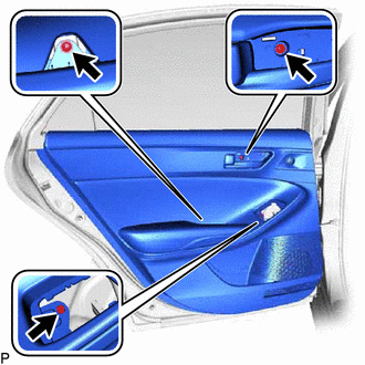
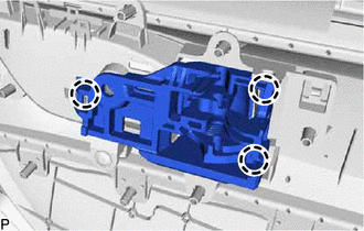
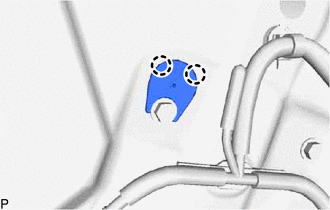
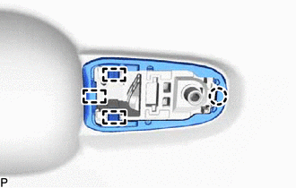
6. REMOVE REAR POWER WINDOW REGULATOR SWITCH ASSEMBLY WITH REAR DOOR UPPER ARMREST BASE PANEL (a) Apply protective tape to the rear door trim board sub-assembly as shown in the illustration. 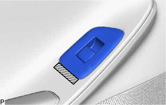
(b) Using a moulding remover, disengage the 3 claws as shown in the illustration. 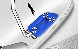
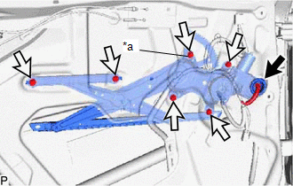
(c) Disconnect the connector to remove the rear power window regulator switch assembly with rear door upper armrest base panel. 7. REMOVE REAR DOOR TRIM BOARD SUB-ASSEMBLY
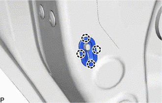
(b) Disengage the 8 clips as shown in the illustration. 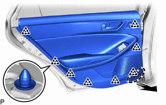
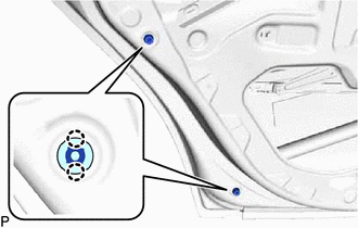
(c) Disengage the 6 claws and guide as shown in the illustration. 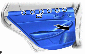
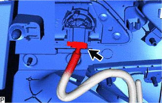
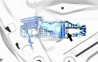
(d) Disconnect the rear door lock open lever remote control cable and rear door inside lock/unlock knob locking cable as shown in the illustration. 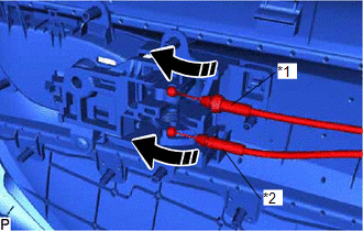
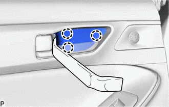
8. REMOVE REAR DOOR INSIDE HANDLE SUB-ASSEMBLY
9. REMOVE REAR NO. 2 SPEAKER ASSEMBLY Click here
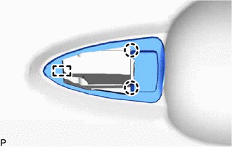
10. REMOVE REAR DOOR SPEAKER GRILLE SUB-ASSEMBLY (a) Remove the 2 screws. 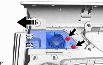
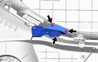
(b) Disengage the 2 guides to remove the rear door speaker grille sub-assembly as shown in the illustration. 11. REMOVE REAR DOOR TRIM BODY BRACKET
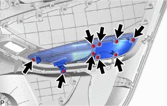
12. REMOVE REAR DOOR TRIM COVER
(b) Disengage the guide to remove the rear armrest assembly with rear door trim cover as shown in the illustration. 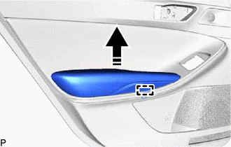
(c) Disengage the 2 guides to remove the rear door trim cover as shown in the illustration. 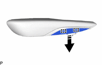
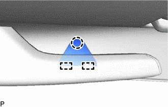
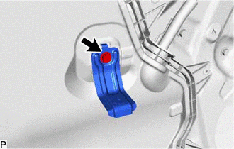
13. REMOVE REAR DOOR PULL HANDLE (a) Remove the 2 screws. 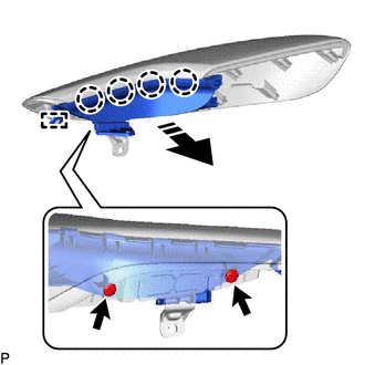
(b) Disengage the 4 claws and guide to remove the rear door pull handle as shown in the illustration. 14. REMOVE REAR DOOR ORNAMENT (a) Disengage the 2 guides to remove the rear door ornament as shown in the illustration. 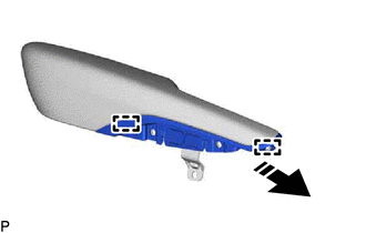
15. REMOVE REAR SPEAKER ASSEMBLY Click here 16. REMOVE REAR DOOR NO. 1 TRIM BRACKET
17. REMOVE REAR DOOR SERVICE HOLE COVER
(b) Disengage the 3 clamps.
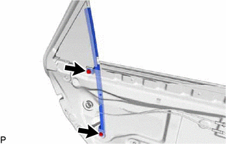
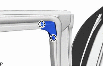
18. REMOVE REAR DOOR INNER GLASS WEATHERSTRIP (a) Disengage the 2 guides and remove the rear door inner glass weatherstrip as shown in the illustration. 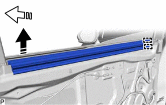
19. REMOVE REAR DOOR NO. 2 SERVICE HOLE COVER
(b) Remove the rear door No. 2 service hole cover as shown in the illustration. 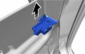
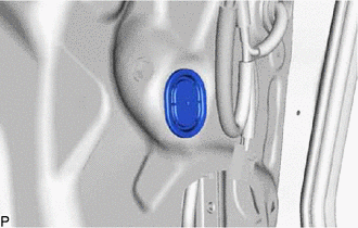
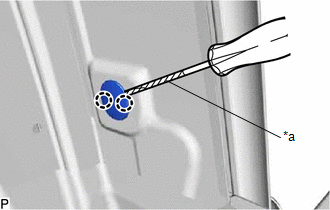
20. REMOVE HOLE PLUG
21. REMOVE REAR DOOR GLASS RUN
22. REMOVE REAR DOOR REAR LOWER WINDOW FRAME SUB-ASSEMBLY
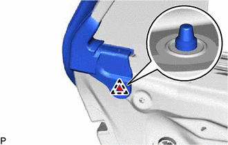
23. REMOVE REAR DOOR FRAME GARNISH
24. REMOVE REAR DOOR CHECK ASSEMBLY (a) Remove the 2 nuts, bolt and rear door check assembly. 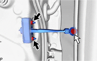
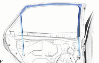
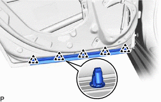
25. REMOVE REAR DOOR WEATHERSTRIP
(b) Using a clip remover, disengage the 21 clips and remove the rear door weatherstrip. 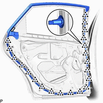
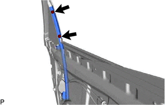
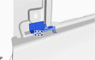
26. REMOVE REAR DOOR REAR GUIDE SEAL
(b) Remove the rear door rear guide seal as shown in the illustration. 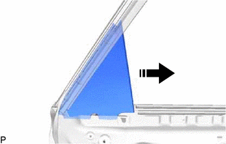
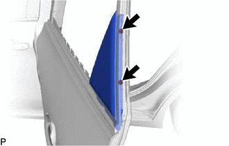
27. REMOVE REAR DOOR GLASS SUB-ASSEMBLY
(b) Connect the rear power window regulator switch assembly. (c) for Gasoline Model: (1) Connect the cable to the negative (-) battery terminal. (d) for HV Model: (1) Connect the cable to the negative (-) auxiliary battery terminal. (e) for Gasoline Model: (1) Turn the engine switch on (IG). (f) for HV Model: (1) Turn the power switch on (IG). (g) Move the rear door glass sub-assembly so that the door glass bolts can be seen. (h) for Gasoline Model: (1) Turn the engine switch off. (i) for HV Model: (1) Turn the power switch off. (j) for Gasoline Model: (1) Disconnect the cable from the negative (-) battery terminal. (k) for HV Model: (1) Disconnect the cable from the negative (-) auxiliary battery terminal. (l) Disconnect the rear power window regulator switch assembly.
(n) Remove the rear door glass sub-assembly as shown in the illustration. NOTICE: Do not damage the rear door glass sub-assembly. 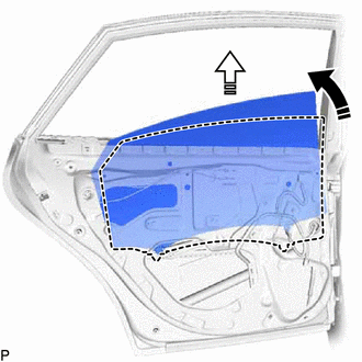
28. REMOVE REAR DOOR WINDOW REGULATOR ASSEMBLY
(c) Loosen the temporary bolt. NOTICE: Do not remove the temporary bolt. If the temporary bolt is removed, the rear door window regulator assembly may fall and cause damage. (d) Remove the 5 bolts and rear door window regulator assembly. (e) Remove the temporary bolt from the rear door window regulator assembly. 29. REMOVE REAR DOOR LOCK WITH MOTOR ASSEMBLY Click here
30. REMOVE REAR DOOR OUTSIDE HANDLE ASSEMBLY (a) Disengage the 2 claws and move the lever as shown in the illustration. 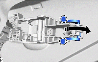
(b) Remove the rear door outside handle assembly as shown in the illustration. 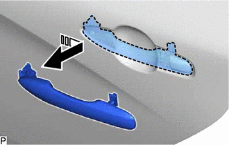
31. REMOVE REAR DOOR OUTSIDE HANDLE COVER
(b) Disengage the claw to remove the rear door outside handle cover. 32. REMOVE REAR DOOR FRONT OUTSIDE HANDLE PAD
33. REMOVE REAR DOOR REAR OUTSIDE HANDLE PAD
34. REMOVE REAR DOOR OUTSIDE HANDLE FRAME SUB-ASSEMBLY
(b) Disengage the claw and guide to remove rear door outside handle frame sub-assembly as shown in the illustration. 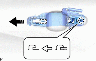
35. REMOVE REAR DOOR LOCK CHILD PROTECTION COVER
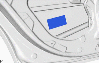
36. REMOVE REAR DOOR PANEL CUSHION
37. REMOVE REAR DOOR NO. 2 WEATHERSTRIP
38. REMOVE REAR DOOR BELT MOULDING ASSEMBLY Click here
39. REMOVE DOOR WINDOW FRAME MOULDING CLIP
40. REMOVE REAR DOOR WINDOW FRAME MOULDING (CENTER PILLAR SIDE) Click here
41. REMOVE REAR DOOR FRONT OUTSIDE SEAL
42. REMOVE REAR DOOR UPPER WINDOW FRAME MOULDING Click here
43. REMOVE REAR DOOR REAR WINDOW FRAME MOULDING Click here 44. REMOVE NO. 1 BLACK OUT TAPE Click here 45. REMOVE NO. 3 BLACK OUT TAPE Click here 46. REMOVE NO. 2 BLACK OUT TAPE Click here 47. REMOVE REAR DOOR NO. 3 WEATHERSTRIP (a) Remove the rear door No. 3 weatherstrip. 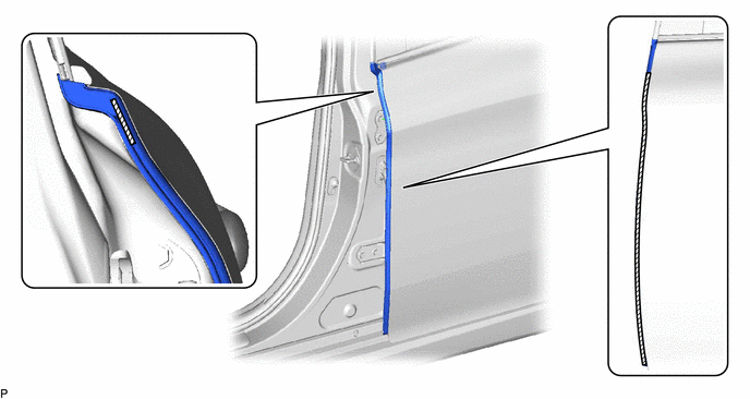
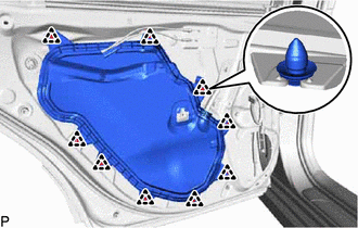
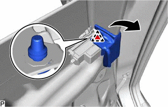
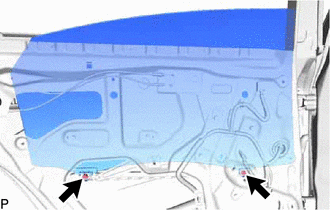
48. REMOVE REAR DOOR SILENCER PAD
| ||||||||||||||||||||||||||||||||||||||||||||||||||||||||||||||||||||||||||||||||||||||||||||||||||||||||||||||||||||||||||||||||||||||||||||||||||||||||||||||||||||||||||||||||||||||||||||||||||||||||||||
Toyota Avalon (XX50) 2019-2022 Service & Repair Manual > Brake System(for Gasoline Model): Problem Symptoms Table
PROBLEM SYMPTOMS TABLE HINT: Use the table below to help determine the cause of problem symptoms. If multiple suspected areas are listed, the potential causes of the symptoms are listed in order of probability in the "Suspected Area" column of the table. Check each symptom by checking the suspected ...