Toyota Avalon (XX50) 2019-2022 Service & Repair Manual: Removal

REMOVAL

CAUTION / NOTICE / HINT

The necessary procedures (adjustment, calibration, initialization, or registration) that must be performed after parts are removed and installed, or replaced during black out tape removal/installation are shown below.

Necessary Procedure After Parts Removed/Installed/Replaced (for Gasoline Model)

Replaced Part or Performed Procedure

Necessary Procedure

Effect/Inoperative Function When Necessary Procedures are not Performed

Link

*: When performing learning using the Techstream.

Click here

Disconnect cable from negative battery terminal

Perform steering sensor zero point calibration

Lane Departure Alert System (w/ Steering Control)

Pre-collision System

Intelligent Clearance Sonar System*

Lighting System (for Gasoline Model with Cornering Light)

Memorize steering angle neutral point

Parking Assist Monitor System

Panoramic View Monitor System

  • Rear door glass sub-assembly
  • Rear door glass run

Initialize power window control system

  • Auto up and down function
  • Jam protection function
  • Remote control function
  • Key-linked function
  • Wireless transmitter-linked function
  • Key-off operation function
  • Catch protection function
  • Window open warning function

Necessary Procedure After Parts Removed/Installed/Replaced (for HV Model)

Replaced Part or Performed Procedure

Necessary Procedure

Effect/Inoperative Function When Necessary Procedures are not Performed

Link

*: When performing learning using the Techstream.

Click here

Disconnect cable from negative auxiliary battery terminal

Perform steering sensor zero point calibration

Lane Departure Alert System (w/ Steering Control)

Pre-collision System

Intelligent Clearance Sonar System*

Lighting System (for HV Model with Cornering Light)

Memorize steering angle neutral point

Parking Assist Monitor System

Panoramic View Monitor System

  • Rear door glass sub-assembly
  • Rear door glass run

Initialize power window control system

  • Auto up and down function
  • Jam protection function
  • Remote control function
  • Key-linked function
  • Wireless transmitter-linked function
  • Key-off operation function
  • Catch protection function
  • Window open warning function

HINT:

  • Use the same procedure for the RH side and LH side.
  • The following procedure is for the LH side.

PROCEDURE

1. PRECAUTION

NOTICE:

After turning the engine switch (for Gasoline Model) or power switch (for HV Model) off, waiting time may be required before disconnecting the cable from the negative (-) auxiliary battery terminal. Therefore, make sure to read the disconnecting the cable from the negative (-) auxiliary battery terminal notices before proceeding with work.

Click here

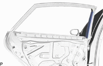
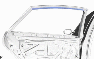
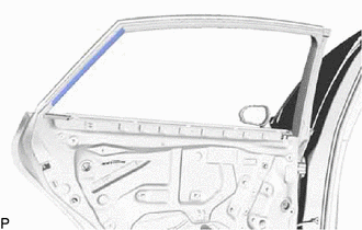
2. REMOVE LUGGAGE TRIM SERVICE HOLE COVER (for HV Model)

Click here

3. DISCONNECT CABLE FROM NEGATIVE AUXILIARY BATTERY TERMINAL

for A25A-FXS:

Click here

for 2GR-FKS:

Click here

4. REMOVE REAR DOOR ARMREST COVER SUB-ASSEMBLY

Click here

5. REMOVE REAR DOOR TRIM ASSEMBLY COVER

Click here

6. REMOVE REAR POWER WINDOW REGULATOR SWITCH ASSEMBLY WITH REAR DOOR UPPER ARMREST BASE PANEL

Click here

7. REMOVE REAR DOOR TRIM BOARD SUB-ASSEMBLY

Click here

8. REMOVE REAR DOOR NO. 1 TRIM BRACKET

Click here

9. REMOVE REAR DOOR SERVICE HOLE COVER

Click here

10. REMOVE REAR DOOR INNER GLASS WEATHERSTRIP

Click here

11. REMOVE REAR DOOR NO. 2 SERVICE HOLE COVER

Click here

12. REMOVE REAR DOOR GLASS RUN

Click here

13. REMOVE REAR DOOR REAR LOWER WINDOW FRAME SUB-ASSEMBLY

Click here

14. DISCONNECT REAR DOOR WEATHERSTRIP

Click here

15. REMOVE REAR DOOR REAR GUIDE SEAL

Click here

16. REMOVE REAR DOOR GLASS SUB-ASSEMBLY

Click here

17. REMOVE REAR DOOR CHECK ASSEMBLY

Click here

18. REMOVE REAR DOOR WEATHERSTRIP

Click here

19. REMOVE REAR DOOR FRAME GARNISH

Click here

20. REMOVE NO. 1 BLACK OUT TAPE

HINT:

When removing the No. 1 black out tape, heat the vehicle body and No. 1 black out tape using a heat light.

Heating Temperature

Item

Temperature

No. 1 Black Out Tape and Vehicle Body

40 to 60°C (104 to 140°F)

CAUTION:

  • Do not touch the heat light and heated parts, touching the heat light may result in burns.
  • Touching heated parts for a long time may result in burns.

*a

Heated Part

*b

Heat Light

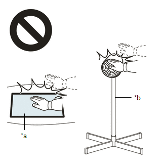
NOTICE:

Do not heat the vehicle body excessively.

(a) Using a heat light, heat the No. 1 black out tape and vehicle body.

(b) Pull back on one of the ends of the No. 1 black out tape to remove it.

HINT:

When pulling on the No. 1 black out tape, pull it parallel to the vehicle body.

21. REMOVE NO. 3 BLACK OUT TAPE

HINT:

When removing the No. 3 black out tape, heat the vehicle body and No. 3 black out tape using a heat light.

Heating Temperature

Item

Temperature

No. 3 Black Out Tape and Vehicle Body

40 to 60°C (104 to 140°F)

CAUTION:

  • Do not touch the heat light and heated parts, touching the heat light may result in burns.
  • Touching heated parts for a long time may result in burns.

*a

Heated Part

*b

Heat Light

NOTICE:

Do not heat the vehicle body excessively.

(a) Using a heat light, heat the No. 3 black out tape and vehicle body.

(b) Pull back on one of the ends of the No. 3 black out tape to remove it.

HINT:

When pulling on the No. 3 black out tape, pull it parallel to the vehicle body.

22. REMOVE NO. 2 BLACK OUT TAPE

HINT:

When removing the No. 2 black out tape, heat the vehicle body and No. 2 black out tape using a heat light.

Heating Temperature

Item

Temperature

No. 2 Black Out Tape and Vehicle Body

40 to 60°C (104 to 140°F)

CAUTION:

  • Do not touch the heat light and heated parts, touching the heat light may result in burns.
  • Touching heated parts for a long time may result in burns.

*a

Heated Part

*b

Heat Light

NOTICE:

Do not heat the vehicle body excessively.

(a) Using a heat light, heat the No. 2 black out tape and vehicle body.

(b) Pull back on one of the ends of the No. 2 black out tape to remove it.

HINT:

When pulling on the No. 2 black out tape, pull it parallel to the vehicle body.

    Installation

    Front Bumper

    See More:

    Toyota Avalon (XX50) 2019-2022 Service & Repair Manual > Can Communication System(for Gasoline Model): Open in Bus 1 Main Bus Line
    DESCRIPTION There may be an open circuit in one of the CAN main bus lines when the resistance between terminals 23 (CA1H) and 8 (CA1L) of the central gateway ECU (network gateway ECU) is 70 Ω or higher. Symptom Trouble Area Resistance between terminals 23 (CA1H) and 8 (CA1L) of the central gateway ...

    Toyota Avalon (XX50) 2019-2022 Owners Manual

    Toyota Avalon (XX50) 2019-2022 Service & Repair Manual

    © 2024 Copyright www.tavalon.net
    0.0201