COMPONENTS
ILLUSTRATION
|
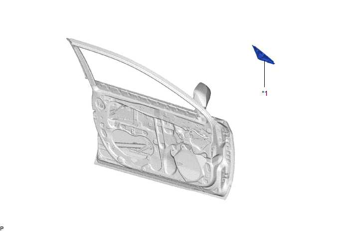
*1 | FRONT DOOR FRONT LOWER FRAME UPPER COVER |
- | - |
INSTALLATION
CAUTION / NOTICE / HINT
HINT:
PROCEDURE
1. INSTALL FRONT DOOR FRONT LOWER FRAME UPPER COVER
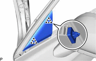
(a) Engage the 2 clips to install the front door front lower frame upper cover.
2. INSTALL FRONT DOOR BELT MOULDING ASSEMBLY
Click here

REMOVAL
CAUTION / NOTICE / HINT
The necessary procedures (adjustment, calibration, initialization, or registration) that must be performed after parts are removed and installed, or replaced during front door front lower frame upper cover removal/installation are shown below.
Necessary Procedure After Parts Removed/Installed/Replaced (for Gasoline Model)|
Replaced Part or Performed Procedure |
Necessary Procedure | Effect/Inoperative Function When Necessary Procedures are not Performed |
Link |
|---|---|---|---|
|
*: When performing learning using the Techstream.
Click here | |||
|
Disconnect cable from negative battery terminal |
Perform steering sensor zero point calibration |
Lane Departure Alert System (w/ Steering Control) |
|
|
Pre-collision System | |||
|
Intelligent Clearance Sonar System* | |||
|
Lighting System (for Gasoline Model with Cornering Light) | |||
|
Memorize steering angle neutral point |
Parking Assist Monitor System |
| |
|
Panoramic View Monitor System |
| ||
|
Front door glass sub-assembly | Initialize power window control system |
|
|
|
Replaced Part or Performed Procedure |
Necessary Procedure | Effect/Inoperative Function When Necessary Procedures are not Performed |
Link |
|---|---|---|---|
|
*: When performing learning using the Techstream.
Click here | |||
|
Disconnect cable from negative auxiliary battery terminal |
Perform steering sensor zero point calibration |
Lane Departure Alert System (w/ Steering Control) |
|
|
Pre-collision System | |||
|
Intelligent Clearance Sonar System* | |||
|
Lighting System (for HV Model with Cornering Light) | |||
|
Memorize steering angle neutral point |
Parking Assist Monitor System |
| |
|
Panoramic View Monitor System |
| ||
|
Front door glass sub-assembly | Initialize power window control system |
|
|
HINT:
PROCEDURE
1. REMOVE FRONT DOOR BELT MOULDING ASSEMBLY
Click here 
2. REMOVE FRONT DOOR FRONT LOWER FRAME UPPER COVER
| (a) Disengage the 2 clips to remove the front door front lower frame upper cover. |
|
Toyota Avalon (XX50) 2019-2022 Service & Repair Manual > 2gr-fks Intake / Exhaust: Vacuum Switching Valve(for Acis)
ComponentsCOMPONENTS ILLUSTRATION *1 NO. 1 VACUUM SWITCHING VALVE ASSEMBLY (for ACIS) *2 VACUUM HOSE SUB-ASSEMBLY *3 V-BANK COVER SUB-ASSEMBLY - - N*m (kgf*cm, ft.*lbf): Specified torque - - InspectionINSPECTION PROCEDURE 1. INSPECT NO. 1 VACUUM SWITCHING VALVE ASSEMBLY (for ACIS) (a) Measure the r ...