COMPONENTS
ILLUSTRATION
|
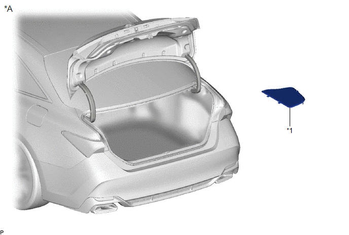
*A | for HV Model |
- | - |
|
*1 | LUGGAGE TRIM SERVICE HOLE COVER |
- | - |
ILLUSTRATION
|
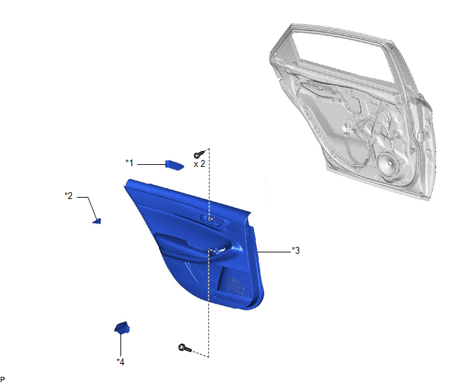
*1 | REAR DOOR ARMREST COVER SUB-ASSEMBLY |
*2 | REAR DOOR TRIM ASSEMBLY COVER |
|
*3 | REAR DOOR TRIM BOARD SUB-ASSEMBLY |
*4 | REAR POWER WINDOW REGULATOR SWITCH ASSEMBLY WITH REAR DOOR UPPER ARMREST BASE PANEL |
ILLUSTRATION
|
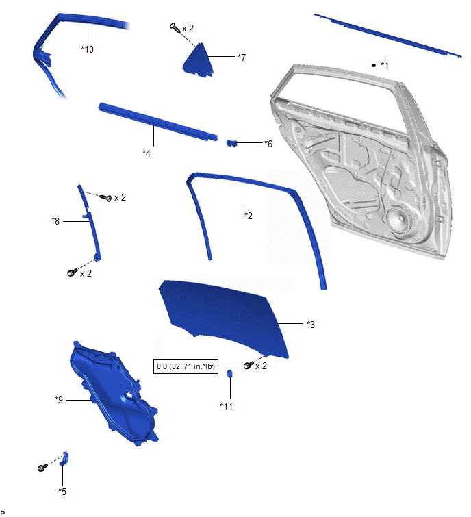
*1 | REAR DOOR BELT MOULDING ASSEMBLY |
*2 | REAR DOOR GLASS RUN |
|
*3 | REAR DOOR GLASS SUB-ASSEMBLY |
*4 | REAR DOOR INNER GLASS WEATHERSTRIP |
|
*5 | REAR DOOR NO. 1 TRIM BRACKET |
*6 | REAR DOOR NO. 2 SERVICE HOLE COVER |
|
*7 | REAR DOOR REAR GUIDE SEAL |
*8 | REAR DOOR REAR LOWER WINDOW FRAME SUB-ASSEMBLY |
|
*9 | REAR DOOR SERVICE HOLE COVER |
*10 | REAR DOOR WEATHERSTRIP |
|
*11 | HOLE PLUG |
- | - |
 |
N*m (kgf*cm, ft.*lbf): Specified torque |
● | Non-reusable part |
INSTALLATION
CAUTION / NOTICE / HINT
HINT:
PROCEDURE
1. PRECAUTION
NOTICE:
After turning the engine switch (for Gasoline Model) or power switch (for HV Model) off, waiting time may be required before disconnecting the cable from the negative (-) auxiliary battery terminal. Therefore, make sure to read the disconnecting the cable from the negative (-) auxiliary battery terminal notices before proceeding with work.
Click here

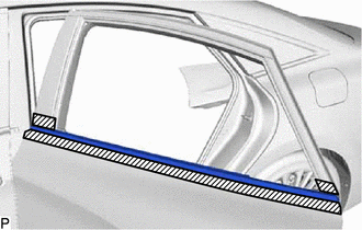
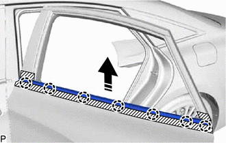
2. INSTALL REAR DOOR BELT MOULDING ASSEMBLY
(a) Engage the 7 claws to install a new rear door belt moulding assembly as shown in the illustration.

 |
Install in this Direction |
3. INSTALL REAR DOOR GLASS SUB-ASSEMBLY
Click here
4. INSTALL REAR DOOR REAR GUIDE SEAL
Click here
5. CONNECT REAR DOOR WEATHERSTRIP
Click here
6. INSTALL REAR DOOR REAR LOWER WINDOW FRAME SUB-ASSEMBLY
Click here
7. INSTALL REAR DOOR GLASS RUN
Click here
8. INSTALL REAR DOOR NO. 2 SERVICE HOLE COVER
Click here
9. INSTALL REAR DOOR INNER GLASS WEATHERSTRIP
Click here
10. INSTALL REAR DOOR SERVICE HOLE COVER
Click here
11. INSTALL REAR DOOR NO. 1 TRIM BRACKET
Click here
12. INSTALL REAR DOOR TRIM BOARD SUB-ASSEMBLY
Click here
13. INSTALL REAR POWER WINDOW REGULATOR SWITCH ASSEMBLY WITH REAR DOOR UPPER ARMREST BASE PANEL
Click here
14. INSTALL REAR DOOR TRIM ASSEMBLY COVER
Click here
15. INSTALL REAR DOOR ARMREST COVER SUB-ASSEMBLY
Click here
16. CONNECT CABLE TO NEGATIVE AUXILIARY BATTERY TERMINAL
for A25A-FXS:
Click here
for 2GR-FKS:
Click here
17. INSTALL LUGGAGE TRIM SERVICE HOLE COVER (for HV Model)
Click here
18. INITIALIZE POWER WINDOW CONTROL SYSTEM
for Gasoline Model:
Click here
for HV Model:
Click here
19. INSPECT POWER WINDOW OPERATION
for Gasoline Model:
Click here
for HV Model:
Click here
REMOVAL
CAUTION / NOTICE / HINT
The necessary procedures (adjustment, calibration, initialization, or registration) that must be performed after parts are removed and installed, or replaced during rear door belt moulding assembly removal/installation are shown below.
Necessary Procedure After Parts Removed/Installed/Replaced (for Gasoline Model)|
Replaced Part or Performed Procedure |
Necessary Procedure | Effect/Inoperative Function When Necessary Procedures are not Performed |
Link |
|---|---|---|---|
|
*: When performing learning using the Techstream.
Click here | |||
|
Disconnect cable from negative battery terminal |
Perform steering sensor zero point calibration |
Lane Departure Alert System (w/ Steering Control) |
|
|
Pre-collision System | |||
|
Intelligent Clearance Sonar System* | |||
|
Lighting System (for Gasoline Model with Cornering Light) | |||
|
Memorize steering angle neutral point |
Parking Assist Monitor System |
| |
|
Panoramic View Monitor System |
| ||
| Initialize power window control system |
|
|
|
Replaced Part or Performed Procedure |
Necessary Procedure | Effect/Inoperative Function When Necessary Procedures are not Performed |
Link |
|---|---|---|---|
|
*: When performing learning using the Techstream.
Click here | |||
|
Disconnect cable from negative auxiliary battery terminal |
Perform steering sensor zero point calibration |
Lane Departure Alert System (w/ Steering Control) |
|
|
Pre-collision System | |||
|
Intelligent Clearance Sonar System* | |||
|
Lighting System (for HV Model with Cornering Light) | |||
|
Memorize steering angle neutral point |
Parking Assist Monitor System |
| |
|
Panoramic View Monitor System |
| ||
| Initialize power window control system |
|
|
HINT:
PROCEDURE
1. PRECAUTION
NOTICE:
After turning the engine switch (for Gasoline Model) or power switch (for HV Model) off, waiting time may be required before disconnecting the cable from the negative (-) auxiliary battery terminal. Therefore, make sure to read the disconnecting the cable from the negative (-) auxiliary battery terminal notices before proceeding with work.
Click here

2. REMOVE LUGGAGE TRIM SERVICE HOLE COVER (for HV Model)
Click here
3. DISCONNECT CABLE FROM NEGATIVE AUXILIARY BATTERY TERMINAL
for A25A-FXS:
Click here
for 2GR-FKS:
Click here
4. REMOVE REAR DOOR ARMREST COVER SUB-ASSEMBLY
Click here
5. REMOVE REAR DOOR TRIM ASSEMBLY COVER
Click here
6. REMOVE REAR POWER WINDOW REGULATOR SWITCH ASSEMBLY WITH REAR DOOR UPPER ARMREST BASE PANEL
Click here
7. REMOVE REAR DOOR TRIM BOARD SUB-ASSEMBLY
Click here
8. REMOVE REAR DOOR NO. 1 TRIM BRACKET
Click here
9. REMOVE REAR DOOR SERVICE HOLE COVER
Click here
10. REMOVE REAR DOOR INNER GLASS WEATHERSTRIP
Click here
11. REMOVE REAR DOOR NO. 2 SERVICE HOLE COVER
Click here
12. REMOVE REAR DOOR GLASS RUN
Click here
13. REMOVE REAR DOOR REAR LOWER WINDOW FRAME SUB-ASSEMBLY
Click here
14. DISCONNECT REAR DOOR WEATHERSTRIP
Click here
15. REMOVE REAR DOOR REAR GUIDE SEAL
Click here
16. REMOVE REAR DOOR GLASS SUB-ASSEMBLY
Click here
17. REMOVE REAR DOOR BELT MOULDING ASSEMBLY
(a) Apply protective tape around the rear door belt moulding assembly as shown in the illustration.
 |
Protective Tape |
(b) Disengage the 7 claws to remove the rear door belt moulding assembly as shown in the illustration.
 |
Remove in this Direction |
Toyota Avalon (XX50) 2019-2022 Service & Repair Manual > Navigation System(for Gasoline Model): XM Tuner Antenna Disconnected (B15FE,B15FF). GVIF Disconnected (from Extension Module to H/U) (B153A). AV Signal Stoppage (Low Battery Voltage) (B158F)
XM Tuner Antenna Disconnected (B15FE,B15FF) DESCRIPTION These DTCs are stored when a malfunction occurs in the telephone antenna assembly which is connected to the radio and display receiver assembly. DTC No. Detection Item DTC Detection Condition Trouble Area B15FE XM Tuner Antenna Disconnected The ...

