COMPONENTS
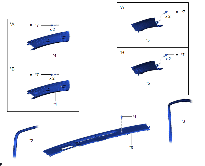
ILLUSTRATION
|
*A | w/o Front No. 3 Speaker |
*B | w/ Front No. 3 Speaker |
|
*1 | AUTOMATIC LIGHT CONTROL SENSOR |
*2 | FRONT DOOR OPENING TRIM WEATHERSTRIP LH |
|
*3 | FRONT DOOR OPENING TRIM WEATHERSTRIP RH |
*4 | FRONT PILLAR GARNISH LH |
|
*5 | FRONT PILLAR GARNISH RH |
*6 | NO. 1 DEFROSTER NOZZLE GARNISH |
|
*7 | CLIP |
- | - |
|
● | Non-reusable part |
- | - |
INSTALLATION
PROCEDURE
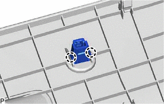
1. INSTALL AUTOMATIC LIGHT CONTROL SENSOR
(a) Engage the 2 claws to install the automatic light control sensor.
2. INSTALL NO. 1 DEFROSTER NOZZLE GARNISH
Click here 
3. INSTALL FRONT PILLAR GARNISH RH
HINT:
Use the same procedure as for the LH side.
Click here
4. INSTALL FRONT DOOR OPENING TRIM WEATHERSTRIP RH
Click here
5. INSTALL FRONT PILLAR GARNISH LH
Click here
6. INSTALL FRONT DOOR OPENING TRIM WEATHERSTRIP LH
Click here
ON-VEHICLE INSPECTION
PROCEDURE
1. INSPECT AUTOMATIC LIGHT CONTROL SENSOR
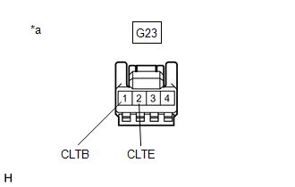
| (a) Disconnect the G23 automatic light control sensor connector. |
|
(b) Measure the voltage and resistance according to the value(s) in the table below.
Standard Voltage:
|
Tester Connection | Condition |
Specified Condition |
|---|---|---|
|
*1: for HV Model
*2: for Gasoline Model | ||
|
G23-1 (CLTB) - G23-2 (CLTE) |
Power switch off*1 |
Below 1 V |
|
Engine switch off*2 | ||
|
Power switch on (IG)*1 |
11 to 14 V | |
|
Engine switch on (IG)*2 | ||
Standard Resistance:
|
Tester Connection | Condition |
Specified Condition |
|---|---|---|
|
G23-2 (CLTE) - Body ground |
Always | Below 1 Ω |
If the result is not as specified, there may be a malfunction on the wire harness side.
(c) Connect the G23 automatic light control sensor connector.
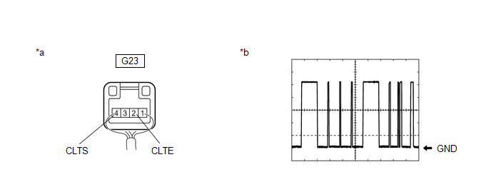
(d) Connect an oscilloscope to terminals G23-2 (CLTE) and G23-4 (CLTS) of the automatic light control sensor connector and check the waveform.
|
*a | Component with harness connected (Automatic Light Control Sensor) |
*b | Waveform |
OK:
|
Tester Connection | Condition |
Tool Setting | Specified Condition |
|---|---|---|---|
|
*1: for HV Model
*2: for Gasoline Model | |||
|
G23-2 (CLTE) - G23-4 (CLTS) |
Power switch on (IG)*1 |
2 V/DIV., 10 ms./DIV. |
Pulse generation (See waveform) |
|
Engine switch on (IG)*2 | |||
HINT:
The communication waveform changes according to the surrounding brightness.
If the result is not as specified, the automatic light control sensor may be malfunctioning.
REMOVAL
PROCEDURE
1. DISCONNECT FRONT DOOR OPENING TRIM WEATHERSTRIP LH
Click here 
2. REMOVE FRONT PILLAR GARNISH LH
Click here
3. DISCONNECT FRONT DOOR OPENING TRIM WEATHERSTRIP RH
HINT:
Use the same procedure as for the LH side.
4. REMOVE FRONT PILLAR GARNISH RH
HINT:
Use the same procedure as for the LH side.
5. REMOVE NO. 1 DEFROSTER NOZZLE GARNISH
Click here
6. REMOVE AUTOMATIC LIGHT CONTROL SENSOR
| (a) Disengage the 2 claws to remove the automatic light control sensor. |
|
Toyota Avalon (XX50) 2019-2022 Service & Repair Manual > Meter / Gauge System(for Hv Model): Customize Parameters. Data List / Active Test. Diagnostic Trouble Code Chart
Customize Parameters CUSTOMIZE PARAMETERS NOTICE: When the customer requests a change in a function, first make sure that the function can be customized. Be sure to make a note of the current settings before customizing. When troubleshooting a function, first make sure that the function is set to th ...