ADJUSTMENT CAUTION / NOTICE / HINT HINT:
PROCEDURE 1. PREPARE VEHICLE FOR HEADLIGHT AIM ADJUSTMENT (a) Prepare the vehicle:
2. PREPARE FOR HEADLIGHT AIMING (Using a headlight aim test machine) (a) Adjust the headlight aim in accordance with the headlight aim test machine instructions. 3. PREPARE FOR HEADLIGHT AIMING (Using a screen) (a) Prepare the vehicle: 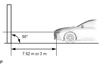
NOTICE: A distance of 7.62 m (25 ft.) between the vehicle center marks of the headlights and the wall is necessary for proper aim adjustment. If sufficient space is not available, secure a distance of exactly 3 m (9.84 ft.) to allow for checking and adjustment of headlight aim. (The size of the target zone will change with the distance, so follow the instructions in the illustration.) 
(b) Prepare a piece of thick white paper (approximately 2 m (6.56 ft.) (height) x 4 m (13.1 ft.) (width)) to use as a screen. (c) Draw a vertical line down the center of the screen (V line). (d) Set the screen as shown in the illustration. 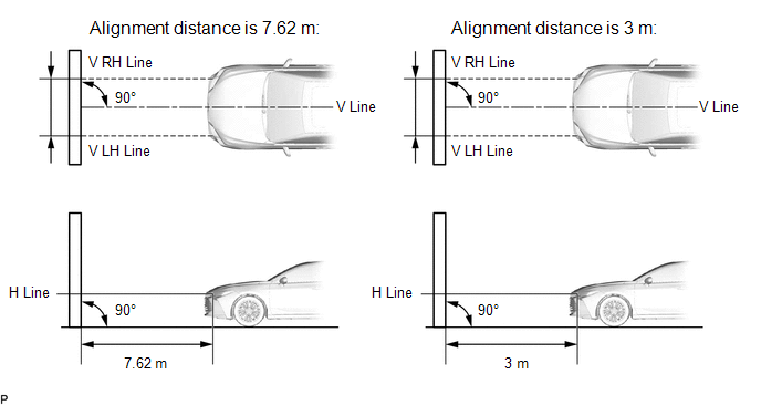
HINT:
(e) Draw base lines (H, V LH, and V RH lines) on the screen as shown in the illustration. 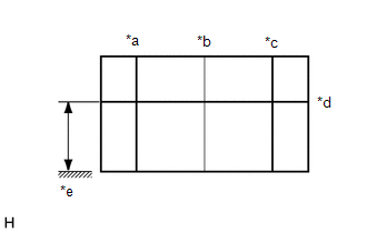
HINT: Mark the headlight center marks on the screen.
(1) H Line (Headlight height): Draw a horizontal line across the screen so that it passes through the center marks. The H line should be at the same height as the center marks of the headlights. (2) V LH Line, V RH Line (Center mark position of left-hand (LH) and right-hand (RH) headlights): Draw 2 vertical lines so that they intersect the H line at each center mark (aligned with the center marks of the headlights). 4. INSPECT HEADLIGHT AIMING (w/o Cornering Light) (a) Cover the headlight on the opposite side to prevent light from the headlight that is not being inspected from affecting the headlight aiming inspection. NOTICE: Do not keep the headlight covered for more than 3 minutes. The headlight lens is made of synthetic resin, which may melt or be damaged due to excessive heat. (b) Start the engine. (c) Turn on the headlights and check the aiming of low beam. 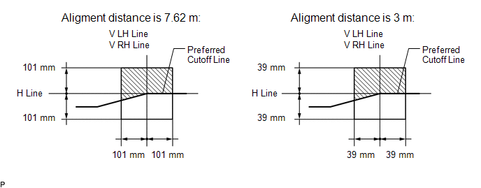
HINT:
5. INSPECT HEADLIGHT AIMING (w/ Cornering Light) (a) Cover the headlight on the opposite side to prevent light from the headlight that is not being inspected from affecting the headlight aiming inspection. NOTICE: Do not keep the headlight covered for more than 3 minutes. The headlight lens is made of synthetic resin, which may melt or be damaged due to excessive heat. (b) Start the engine. (c) Turn on the headlights and check the aiming of low beam. 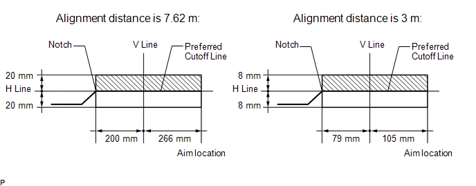
HINT:
6. ADJUST HEADLIGHT AIMING (a) Adjust the aim vertically: (1) Adjust the aim of each headlight to the specified range by turning each aiming screw with a screwdriver. 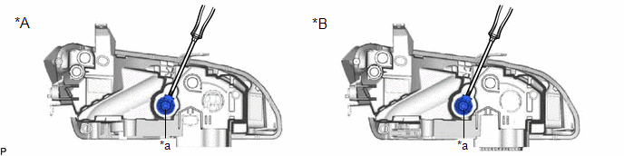
NOTICE: The final turn of the aiming screw should be made in the clockwise direction. If the screw is tightened excessively, loosen it and then retighten it, so that the final turn of the screw is in the clockwise direction. HINT:
|
Toyota Avalon (XX50) 2019-2022 Service & Repair Manual > Camshaft Oil Control Valve(for Exhaust Side Of Bank 2): Inspection
INSPECTION PROCEDURE 1. INSPECT CAMSHAFT TIMING GEAR BOLT (a) Check the stroke of the plunger in the center of the camshaft timing gear bolt. Standard Stroke: 2.2 mm (0.0866 in.) or more HINT: When pressing the plunger, there may be a stepped feeling. This is not a malfunction. If the result is not ...


