DESCRIPTION
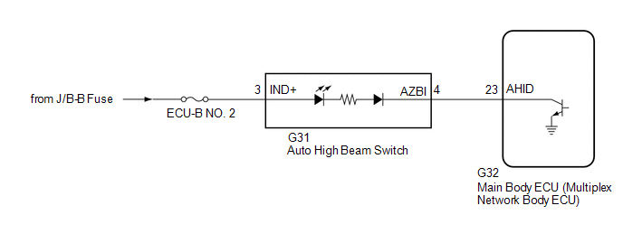
When the automatic high beam system is on, the main body ECU (multiplex network body ECU) illuminates the auto high beam switch indicator.
WIRING DIAGRAM
CAUTION / NOTICE / HINT
NOTICE:
Click here 
PROCEDURE
|
1. | PERFORM ACTIVE TEST USING TECHSTREAM |
(a) Connect the Techstream to the DLC3.
(b) Turn the engine switch on (IG).
(c) Turn the Techstream on.
(d) Enter the following menus: Body Electrical / Main Body / Active Test.
(e) Perform the Active Test according to the display on the Techstream.
Body Electrical > Main Body > Active Test|
Tester Display | Measurement Item |
Control Range | Diagnostic Note |
|---|---|---|---|
|
Automatic High Beam Switch Light |
Auto high beam switch indicator light |
OFF or ON | - |
|
Tester Display |
|---|
| Automatic High Beam Switch Light |
OK:
Auto high beam switch indicator light illuminates.
| OK |  | USE SIMULATION METHOD TO CHECK |
|
| 2. |
INSPECT AUTO HIGH BEAM SWITCH |
(a) Remove the auto high beam switch.
Click here
(b) Inspect the auto high beam switch.
Click here
| NG | | REPLACE AUTO HIGH BEAM SWITCH |
|
| 3. |
CHECK HARNESS AND CONNECTOR (POWER SOURCE - AUTO HIGH BEAM SWITCH) |
(a) Measure the voltage according to the value(s) in the table below.
Standard Voltage:
|
Tester Connection | Condition |
Specified Condition |
|---|---|---|
|
G31-3 (IND+) - Body ground |
Always | 11 to 14 V |
| NG | | REPAIR OR REPLACE HARNESS OR CONNECTOR |
|
| 4. |
CHECK HARNESS AND CONNECTOR (AUTO HIGH BEAM SWITCH - MAIN BODY ECU (MULTIPLEX NETWORK BODY ECU)) |
(a) Disconnect the G32 main body ECU (multiplex network body ECU) connector.
(b) Measure the resistance according to the value(s) in the table below.
Standard Resistance:
|
Tester Connection | Condition |
Specified Condition |
|---|---|---|
|
G31-4 (AZBI) - G32-23 (AHID) |
Always | Below 1 Ω |
|
G31-4 (AZBI) or G32-23 (AHID) - Body ground |
Always | 10 kΩ or higher |
| OK | | REPLACE MAIN BODY ECU (MULTIPLEX NETWORK BODY ECU) |
| NG | | REPAIR OR REPLACE HARNESS OR CONNECTOR |
DESCRIPTION
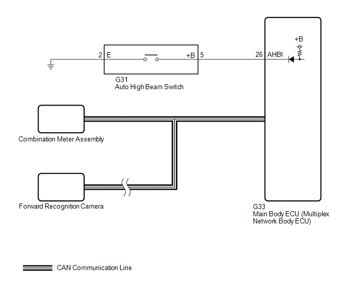
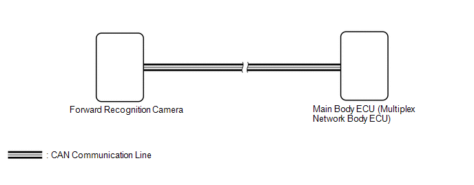
The main body ECU (multiplex network body ECU) controls the automatic high beam system based on signals received from the forward recognition camera.
WIRING DIAGRAM
CAUTION / NOTICE / HINT
NOTICE:
Click here 
Click here
Click here
PROCEDURE
|
1. | READ VALUE USING TECHSTREAM |
(a) Connect the Techstream to the DLC3.
(b) Turn the engine switch on (IG).
(c) Turn the Techstream on.
(d) Enter the following menus: Chassis / Front Recognition Camera / Data List.
(e) Read the Data List according to the display on the Techstream.
Chassis > Front Recognition Camera > Data List|
Tester Display | Measurement Item |
Range | Normal Condition |
Diagnostic Note |
|---|---|---|---|---|
|
High Temperature Status1 |
High temperature malfunction status |
OFF or ON | OFF: Forward recognition camera high temperature malfunction does not exist ON: Forward recognition camera high temperature malfunction exists |
- |
|
Tester Display |
|---|
| High Temperature Status1 |
OK:
"OFF" is displayed on the Techstream.
HINT:
If "ON" is displayed, move the vehicle to a cool place and allow the temperature of the forward recognition camera to decrease before continuing with troubleshooting.
| NG |  |
END (TEMPORARY SUSPENSION OF AUTOMATIC HIGH BEAM SYSTEM DUE TO HIGH FORWARD RECOGNITION CAMERA TEMPERATURE) |
|
| 2. |
CHECK AUTOMATIC HIGH BEAM INDICATOR LIGHT |
(a) Check the operation of the automatic high beam indicator light.
(1) Turn the engine switch on (IG).
(2) Turn the light control switch to the AUTO or head position.
(3) Cover the automatic light control sensor to turn the low beam headlights on.
(4) Move the dimmer switch to the high position.
(5) Press the auto high beam switch.
|
Result | Proceed to |
|---|---|
|
OK (The automatic high beam indicator light and the auto high beam switch indicator illuminate) |
A |
| NG (Automatic high beam indicator light does not illuminate) |
B |
| NG (Auto high beam switch indicator does not illuminate) |
C |
| NG (Automatic high beam indicator light and auto high beam switch indicator do not operate) |
D |
| B |
| GO TO STEP 5 |
| C |
| GO TO OTHER PROBLEM (Proceed to Automatic High Beam Switch Indicator does not Come ON) |
| D |
| GO TO STEP 6 |
|
| 3. |
READ VALUE USING TECHSTREAM |
|
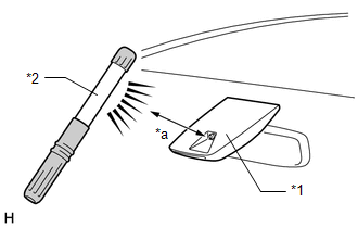
*1 | Forward Recognition Camera (Automatic High Beam Sensor) |
|
*2 | Work Light or Equivalent |
|
*a | 100 mm or less |
(a) Shine a light on the automatic high beam sensor.
HINT:
If troubleshooting is being performed in a bright area, such as outside on a sunny day, it will not be necessary to perform this step.
(b) Connect the Techstream to the DLC3.
(c) Turn the engine switch on (IG).
(d) Turn the Techstream on.
(e) Enter the following menus: Body Electrical / Main Body / Data List.
(f) Read the Data List according to the display on the Techstream.
HINT:
As it may take time for the values in the Data List to change, wait at least 10 seconds before reading the Data List.
Body Electrical > Main Body > Data List|
Tester Display | Measurement Item |
Range | Normal Condition |
Diagnostic Note |
|---|---|---|---|---|
|
Auto H Beam STS0 | Automatic high beam sensor current state |
Undetec, CAM NA, No sens, Hlight, Taillgt, Speed, Daytime, Village, Malfunc, Delay, Aim Lmt, SAE Mod, Undefin or LIN Err |
Condition can be displayed |
- |
|
Tester Display |
|---|
| Auto H Beam STS0 |
OK:
"Daytime" is displayed on the Techstream.
| NG | | REPLACE FORWARD RECOGNITION CAMERA |
|
| 4. |
READ VALUE USING TECHSTREAM |
|
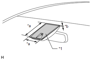
*1 | Cardboard or Equivalent Object |
|
*a | 150 mm or more |
|
*b | 3 mm or more |
(a) Cover the automatic high beam sensor with an opaque object, such as cardboard.
NOTICE:
(b) Connect the Techstream to the DLC3.
(c) Turn the engine switch on (IG).
(d) Turn the Techstream on.
(e) Enter the following menus: Body Electrical / Main Body / Data List.
(f) Read the Data List according to the display on the Techstream.
HINT:
As it may take time for the values in the Data List to change, wait at least 10 seconds before reading the Data List.
Body Electrical > Main Body > Data List|
Tester Display | Measurement Item |
Range | Normal Condition |
Diagnostic Note |
|---|---|---|---|---|
|
Auto H Beam STS0 | Automatic high beam sensor current state |
Undetec, CAM NA, No sens, Hlight, Taillgt, Speed, Daytime, Village, Malfunc, Delay, Aim Lmt, SAE Mod, Undefin or LIN Err |
Condition can be displayed |
- |
|
Tester Display |
|---|
| Auto H Beam STS0 |
OK:
"Speed" is displayed on the Techstream.
| OK | | USE SIMULATION METHOD TO CHECK |
| NG | | REPLACE FORWARD RECOGNITION CAMERA |
| 5. |
PERFORM ACTIVE TEST USING TECHSTREAM |
(a) Connect the Techstream to the DLC3.
(b) Turn the engine switch on (IG).
(c) Turn the Techstream on.
(d) Enter the following menus: Body Electrical / Combination Meter / Active Test.
(e) Perform the Active Test according to the display on the Techstream.
Body Electrical > Combination Meter > Active Test|
Tester Display | Measurement Item |
Control Range | Diagnostic Note |
|---|---|---|---|
|
Multi Display All (White) |
Multi-information display (White display) |
OFF or ON | - |
|
Tester Display |
|---|
| Multi Display All (White) |
OK:
The multi-information display in the combination meter assembly turns on according to the operation of the Active Test.
| OK | | REPLACE MAIN BODY ECU (MULTIPLEX NETWORK BODY ECU) |
| NG | | REPLACE COMBINATION METER ASSEMBLY |
| 6. |
READ VALUE USING TECHSTREAM |
(a) Connect the Techstream to the DLC3.
(b) Turn the engine switch on (IG).
(c) Turn the Techstream on.
(d) Enter the following menus: Body Electrical / Main Body / Data List.
(e) Read the Data List according to the display on the Techstream.
Body Electrical > Main Body > Data List|
Tester Display | Measurement Item |
Range | Normal Condition |
Diagnostic Note |
|---|---|---|---|---|
|
Auto High Beam Main Switch |
Auto high beam switch signal |
OFF or ON | OFF: Auto high beam switch not pressed ON: Auto high beam switch pressed |
- |
|
Tester Display |
|---|
| Auto High Beam Main Switch |
OK:
Normal conditions listed above are displayed.
| NG | | GO TO STEP 8 |
|
| 7. |
READ VALUE USING TECHSTREAM |
(a) Connect the Techstream to the DLC3.
(b) Turn the engine switch on (IG).
(c) Turn the Techstream on.
(d) Enter the following menus: Body Electrical / Main Body / Data List.
(e) Read the Data List according to the display on the Techstream.
Body Electrical > Main Body > Data List|
Tester Display | Measurement Item |
Range | Normal Condition |
Diagnostic Note |
|---|---|---|---|---|
|
Auto H Beam STS0 | Automatic high beam sensor current state |
Undetec, CAM NA, No sens, Hlight, Taillgt, Speed, Daytime, Village, Malfunc, Delay, Aim Lmt, SAE Mod, Undefin or LIN Err |
Condition can be displayed |
- |
|
Tester Display |
|---|
| Auto H Beam STS0 |
OK:
"Daytime" or "Speed" is displayed on the Techstream.
| OK | | REPLACE MAIN BODY ECU (MULTIPLEX NETWORK BODY ECU) |
| NG | | REPLACE FORWARD RECOGNITION CAMERA |
| 8. |
INSPECT AUTO HIGH BEAM SWITCH |
(a) Remove the auto high beam switch.
Click here
(b) Inspect the auto high beam switch.
Click here
| NG | | REPLACE AUTO HIGH BEAM SWITCH |
|
| 9. |
CHECK HARNESS AND CONNECTOR (AUTO HIGH BEAM SWITCH - MAIN BODY ECU (MULTIPLEX NETWORK BODY ECU) AND BODY GROUND) |
(a) Disconnect the G33 main body ECU (multiplex network body ECU) connector.
(b) Measure the resistance according to the value(s) in the table below.
Standard Resistance:
|
Tester Connection | Condition |
Specified Condition |
|---|---|---|
|
G31-5 (+B) - G33-26 (AHBI) |
Always | Below 1 Ω |
|
G31-5 (+B) or G33-26 (AHBI) - Body ground |
Always | 10 kΩ or higher |
|
G31-2 (E) - Body ground |
Always | Below 1 Ω |
| OK | | REPLACE MAIN BODY ECU (MULTIPLEX NETWORK BODY ECU) |
| NG | | REPAIR OR REPLACE HARNESS OR CONNECTOR |
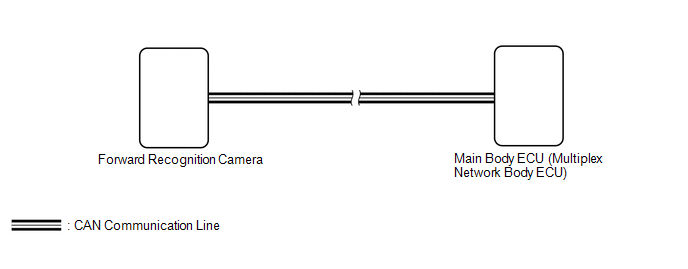
DESCRIPTION
The main body ECU (multiplex network body ECU) determines the status of the automatic high beam system based on the automatic high beam system signal from the forward recognition camera.
|
DTC No. | Detection Item |
DTC Detection Condition | Trouble Area |
DTC Output from |
|---|---|---|---|---|
|
B124B | Automatic High Beam System |
Malfunction in automatic high beam system |
| Main body ECU (multiplex network body ECU) |
WIRING DIAGRAM
CAUTION / NOTICE / HINT
NOTICE:
Click here 
Click here
HINT:
If the forward recognition camera stores a DTC for a malfunction of any of the following, this DTC will be stored simultaneously.PROCEDURE
|
1. | CHECK FOR DTC (HEALTH CHECK) |
(a) Connect the Techstream to the DLC3.
(b) Turn the engine switch on (IG).
(c) Turn the Techstream on.
(d) Enter the following menus: System Select / Health Check.
(e) Check for DTCs.
|
Result | Proceed to |
|---|---|
|
Only DTC B124B is output |
A |
| DTC B124B and other DTCs are output |
B |
| B |
 | GO TO OTHER DTC CHART |
|
| 2. |
CHECK FRONT CAMERA SYSTEM |
(a) Check if a dynamic radar cruise control system, lane departure alert system or pre-collision system warning message is displayed on the multi-information display.
Click here
OK:
No dynamic radar cruise control system, lane departure alert system and pre-collision system warning messages are displayed.
| OK | | REPLACE MAIN BODY ECU (MULTIPLEX NETWORK BODY ECU) |
| NG | | GO TO FRONT CAMERA SYSTEM |
DESCRIPTION
The main body ECU (multiplex network body ECU) detects a high beam headlight illumination request signal of the automatic high beam system from the forward recognition camera.
|
DTC No. | Detection Item |
DTC Detection Condition | Trouble Area |
DTC Output from |
|---|---|---|---|---|
|
B124C | Automatic High Beam Camera |
Malfunction in forward recognition camera |
Front camera system | Main body ECU (multiplex network body ECU) |
WIRING DIAGRAM
PROCEDURE
| 1. |
CHECK FRONT CAMERA SYSTEM |
(a) Check front camera system.
Click here 
| NEXT |  | END |
DESCRIPTION
The headlight ECU sub-assembly LH or headlight ECU sub-assembly RH stores a DTC if it detects an internal malfunction.
|
DTC No. | Detection Item |
DTC Detection Condition | Trouble Area |
DTC Output from |
|---|---|---|---|---|
|
B242C | Right Headlight ECU Malfunction |
| Headlight ECU sub-assembly RH |
Headlight ECU sub-assembly RH |
|
B242D | Left Headlight ECU Malfunction |
| Headlight ECU sub-assembly LH |
Headlight ECU sub-assembly LH |
CAUTION / NOTICE / HINT
NOTICE:
If the headlight ECU sub-assembly LH has been replaced, it is necessary to synchronize the vehicle information the headlight ECU sub-assembly LH.
Click here

PROCEDURE
| 1. |
CLEAR DTC |
(a) Connect the Techstream to the DLC3.
(b) Turn the engine switch on (IG).
(c) Turn the Techstream on.
(d) Enter the following menus: Body Electrical / HL AutoLeveling or HL AutoLeveling (Sub) / Trouble Codes.
(e) Clear the DTCs.
Body Electrical > HL AutoLeveling > Clear DTCs Body Electrical > HL AutoLeveling (Sub) > Clear DTCs
|
| 2. |
CHECK FOR DTC |
(a) Connect the Techstream to the DLC3.
(b) Turn the engine switch on (IG).
(c) Wait for at least maximum 15 minutes.
(d) Turn the Techstream on.
(e) Enter the following menus: Body Electrical / HL AutoLeveling or HL AutoLeveling (Sub) / Trouble Codes.
(f) Check for DTCs.
Body Electrical > HL AutoLeveling > Trouble Codes Body Electrical > HL AutoLeveling (Sub) > Trouble CodesOK:
DTC B242C and B242D are not output.
|
Result | Proceed to |
|---|---|
|
OK | A |
|
NG (DTC B242C is output) |
B |
| NG (DTC B242D is output) |
C |
| A |
 | USE SIMULATION METHOD TO CHECK |
| B |
| REPLACE HEADLIGHT ECU SUB-ASSEMBLY RH |
| C |
| REPLACE HEADLIGHT ECU SUB-ASSEMBLY LH |
DESCRIPTION
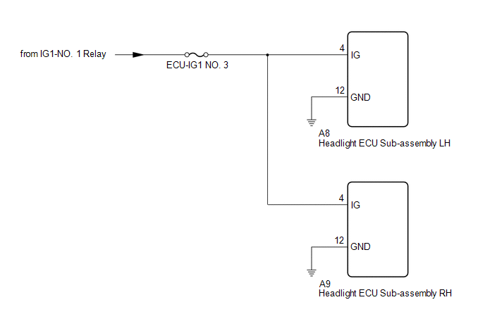
The headlight ECU sub-assembly operates using the power source voltage input from the IG terminal and ECUB terminal.
The IG terminal power source voltage is supplied by turning the IG1-NO. 1 relay to ON.
The headlight ECU sub-assembly receives engine switch on (IG) signals from the main body ECU (multiplex network body ECU) via CAN communication, compares the engine switch on (IG) signal and the power source voltage supply condition of the IG terminal and monitors the result.
HL AutoLeveling|
DTC No. | Detection Item |
DTC Detection Condition | Trouble Area |
DTC Output from |
|---|---|---|---|---|
|
B242E | Open in IG Circuit |
|
| Headlight ECU sub-assembly LH |
|
DTC No. | Detection Item |
DTC Detection Condition | Trouble Area |
DTC Output from |
|---|---|---|---|---|
|
B242E | Open in IG Circuit |
|
| Headlight ECU sub-assembly RH |
WIRING DIAGRAM
CAUTION / NOTICE / HINT
NOTICE:
Click here 
PROCEDURE
|
1. | CLEAR DTC |
(a) Connect the Techstream to the DLC3.
(b) Turn the engine switch on (IG).
(c) Turn the Techstream on.
(d) Enter the following menus: Body Electrical / HL AutoLeveling or HL AutoLeveling (Sub) / Trouble Codes.
(e) Clear the DTCs.
Body Electrical > HL AutoLeveling > Clear DTCs Body Electrical > HL AutoLeveling (Sub) > Clear DTCs
|
| 2. |
CHECK FOR DTC |
(a) Connect the Techstream to the DLC3.
(b) Turn the engine switch on (IG).
(c) Wait 10 seconds or more.
(d) Turn the Techstream on.
(e) Enter the following menus: Body Electrical / HL AutoLeveling or HL AutoLeveling (Sub) / Trouble Codes.
(f) Check for DTCs.
Body Electrical > HL AutoLeveling > Trouble Codes Body Electrical > HL AutoLeveling (Sub) > Trouble CodesOK:
DTC B242E is not output.
|
Result | Proceed to |
|---|---|
|
OK | A |
|
NG (DTC output from headlight ECU sub-assembly LH) |
B |
| NG (DTC output from headlight ECU sub-assembly RH) |
C |
| A |
 | USE SIMULATION METHOD TO CHECK |
| C |
| GO TO STEP 5 |
|
| 3. |
INSPECT HEADLIGHT ECU SUB-ASSEMBLY LH (IG TERMINAL VOLTAGE) |

|
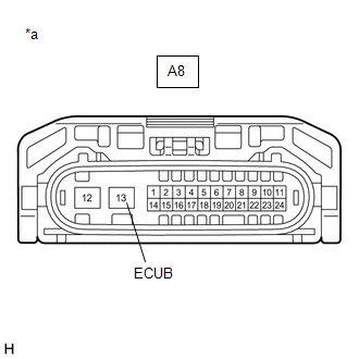
*a | Front view of wire harness connector (to Headlight ECU Sub-assembly LH) |
(a) Disconnect the A8 headlight ECU sub-assembly LH connector.
(b) Measure the voltage according to the value(s) in the table below.
Standard Voltage:
|
Tester Connection | Condition |
Specified Condition |
|---|---|---|
|
A8-4 (IG) - Body ground |
Engine switch on (IG) |
11 to 14 V |
| NG | | REPAIR OR REPLACE HARNESS OR CONNECTOR |
|
| 4. |
CHECK HARNESS AND CONNECTOR (HEADLIGHT ECU SUB-ASSEMBLY LH - BODY GROUND) |
(a) Measure the resistance according to the value(s) in the table below.
Standard Resistance:
|
Tester Connection | Condition |
Specified Condition |
|---|---|---|
|
A8-12 (GND) - Body ground |
Always | Below 1 Ω |
| OK | | REPLACE HEADLIGHT ECU SUB-ASSEMBLY LH |
| NG | | REPAIR OR REPLACE HARNESS OR CONNECTOR |
| 5. |
INSPECT HEADLIGHT ECU SUB-ASSEMBLY RH (IG TERMINAL VOLTAGE) |
|
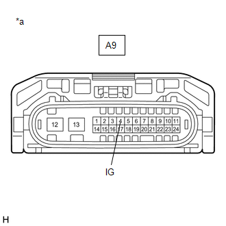
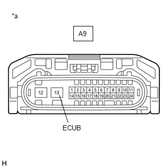
*a | Front view of wire harness connector (to Headlight ECU Sub-assembly RH) |
(a) Disconnect the A9 headlight ECU sub-assembly RH connector.
(b) Measure the voltage according to the value(s) in the table below.
Standard Voltage:
|
Tester Connection | Condition |
Specified Condition |
|---|---|---|
|
A9-4 (IG) - Body ground |
Engine switch on (IG) |
11 to 14 V |
| NG | | REPAIR OR REPLACE HARNESS OR CONNECTOR |
|
| 6. |
CHECK HARNESS AND CONNECTOR (HEADLIGHT ECU SUB-ASSEMBLY RH - BODY GROUND) |
(a) Measure the resistance according to the value(s) in the table below.
Standard Resistance:
|
Tester Connection | Condition |
Specified Condition |
|---|---|---|
|
A9-12 (GND) - Body ground |
Always | Below 1 Ω |
| OK | | REPLACE HEADLIGHT ECU SUB-ASSEMBLY RH |
| NG | | REPAIR OR REPLACE HARNESS OR CONNECTOR |
DESCRIPTION
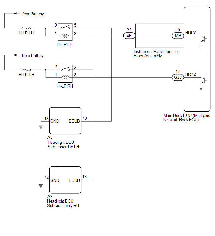
The headlight ECU sub-assembly operates using the power source voltage input from the IG terminal and ECUB terminal.
The power source voltage of the ECUB terminal is supplied when the main body ECU (multiplex network body ECU) turns the ECUB power supply relay (H-LP LH relay and H-LP RH relay) to ON.
The headlight ECU sub-assembly compares the power source voltage supply condition of the IG terminal and ECUB terminal and monitors the result.
HL AutoLeveling|
DTC No. | Detection Item |
DTC Detection Condition | Trouble Area |
DTC Output from |
|---|---|---|---|---|
|
B242F | Open in B Power Line |
|
| Headlight ECU sub-assembly LH |
|
DTC No. | Detection Item |
DTC Detection Condition | Trouble Area |
DTC Output from |
|---|---|---|---|---|
|
B242F | Open in B Power Line |
|
| Headlight ECU sub-assembly RH |
WIRING DIAGRAM
CAUTION / NOTICE / HINT
NOTICE:
Click here 
Click here
PROCEDURE
|
1. | CLEAR DTC |
(a) Connect the Techstream to the DLC3.
(b) Turn the engine switch on (IG).
(c) Turn the Techstream on.
(d) Enter the following menus: Body Electrical / HL AutoLeveling or HL AutoLeveling (Sub) / Trouble Codes.
(e) Clear the DTCs.
Body Electrical > HL AutoLeveling > Clear DTCs Body Electrical > HL AutoLeveling (Sub) > Clear DTCs
|
| 2. |
CHECK FOR DTC |
(a) Connect the Techstream to the DLC3.
(b) Turn the engine switch on (IG).
(c) Wait 10 seconds or more.
(d) Turn the Techstream on.
(e) Enter the following menus: Body Electrical / HL AutoLeveling or HL AutoLeveling (Sub) / Trouble Codes.
(f) Check for DTCs.
Body Electrical > HL AutoLeveling > Trouble Codes Body Electrical > HL AutoLeveling (Sub) > Trouble CodesOK:
DTC B242F is not output.
|
Result | Proceed to |
|---|---|
|
OK | A |
|
NG (DTC output from headlight ECU sub-assembly LH) |
B |
| NG (DTC output from headlight ECU sub-assembly RH) |
C |
| A |
 | USE SIMULATION METHOD TO CHECK |
| C |
| GO TO STEP 10 |
|
| 3. |
INSPECT HEADLIGHT ECU SUB-ASSEMBLY LH (ECUB TERMINAL VOLTAGE) |
|
*a | Front view of wire harness connector (to Headlight ECU Sub-assembly LH) |
(a) Disconnect the A8 headlight ECU sub-assembly LH connector.
(b) Measure the voltage according to the value(s) in the table below.
Standard Voltage:
|
Tester Connection | Condition |
Specified Condition |
|---|---|---|
|
A8-13 (ECUB) - Body ground |
Engine switch on (IG) |
9.5 to 14 V |
| NG | | GO TO STEP 5 |
|
| 4. |
CHECK HARNESS AND CONNECTOR (HEADLIGHT ECU SUB-ASSEMBLY LH - BODY GROUND) |
(a) Measure the resistance according to the value(s) in the table below.
Standard Resistance:
|
Tester Connection | Condition |
Specified Condition |
|---|---|---|
|
A8-12 (GND) - Body ground |
Always | Below 1 Ω |
| OK | | REPLACE HEADLIGHT ECU SUB-ASSEMBLY LH |
| NG | | REPAIR OR REPLACE HARNESS OR CONNECTOR |
| 5. |
INSPECT H-LP LH RELAY |
(a) Inspect the H-LP LH relay.
Click here
| NG | | REPLACE H-LP LH RELAY |
|
| 6. |
CHECK HARNESS AND CONNECTOR (H-LP LH RELAY - HEADLIGHT ECU SUB-ASSEMBLY LH) |
(a) Measure the resistance according to the value(s) in the table below.
Standard Resistance:
|
Tester Connection | Condition |
Specified Condition |
|---|---|---|
|
5 (H-LP LH relay) - A8-13 (ECUB) |
Always | Below 1 Ω |
|
5 (H-LP LH relay) or A8-13 (ECUB) - Body ground |
Always | 10 kΩ or higher |
| NG | | REPAIR OR REPLACE HARNESS OR CONNECTOR |
|
| 7. |
CHECK HARNESS AND CONNECTOR (POWER SOURCE - H-LP LH RELAY) |
(a) Measure the voltage according to the value(s) in the table below.
Standard Voltage:
|
Tester Connection | Condition |
Specified Condition |
|---|---|---|
|
1 (H-LP LH relay) - Body ground |
Always | 11 to 14 V |
|
3 (H-LP LH relay) - Body ground |
Always | 11 to 14 V |
| NG | | REPAIR OR REPLACE HARNESS OR CONNECTOR |
|
| 8. |
CHECK HARNESS AND CONNECTOR (H-LP LH RELAY - INSTRUMENT PANEL JUNCTION BLOCK ASSEMBLY) |
(a) Disconnect the 4F instrument panel junction block assembly connector.
(b) Measure the resistance according to the value(s) in the table below.
Standard Resistance:
|
Tester Connection | Condition |
Specified Condition |
|---|---|---|
|
2 (H-LP LH relay) - 4F-31 |
Always | Below 1 Ω |
|
2 (H-LP LH relay) or 4F-31 - Body ground |
Always | 10 kΩ or higher |
| NG | | REPAIR OR REPLACE HARNESS OR CONNECTOR |
|
| 9. |
INSPECT INSTRUMENT PANEL JUNCTION BLOCK ASSEMBLY |
|
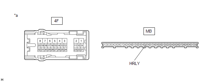
*a | Component without harness connected (Instrument Panel Junction Block Assembly) |
- | - |
(a) Remove the main body ECU (multiplex network body ECU) from the instrument panel junction block assembly.
Click here
(b) Measure the resistance according to the value(s) in the table below.
Standard Resistance:
|
Tester Connection | Condition |
Specified Condition |
|---|---|---|
|
4F-31 - MB-15 (HRLY) |
Always | Below 1 Ω |
| OK | | REPLACE MAIN BODY ECU (MULTIPLEX NETWORK BODY ECU) |
| NG | | REPLACE INSTRUMENT PANEL JUNCTION BLOCK ASSEMBLY |
| 10. |
INSPECT HEADLIGHT ECU SUB-ASSEMBLY RH (ECUB TERMINAL VOLTAGE) |
|
*a | Front view of wire harness connector (to Headlight ECU Sub-assembly RH) |
(a) Disconnect the A9 headlight ECU sub-assembly RH connector.
(b) Measure the voltage according to the value(s) in the table below.
Standard Voltage:
|
Tester Connection | Condition |
Specified Condition |
|---|---|---|
|
A9-13 (ECUB) - Body ground |
Engine switch on (IG) |
9.5 to 14 V |
| NG | | GO TO STEP 12 |
|
| 11. |
CHECK HARNESS AND CONNECTOR (HEADLIGHT ECU SUB-ASSEMBLY RH - BODY GROUND) |
(a) Measure the resistance according to the value(s) in the table below.
Standard Resistance:
|
Tester Connection | Condition |
Specified Condition |
|---|---|---|
|
A9-12 (GND) - Body ground |
Always | Below 1 Ω |
| OK | | REPLACE HEADLIGHT ECU SUB-ASSEMBLY RH |
| NG | | REPAIR OR REPLACE HARNESS OR CONNECTOR |
| 12. |
INSPECT H-LP RH RELAY |
(a) Inspect the H-LP RH relay.
Click here
| NG | | REPLACE H-LP RH RELAY |
|
| 13. |
CHECK HARNESS AND CONNECTOR (H-LP RH RELAY - HEADLIGHT ECU SUB-ASSEMBLY RH) |
(a) Measure the resistance according to the value(s) in the table below.
Standard Resistance:
|
Tester Connection | Condition |
Specified Condition |
|---|---|---|
|
5 (H-LP RH relay) - A9-13 (ECUB) |
Always | Below 1 Ω |
|
5 (H-LP RH relay) or A9-13 (ECUB) - Body ground |
Always | 10 kΩ or higher |
| NG | | REPAIR OR REPLACE HARNESS OR CONNECTOR |
|
| 14. |
CHECK HARNESS AND CONNECTOR (POWER SOURCE - H-LP RH RELAY) |
(a) Measure the voltage according to the value(s) in the table below.
Standard Voltage:
|
Tester Connection | Condition |
Specified Condition |
|---|---|---|
|
1 (H-LP RH relay) - Body ground |
Always | 11 to 14 V |
|
3 (H-LP RH relay) - Body ground |
Always | 11 to 14 V |
| NG | | REPAIR OR REPLACE HARNESS OR CONNECTOR |
|
| 15. |
CHECK HARNESS AND CONNECTOR (H-LP RH RELAY - MAIN BODY ECU (MULTIPLEX NETWORK BODY ECU)) |
(a) Disconnect the G33 main body ECU (multiplex network body ECU) connector.
(b) Measure the resistance according to the value(s) in the table below.
Standard Resistance:
|
Tester Connection | Condition |
Specified Condition |
|---|---|---|
|
2 (H-LP RH relay) - G33-12 (HRY2) |
Always | Below 1 Ω |
|
2 (H-LP RH relay) or G33-12 (HRY2) - Body ground |
Always | 10 kΩ or higher |
| OK | | REPLACE MAIN BODY ECU (MULTIPLEX NETWORK BODY ECU) |
| NG | | REPAIR OR REPLACE HARNESS OR CONNECTOR |
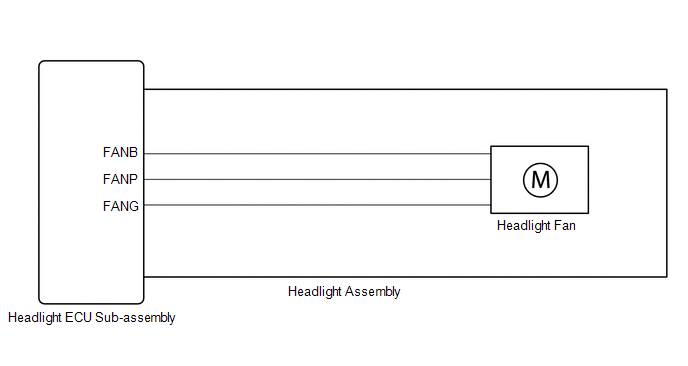
DESCRIPTION
The headlight ECU sub-assembly operates the low beam fan to cool the headlight LED unit in order to prevent the headlight LED unit from overheating.
Illuminates the low beam headlights and continuously operates the low beam fan.
The headlight ECU sub-assembly monitors the pulse signals from the FANP terminal when the low beam fans are operating.
HINT:
If B243D or B243E is output, the headlight ECU sub-assembly performs low beam headlight dimming control.
|
DTC No. | Detection Item |
DTC Detection Condition | Trouble Area |
DTC Output from |
|---|---|---|---|---|
|
B243D | Left Low Beam Fan Malfunction |
|
| Headlight ECU sub-assembly LH |
|
B243E | Right Low Beam Fan Malfunction |
|
| Headlight ECU sub-assembly RH |
WIRING DIAGRAM
CAUTION / NOTICE / HINT
NOTICE:
Click here 
Click here
PROCEDURE
|
1. | CLEAR DTC |
(a) Connect the Techstream to the DLC3.
(b) Turn the engine switch on (IG).
(c) Turn the Techstream on.
(d) Enter the following menus: Body Electrical / HL AutoLeveling or HL AutoLeveling (Sub) / Trouble Codes.
(e) Clear the DTCs.
Body Electrical > HL AutoLeveling > Clear DTCs Body Electrical > HL AutoLeveling (Sub) > Clear DTCs
|
| 2. |
CHECK FOR DTC |
(a) Connect the Techstream to the DLC3.
(b) Turn the engine switch on (IG).
(c) Operate the light control switch to turn on the low beam headlights and wait 4 seconds or more.
(d) Turn the Techstream on.
(e) Enter the following menus: Body Electrical / HL AutoLeveling or HL AutoLeveling (Sub) / Trouble Codes.
(f) Check for DTCs.
Body Electrical > HL AutoLeveling > Trouble Codes Body Electrical > HL AutoLeveling (Sub) > Trouble CodesOK:
DTC B243D and B243E are not output.
|
Result | Proceed to |
|---|---|
|
OK | A |
|
NG (DTC B243D is output) |
B |
| NG (DTC B243E is output) |
C |
| A |
 | USE SIMULATION METHOD TO CHECK |
| C |
| GO TO STEP 6 |
|
| 3. |
CHECK HEADLIGHT ASSEMBLY LH |
(a) Remove each headlight ECU sub-assembly, interchange the headlight assembly LH with RH and connect the connectors.
Click here
|
| 4. |
CLEAR DTC |
(a) Connect the Techstream to the DLC3.
(b) Turn the engine switch on (IG).
(c) Turn the Techstream on.
(d) Enter the following menus: Body Electrical / HL AutoLeveling or HL AutoLeveling (Sub) / Trouble Codes.
(e) Clear the DTCs.
Body Electrical > HL AutoLeveling > Clear DTCs Body Electrical > HL AutoLeveling (Sub) > Clear DTCs
|
| 5. |
CHECK FOR DTC |
(a) Connect the Techstream to the DLC3.
(b) Turn the engine switch on (IG).
(c) Operate the light control switch to turn on the low beam headlights and wait 4 seconds or more.
(d) Turn the Techstream on.
(e) Enter the following menus: Body Electrical / HL AutoLeveling or HL AutoLeveling (Sub) / Trouble Codes.
(f) Check for DTCs.
Body Electrical > HL AutoLeveling > Trouble Codes Body Electrical > HL AutoLeveling (Sub) > Trouble Codes|
Result | Proceed to |
|---|---|
|
DTC B243D is output | A |
|
DTC B243E is output | B |
| A |
| REPLACE HEADLIGHT ECU SUB-ASSEMBLY LH |
| B |
| REPLACE HEADLIGHT ASSEMBLY LH |
| 6. |
CHECK HEADLIGHT ASSEMBLY RH |
(a) Remove each headlight ECU sub-assembly, interchange the headlight assembly RH with LH and connect the connectors.
Click here
|
| 7. |
CLEAR DTC |
(a) Connect the Techstream to the DLC3.
(b) Turn the engine switch on (IG).
(c) Turn the Techstream on.
(d) Enter the following menus: Body Electrical / HL AutoLeveling or HL AutoLeveling (Sub) / Trouble Codes.
(e) Clear the DTCs.
Body Electrical > HL AutoLeveling > Clear DTCs Body Electrical > HL AutoLeveling (Sub) > Clear DTCs
|
| 8. |
CHECK FOR DTC |
(a) Connect the Techstream to the DLC3.
(b) Turn the engine switch on (IG).
(c) Operate the light control switch to turn on the low beam headlights and wait 4 seconds or more.
(d) Turn the Techstream on.
(e) Enter the following menus: Body Electrical / HL AutoLeveling or HL AutoLeveling (Sub) / Trouble Codes.
(f) Check for DTCs.
Body Electrical > HL AutoLeveling > Trouble Codes Body Electrical > HL AutoLeveling (Sub) > Trouble Codes|
Result | Proceed to |
|---|---|
|
DTC B243E is output | A |
|
DTC B243D is output | B |
| A |
| REPLACE HEADLIGHT ECU SUB-ASSEMBLY RH |
| B |
| REPLACE HEADLIGHT ASSEMBLY RH |
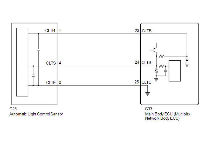
DESCRIPTION
The automatic light control sensor detects ambient light. The sensor creates an electrical signal based on the amount of light detected, and sends the signal to the main body ECU (multiplex network body ECU). The main body ECU (multiplex network body ECU) turns on or off the headlights and taillights according to the signal.
|
DTC No. | Detection Item |
DTC Detection Condition | Trouble Area |
DTC Output from |
|---|---|---|---|---|
|
B1244 | Light Sensor Circuit |
|
| Main body ECU (multiplex network body ECU) |
WIRING DIAGRAM
CAUTION / NOTICE / HINT
NOTICE:
Before replacing the main body ECU (multiplex network body ECU), refer to Registration.
Click here 
PROCEDURE
| 1. |
CLEAR DTC |
(a) Connect the Techstream to the DLC3.
(b) Turn the engine switch on (IG).
(c) Turn the Techstream on.
(d) Enter the following menus: Body Electrical / Main Body / Trouble Codes.
(e) Clear the DTCs.
Body Electrical > Main Body > Clear DTCs
|
| 2. |
CHECK FOR DTC |
(a) Connect the Techstream to the DLC3.
(b) Turn the engine switch on (IG).
(c) Wait 10 seconds or more.
(d) Turn the Techstream on.
(e) Enter the following menus: Body Electrical / Main Body / Trouble Codes.
(f) Check for DTCs.
Body Electrical > Main Body > Trouble CodesOK:
DTC B1244 is not output.
| OK |  |
USE SIMULATION METHOD TO CHECK |
|
| 3. |
READ VALUE USING TECHSTREAM |
(a) Connect the Techstream to the DLC3.
(b) Turn the engine switch on (IG).
(c) Turn the Techstream on.
(d) Enter the following menus: Body Electrical / Main Body / Data List.
(e) According to the display on the Techstream, read the Data List and check that the value of Light Sensor Illuminance changes while performing the following:
(1) Cover the automatic light control sensor with an opaque object.
(2) Slowly move the opaque object to uncover and then cover the automatic light control sensor.
Body Electrical > Main Body > Data List|
Tester Display | Measurement Item |
Range | Normal Condition |
Diagnostic Note |
|---|---|---|---|---|
|
Light Sensor Illuminance |
Light control sensor illuminance |
0 to 8191 lx or SensorFail |
Value is output according to ambient light level |
- |
|
Tester Display |
|---|
| Light Sensor Illuminance |
OK:
The value changes according to the amount the automatic light control sensor is covered.
| OK | | REPLACE MAIN BODY ECU (MULTIPLEX NETWORK BODY ECU) |
|
| 4. |
CHECK HARNESS AND CONNECTOR (AUTOMATIC LIGHT CONTROL SENSOR - MAIN BODY ECU (MULTIPLEX NETWORK BODY ECU)) |
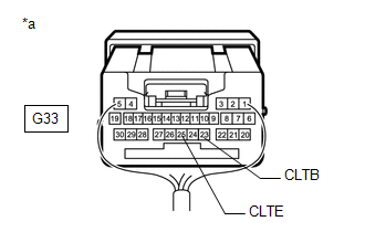
(a) Disconnect the G23 automatic light control sensor connector.
(b) Disconnect the G33 main body ECU (multiplex network body ECU) connector.
(c) Measure the resistance according to the value(s) in the table below.
Standard Resistance:
|
Tester Connection | Condition |
Specified Condition |
|---|---|---|
|
G23-1 (CLTB) - G33-23 (CLTB) |
Always | Below 1 Ω |
|
G23-4 (CLTS) - G33-24 (CLTS) |
Always | Below 1 Ω |
|
G23-2 (CLTE) - G33-25 (CLTE) |
Always | Below 1 Ω |
|
G23-1 (CLTB) or G33-23 (CLTB) - Body ground |
Always | 10 kΩ or higher |
|
G23-4 (CLTS) or G33-24 (CLTS) - Body ground |
Always | 10 kΩ or higher |
|
G23-2 (CLTE) or G33-25 (CLTE) - Body ground |
Always | 10 kΩ or higher |
| NG | | REPAIR OR REPLACE HARNESS OR CONNECTOR |
|
| 5. |
INSPECT MAIN BODY ECU (MULTIPLEX NETWORK BODY ECU) |
|
*a | Component with harness connected (Main Body ECU (Multiplex Network Body ECU)) |
(a) Connect the G33 main body ECU (multiplex network body ECU) connector.
(b) Measure the voltage according to the value(s) in the table below.
Standard Voltage:
|
Tester Connection | Condition |
Specified Condition |
|---|---|---|
|
G33-23 (CLTB) - G33-25 (CLTE) |
Engine switch off | Below 1 V |
|
Engine switch on (IG) |
11 to 14 V |
| NG | | REPLACE MAIN BODY ECU (MULTIPLEX NETWORK BODY ECU) |
|
| 6. |
INSPECT AUTOMATIC LIGHT CONTROL SENSOR |
(a) Inspect the automatic light control sensor.
Click here
| OK | |
REPLACE MAIN BODY ECU (MULTIPLEX NETWORK BODY ECU) |
| NG | | REPLACE AUTOMATIC LIGHT CONTROL SENSOR |
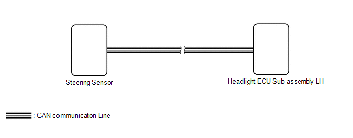
DESCRIPTION
The headlight ECU sub-assembly LH receives steering angle signals from the steering sensor via CAN communication and performs light control.
|
DTC No. | Detection Item |
DTC Detection Condition | Trouble Area |
DTC Output from |
|---|---|---|---|---|
|
B2414 | Steering Position Sensor |
| Electronically controlled brake system |
Headlight ECU sub-assembly LH |
WIRING DIAGRAM
PROCEDURE
| 1. |
CLEAR DTC |
(a) Connect the Techstream to the DLC3.
(b) Turn the engine switch on (IG).
(c) Turn the Techstream on.
(d) Enter the following menus: Body Electrical / HL AutoLeveling / Trouble Codes.
(e) Clear the DTCs.
Body Electrical > HL AutoLeveling > Clear DTCs
|
| 2. |
CHECK FOR DTC |
(a) Connect the Techstream to the DLC3.
(b) Turn the engine switch on (IG).
(c) Wait 10 seconds or more.
(d) Turn the Techstream on.
(e) Enter the following menus: Body Electrical / HL AutoLeveling / Trouble Codes.
(f) Check for DTCs.
Body Electrical > HL AutoLeveling > Trouble CodesOK:
DTC B2414 is not output.
| OK |  | USE SIMULATION METHOD TO CHECK |
| NG | | GO TO ELECTRONICALLY CONTROLLED BRAKE SYSTEM |
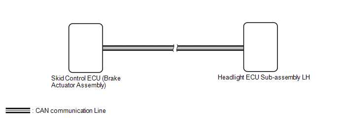
DESCRIPTION
The headlight ECU sub-assembly LH receives speed signals from the skid control ECU (brake actuator assembly) via CAN communication and performs light control.
|
DTC No. | Detection Item |
DTC Detection Condition | Trouble Area |
DTC Output from |
|---|---|---|---|---|
|
B2415 | Vehicle Speed Sensor |
| Electronically controlled brake system |
Headlight ECU sub-assembly LH |
WIRING DIAGRAM
PROCEDURE
| 1. |
CLEAR DTC |
(a) Connect the Techstream to the DLC3.
(b) Turn the engine switch on (IG).
(c) Turn the Techstream on.
(d) Enter the following menus: Body Electrical / HL AutoLeveling / Trouble Codes.
(e) Clear the DTCs.
Body Electrical > HL AutoLeveling > Clear DTCs
|
| 2. |
CHECK FOR DTC |
(a) Connect the Techstream to the DLC3.
(b) Turn the engine switch on (IG).
(c) Wait 10 seconds or more.
(d) Turn the Techstream on.
(e) Enter the following menus: Body Electrical / HL AutoLeveling / Trouble Codes.
(f) Check for DTCs.
Body Electrical > HL AutoLeveling > Trouble CodesOK:
DTC B2415 is not output.
| OK |  | USE SIMULATION METHOD TO CHECK |
| NG | | GO TO ELECTRONICALLY CONTROLLED BRAKE SYSTEM |
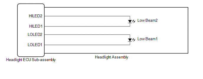
DESCRIPTION
The headlight ECU sub-assembly LH and headlight ECU sub-assembly RH internally boost the power supply voltage to ensure a constant supplied current for the low beam LED of their respective headlight.
By monitoring the LED power supply voltage, abnormal current and malfunctions can be detected.
|
DTC No. | Detection Item |
DTC Detection Condition | Trouble Area |
DTC Output from |
|---|---|---|---|---|
|
B2439 | Headlight LH Circuit |
|
| Headlight ECU sub-assembly LH |
|
B243A | Headlight RH Circuit |
|
| Headlight ECU sub-assembly RH |
WIRING DIAGRAM
CAUTION / NOTICE / HINT
NOTICE:
Click here 
Click here
PROCEDURE
|
1. | CLEAR DTC |
(a) Connect the Techstream to the DLC3.
(b) Turn the engine switch on (IG).
(c) Turn the Techstream on.
(d) Enter the following menus: Body Electrical / HL AutoLeveling or HL AutoLeveling (Sub) / Trouble Codes.
(e) Clear the DTCs.
Body Electrical > HL AutoLeveling > Clear DTCs Body Electrical > HL AutoLeveling (Sub) > Clear DTCs
|
| 2. |
CHECK FOR DTC |
(a) Connect the Techstream to the DLC3.
(b) Turn the engine switch on (IG).
(c) Operate the light control switch to turn on the low beam headlights and wait 10 seconds or more.
(d) Turn the Techstream on.
(e) Enter the following menus: Body Electrical / HL AutoLeveling or HL AutoLeveling (Sub) / Trouble Codes.
(f) Check for DTCs.
Body Electrical > HL AutoLeveling > Trouble Codes Body Electrical > HL AutoLeveling (Sub) > Trouble CodesOK:
DTC B2439 and B243A are not output.
|
Result | Proceed to |
|---|---|
|
OK | A |
|
NG (DTC B2439 is output) |
B |
| NG (DTC B243A is output) |
C |
| A |
 | USE SIMULATION METHOD TO CHECK |
| C |
| GO TO STEP 6 |
|
| 3. |
CHECK HEADLIGHT ASSEMBLY LH |
(a) Remove each headlight ECU sub-assembly, interchange the headlight assembly LH with RH and connect the connectors.
Click here
|
| 4. |
CLEAR DTC |
(a) Connect the Techstream to the DLC3.
(b) Turn the engine switch on (IG).
(c) Turn the Techstream on.
(d) Enter the following menus: Body Electrical / HL AutoLeveling or HL AutoLeveling (Sub) / Trouble Codes.
(e) Clear the DTCs.
Body Electrical > HL AutoLeveling > Clear DTCs Body Electrical > HL AutoLeveling (Sub) > Clear DTCs
|
| 5. |
CHECK FOR DTC |
(a) Connect the Techstream to the DLC3.
(b) Turn the engine switch on (IG).
(c) Operate the light control switch to turn on the low beam headlights and wait 10 seconds or more.
(d) Turn the Techstream on.
(e) Enter the following menus: Body Electrical / HL AutoLeveling or HL AutoLeveling (Sub) / Trouble Codes.
(f) Check for DTCs.
Body Electrical > HL AutoLeveling > Trouble Codes Body Electrical > HL AutoLeveling (Sub) > Trouble Codes|
Result | Proceed to |
|---|---|
|
DTC B2439 is output | A |
|
DTC B243A is output | B |
| A |
| REPLACE HEADLIGHT ECU SUB-ASSEMBLY LH |
| B |
| REPLACE HEADLIGHT ASSEMBLY LH |
| 6. |
CHECK HEADLIGHT ASSEMBLY RH |
(a) Remove each headlight ECU sub-assembly, interchange the headlight assembly RH with LH and connect the connectors.
Click here
|
| 7. |
CLEAR DTC |
(a) Connect the Techstream to the DLC3.
(b) Turn the engine switch on (IG).
(c) Turn the Techstream on.
(d) Enter the following menus: Body Electrical / HL AutoLeveling or HL AutoLeveling (Sub) / Trouble Codes.
(e) Clear the DTCs.
Body Electrical > HL AutoLeveling > Clear DTCs Body Electrical > HL AutoLeveling (Sub) > Clear DTCs
|
| 8. |
CHECK FOR DTC |
(a) Connect the Techstream to the DLC3.
(b) Turn the engine switch on (IG).
(c) Operate the light control switch to turn on the low beam headlights and wait 10 seconds or more.
(d) Turn the Techstream on.
(e) Enter the following menus: Body Electrical / HL AutoLeveling or HL AutoLeveling (Sub) / Trouble Codes.
(f) Check for DTCs.
Body Electrical > HL AutoLeveling > Trouble Codes Body Electrical > HL AutoLeveling (Sub) > Trouble Codes|
Result | Proceed to |
|---|---|
|
DTC B243A is output | A |
|
DTC B2439 is output | B |
| A |
| REPLACE HEADLIGHT ECU SUB-ASSEMBLY RH |
| B |
| REPLACE HEADLIGHT ASSEMBLY RH |
DESCRIPTION
The headlight ECU sub-assembly LH stores this DTC if the vehicle specifications have not been stored.
|
DTC No. | Detection Item |
DTC Detection Condition | Trouble Area |
DTC Output from |
|---|---|---|---|---|
|
B2451 | Variation Code not Written |
| Headlight ECU sub-assembly LH |
Headlight ECU sub-assembly LH |
CAUTION / NOTICE / HINT
NOTICE:
If the headlight ECU sub-assembly LH has been replaced, it is necessary to synchronize the vehicle information the headlight ECU sub-assembly LH.
Click here

PROCEDURE
| 1. |
SYNCHRONIZE VEHICLE INFORMATION |
(a) Synchronize the vehicle information.
Click here
|
| 2. |
CLEAR DTC |
(a) Connect the Techstream to the DLC3.
(b) Turn the engine switch on (IG).
(c) Turn the Techstream on.
(d) Enter the following menus: Body Electrical / HL AutoLeveling / Trouble Codes.
(e) Clear the DTCs.
Body Electrical > HL AutoLeveling > Clear DTCs
|
| 3. |
CHECK FOR DTC |
(a) Connect the Techstream to the DLC3.
(b) Turn the engine switch on (IG).
(c) Turn the Techstream on.
(d) Enter the following menus: Body Electrical / HL AutoLeveling / Trouble Codes.
(e) Check for DTCs.
Body Electrical > HL AutoLeveling > Trouble CodesOK:
DTC B2451 is not output.
HINT:
If the headlight ECU sub-assembly LH stores DTC B2451 even though the vehicle information has been synchronized, the headlight ECU sub-assembly LH may be malfunctioning.
| OK |  | END (VEHICLE SPECIFICATIONS WERE NOT STORED) |
| NG | | REPLACE HEADLIGHT ECU SUB-ASSEMBLY LH |
DESCRIPTION
This DTC is stored if the headlight ECU sub-assembly LH for another destination is installed.
|
DTC No. | Detection Item |
DTC Detection Condition | Trouble Area |
DTC Output from |
|---|---|---|---|---|
|
B2456 | Left Headlight ECU Variation Error |
|
| Headlight ECU sub-assembly LH |
CAUTION / NOTICE / HINT
NOTICE:
Click here 
Click here
Click here
PROCEDURE
|
1. | CLEAR DTC |
(a) Connect the Techstream to the DLC3.
(b) Turn the engine switch on (IG).
(c) Turn the Techstream on.
(d) Enter the following menus: Body Electrical / HL AutoLeveling / Trouble Codes.
(e) Clear the DTCs.
Body Electrical > HL AutoLeveling > Clear DTCs
|
| 2. |
CHECK FOR DTC |
(a) Connect the Techstream to the DLC3.
(b) Turn the engine switch on (IG).
(c) Turn the Techstream on.
(d) Enter the following menus: Body Electrical / HL AutoLeveling / Trouble Codes.
(e) Check for DTCs.
Body Electrical > HL AutoLeveling > Trouble CodesOK:
DTC B2456 is not output.
| OK |  | USE SIMULATION METHOD TO CHECK |
|
| 3. |
CHECK ECM |
(a) Check if the part number of the ECM installed to the vehicle is correct.
OK:
Part number is correct.
| NG | | REPLACE ECM |
|
| 4. |
CHECK MAIN BODY ECU (MULTIPLEX NETWORK BODY ECU) |
(a) Check if the part number of the main body ECU (multiplex network body ECU) installed to the vehicle is correct.
OK:
Part number is correct.
| OK | | REPLACE HEADLIGHT ECU SUB-ASSEMBLY LH |
| NG | | REPLACE MAIN BODY ECU (MULTIPLEX NETWORK BODY ECU) |
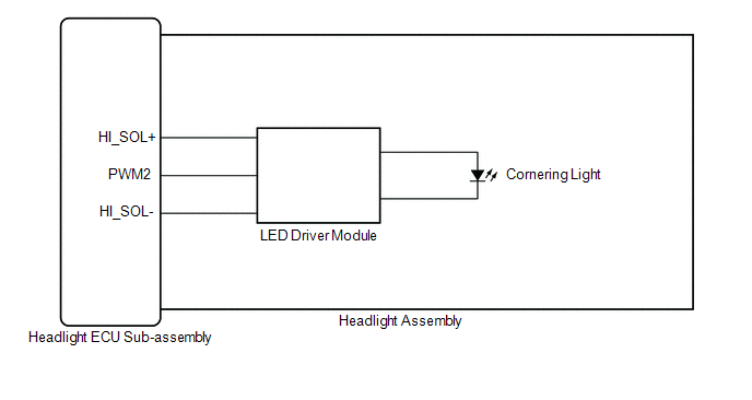
DESCRIPTION
The headlight ECU sub-assembly controls the cornering lights.
WIRING DIAGRAM
CAUTION / NOTICE / HINT
NOTICE:
Click here 
Click here
PROCEDURE
|
1. | CHECK LIGHTS |
(a) Check the illumination of each cornering lights.
|
Result | Proceed to |
|---|---|
|
LH side cornering light does not illuminate |
A |
| RH side cornering light does not illuminate |
B |
| B |
 | GO TO STEP 5 |
|
| 2. |
PERFORM ACTIVE TEST USING TECHSTREAM |
(a) Connect the Techstream to the DLC3.
(b) Turn the engine switch on (IG).
(c) Turn the Techstream on.
(d) Enter the following menus: Body Electrical / HL AutoLeveling / Active Test.
(e) Perform the Active Test according to the display on the Techstream.
Body Electrical > HL AutoLeveling > Active Test|
Tester Display | Measurement Item |
Control Range | Diagnostic Note |
|---|---|---|---|
|
Cornering Light/Front Side Illuminate Light |
Cornering light/front side illuminate light |
OFF or ON | - |
|
Tester Display |
|---|
| Cornering Light/Front Side Illuminate Light |
OK:
Cornering light turn on.
| OK | | PROCEED TO NEXT SUSPECTED AREA SHOWN IN PROBLEM SYMPTOMS TABLE |
|
| 3. |
CHECK HEADLIGHT ASSEMBLY LH |
(a) Remove each headlight ECU sub-assembly, interchange the headlight assembly LH with RH and connect the connectors.
Click here
|
| 4. |
CHECK OPERATION (CORNERING LIGHT) |
(a) Check that the cornering light operates normally.
Click here
OK:
Cornering light operates normally.
| OK | | REPLACE HEADLIGHT ECU SUB-ASSEMBLY LH |
| NG | | REPLACE HEADLIGHT ASSEMBLY LH |
| 5. |
PERFORM ACTIVE TEST USING TECHSTREAM |
(a) Connect the Techstream to the DLC3.
(b) Turn the engine switch on (IG).
(c) Turn the Techstream on.
(d) Enter the following menus: Body Electrical / HL AutoLeveling (Sub) / Active Test.
(e) Perform the Active Test according to the display on the Techstream.
Body Electrical > HL AutoLeveling (Sub) > Active Test|
Tester Display | Measurement Item |
Control Range | Diagnostic Note |
|---|---|---|---|
|
Cornering Light/Front Side Illuminate Light |
Cornering light/front side illuminate light |
OFF or ON | - |
|
Tester Display |
|---|
| Cornering Light/Front Side Illuminate Light |
OK:
Cornering light turn on.
| OK | | PROCEED TO NEXT SUSPECTED AREA SHOWN IN PROBLEM SYMPTOMS TABLE |
|
| 6. |
CHECK HEADLIGHT ASSEMBLY RH |
(a) Remove each headlight ECU sub-assembly, interchange the headlight assembly RH with LH and connect the connectors.
Click here
|
| 7. |
CHECK OPERATION (CORNERING LIGHT) |
(a) Check that the cornering light operates normally.
Click here
OK:
Cornering light operates normally.
| OK | | REPLACE HEADLIGHT ECU SUB-ASSEMBLY RH |
| NG | | REPLACE HEADLIGHT ASSEMBLY RH |
CUSTOMIZE PARAMETERS
CUSTOMIZE LIGHTING SYSTEM (EXT) (for Gasoline Model with Cornering Light)
NOTICE:
HINT:
The following items can be customized.
(a) Customizing with the Techstream
(1) Connect the Techstream to the DLC3.
(2) Turn the engine switch on (IG).
(3) Turn the Techstream on.
(4) Enter the following menus: Customize Setting / Light Control or Warning.
(5) Select the setting by referring to the table below.
Light Control|
Tester Display | Description |
Default | Setting |
ECU |
|---|---|---|---|---|
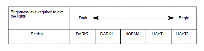
| Disp Ex ON Sen |
Changes the ambient brightness level required to dim the lights such as the indicator lights of the combination meter, A/C indicator light and clock.*A | NORMAL |
000:NORMAL,001:DARK2,010:DARK1,011:LIGHT1,100:LIGHT2 |
Main Body ECU (Multiplex Network Body ECU) |
|
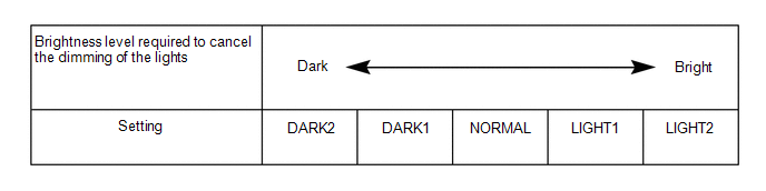
Disp Ex OFF Sen | Changes the ambient brightness level required to cancel the dimming of the lights such as the indicator lights of the combination meter, A/C indicator light and clock.*B | NORMAL |
000:NORMAL,001:DARK2,010:DARK1,011:LIGHT1,100:LIGHT2 |
Main Body ECU (Multiplex Network Body ECU) |
|
Light Auto OFF Delay | Keeps the headlights on for a certain period of time after turning the engine switch off and closing all of doors with the low beam headlights on. |
30 s | 00:OFF,01:30 s,10:60 s,11:90 s |
Main Body ECU (Multiplex Network Body ECU) |
|
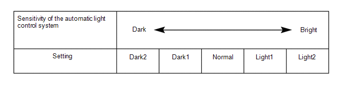
Sensitivity | Adjusts the sensitivity of the automatic light control system.*C |
Normal | 000:Normal,001:Dark2,010:Dark1,011:Light1,100:Light2 |
Main Body ECU (Multiplex Network Body ECU) |
|
DRL Function | Turns the DRL function on/off.* |
ON | 0:OFF,1:ON |
Main Body ECU (Multiplex Network Body ECU) |
|
Light up Clearance Lights at Door Unlock Function |
Turns on the parking lights and the taillights for 15 seconds when a door unlock operation is performed. |
ON | 0:OFF,1:ON |
Main Body ECU (Multiplex Network Body ECU) |
|
Headlight in Conjunction with Wiper |
Turns the low beam headlights on/off according to wiper operation. |
ON | 0:OFF,1:ON |
Main Body ECU (Multiplex Network Body ECU) |
|
Tail Remind Buzzer Function |
Sounds a buzzer when the driver door is opened with the light control switch in the tail or head position. |
ON | 0:OFF,1:ON |
Main Body ECU (Multiplex Network Body ECU) |
HINT:
The sensitivity adjustment may be difficult to confirm. Check by driving the vehicle.
|
Tester Display | Description |
Default | Setting |
ECU |
|---|---|---|---|---|
| Lane Change Flashing Times Adjust |
Function to change the lane change flashing times. |
3 | $00:OFF,$01:3,$02:4,$03:5,$04:6,$05:7 |
Combination Meter Assembly |
(b) Customizing with the multi-display
(1) Turn the engine switch on (IG).
(2) Enter the following menus: MENU / Setup / Vehicle / Vehicle Customization / Lights Settings.
(3) Select the setting by referring to the table below.
|
Display | Default |
Content | Setting |
Relevant ECU |
|---|---|---|---|---|
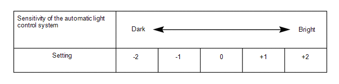
| Headlights Auto-on Sensitivity |
0 | Adjusts the sensitivity of the automatic light control system.*A |
-2, -1, 0, +1 or +2 | Main Body ECU (Multiplex Network Body ECU) |
|
Headlights Auto-off Timer |
30 sec. | Keeps the headlights on for a certain period of time after turning the engine switch off and closing all of doors with the low beam headlights on. |
Off, 30 sec., 60 sec. or 90 sec. | Main Body ECU (Multiplex Network Body ECU) |
|
Daytime Running Lights* |
On | Turns the DRL function on/off. |
On or Off | Main Body ECU (Multiplex Network Body ECU) |
HINT:
The sensitivity adjustment may be difficult to confirm. Check by driving the vehicle.
DATA LIST / ACTIVE TEST
DATA LIST
NOTICE:
In the table below, the values listed under "Normal Condition" are reference values. Do not depend solely on these reference values when deciding whether a part is faulty or not.
HINT:
Using the Techstream to read the Data List allows the values or states of switches, sensors, actuators and other items to be read without removing any parts. This non-intrusive inspection can be very useful because intermittent conditions or signals may be discovered before parts or wiring is disturbed. Reading the Data List information early in troubleshooting is one way to save diagnostic time.
(a) Connect the Techstream to the DLC3.
(b) Turn the engine switch on (IG).
(c) Turn the Techstream on.
(d) Enter the following menus:
(1) for Main Body: Body Electrical / Main Body / Data List.
(2) for HL AutoLeveling: Body Electrical / HL AutoLeveling / Data List.
(3) for HL AutoLeveling (Sub): Body Electrical / HL AutoLeveling (Sub) / Data List.
(4) for Steering Angle Sensor: Chassis / Steering Angle Sensor / Data List.
(5) for Combination Meter: Body Electrical / Combination Meter / Data List.
(6) for Front Recognition Camera: Chassis / Front Recognition Camera / Data List.
(e) Read the Data List according to the display on the Techstream.
Body Electrical > Main Body > Data List|
Tester Display | Measurement Item |
Range | Normal Condition |
Diagnostic Note |
|---|---|---|---|---|
|
Auto High Beam Main Switch |
Auto high beam switch signal |
OFF or ON | OFF: Auto high beam switch not pressed ON: Auto high beam switch pressed |
- |
| Head Light SW (Head) |
Light control switch head position signal |
OFF or ON | OFF: Light control switch not in head position ON: Light control switch in head position |
- |
| Insolation Amount of Solar Sensor RH |
Solar sensor RH condition |
0 to 51100 or SensorFail |
Condition can be displayed |
- |
| Insolation Amount of Solar Sensor LH |
Solar sensor LH condition |
0 to 51100 or SensorFail |
Condition can be displayed |
- |
| Light Sensor Illuminance |
Light control sensor illuminance |
0 to 8191 lx or SensorFail |
Value is output according to ambient light level |
- |
| Light Sensor Connection Status |
Light control sensor connection status |
OFF or ON | OFF: Automatic light control sensor has not been connected ON: Automatic light control sensor connected or has been connected |
- |
| Headlight Lighting Function |
ECU which controls the lighting system |
Main Body or Lighting Sys ECU |
Main Body: Lighting system controlled by main body ECU (multiplex network body ECU) Lighting Sys ECU: Lighting system is controlled by headlight ECU sub-assembly |
- |
| Sensitivity |
Sensitivity of the automatic light control system |
Light2, Light1, Normal, Dark1 or Dark2 |
Customize setting displayed |
- |
| DRL Function |
Setting of the DRL function on/off |
OFF or ON | Customize setting displayed |
for vehicles with customize setting "DRL Function" |
|
Headlight in Conjunction with Wiper |
Wiper-linked low beam headlight control |
OFF or ON | Customize setting displayed |
- |
| Disp Ex ON Sen |
Ambient brightness level required to dim display lights (combination meter, navigation display, etc.) |
Light2, Light1, Normal, Dark1 or Dark2 |
Customize setting displayed |
- |
| Disp Ex OFF Sen |
Ambient brightness level required to cancel dimming display lights (combination meter, navigation display, etc.) |
Light2, Light1, Normal, Dark1 or Dark2 |
Customize setting displayed |
- |
| Light Auto OFF Delay |
Light auto OFF delay |
Off, 30 s, 60 s or 90 s |
Customize setting displayed |
- |
| Auto H Beam STS0 |
Automatic high beam sensor current state |
Undetec, CAM NA, No sens, Hlight, Taillgt, Speed, Daytime, Village, Malfunc, Delay, Aim Lmt, SAE Mod, Undefin or LIN Err |
Condition can be displayed* |
If the value of this item is not as specified, the automatic high beam sensor system may be malfunctioning. |
|
Auto H Beam STS1 | Automatic high beam sensor state past 1 |
Undetec, CAM NA, No sens, Hlight, Taillgt, Speed, Daytime, Village, Malfunc, Delay, Aim Lmt, SAE Mod, Undefin or LIN Err |
Condition can be displayed* |
Although this item is displayed on the Techstream, it is not applicable to this vehicle. |
|
Auto H Beam STS2 | Automatic high beam sensor state past 2 |
Undetec, CAM NA, No sens, Hlight, Taillgt, Speed, Daytime, Village, Malfunc, Delay, Aim Lmt, SAE Mod, Undefin or LIN Err |
Condition can be displayed* |
Although this item is displayed on the Techstream, it is not applicable to this vehicle. |
|
Auto H Beam STS3 | Automatic high beam sensor state past 3 |
Undetec, CAM NA, No sens, Hlight, Taillgt, Speed, Daytime, Village, Malfunc, Delay, Aim Lmt, SAE Mod, Undefin or LIN Err |
Condition can be displayed* |
Although this item is displayed on the Techstream, it is not applicable to this vehicle. |
|
Auto H Beam STS4 | Automatic high beam sensor state past 4 |
Undetec, CAM NA, No sens, Hlight, Taillgt, Speed, Daytime, Village, Malfunc, Delay, Aim Lmt, SAE Mod, Undefin or LIN Err |
Condition can be displayed* |
Although this item is displayed on the Techstream, it is not applicable to this vehicle. |
|
Auto H Beam STS5 | Automatic high beam sensor state past 5 |
Undetec, CAM NA, No sens, Hlight, Taillgt, Speed, Daytime, Village, Malfunc, Delay, Aim Lmt, SAE Mod, Undefin or LIN Err |
Condition can be displayed* |
Although this item is displayed on the Techstream, it is not applicable to this vehicle. |
|
Auto H Beam STS6 | Automatic high beam sensor state past 6 |
Undetec, CAM NA, No sens, Hlight, Taillgt, Speed, Daytime, Village, Malfunc, Delay, Aim Lmt, SAE Mod, Undefin or LIN Err |
Condition can be displayed* |
Although this item is displayed on the Techstream, it is not applicable to this vehicle. |
|
Auto H Beam STS7 | Automatic high beam sensor state past 7 |
Undetec, CAM NA, No sens, Hlight, Taillgt, Speed, Daytime, Village, Malfunc, Delay, Aim Lmt, SAE Mod, Undefin or LIN Err |
Condition can be displayed* |
Although this item is displayed on the Techstream, it is not applicable to this vehicle. |
|
Light up Clearance Lights at Door Unlock Function |
Setting of the welcome light illumination control customize setting |
OFF or ON | Customize setting displayed |
- |
| Tail Remind Buzzer Function |
Setting of the tail remind buzzer function on/off |
OFF or ON | Customize setting displayed |
- |
| The Number of DTC |
Number of trouble codes |
0 to 255 | Number of stored DTCs displayed |
- |
HINT:
*: The details of each value of the Range are as follows:
|
Display Value | Condition |
Control Condition | Diagnostic Note |
|---|---|---|---|
|
Undetec | Automatic high beam sensor being initialized |
Control suspended (low beam headlights illuminated) |
- |
| CAM NA |
Automatic high beam sensor temporarily disabled due to high temperature, unclear image (due to dirt, fog, etc.), etc. |
Control suspended (low beam headlights illuminated) |
- |
| No sens |
No lights detected | High beam headlights illuminated |
Only when vehicle speed within operation speed range |
|
Hlight | Headlights of oncoming vehicle, etc. detected |
Low beam headlights illuminated |
Only when vehicle speed within operation speed range |
|
Taillgt | Taillights preceding vehicle, etc. detected |
Low beam headlights illuminated |
Only when vehicle speed within operation speed range |
|
Speed | No lights detected and vehicle speed below operation speed |
Low beam headlights illuminated |
- |
| Daytime |
Bright light detected | Low beam headlights illuminated |
- |
| Village |
Streetlights, etc. detected |
Low beam headlights illuminated |
Only when vehicle speed within operation speed range |
|
Delay | Changing between low beams and high beams |
Changing between low beams and high beams |
Only when vehicle speed within operation speed range |
|
SAE Mod | Not applicable |
- | - |
|
Malfunc | |||
| Aim Lmt | |||
|
Undefin | |||
| LIN Err |
|
Tester Display | Measurement Item |
Range | Normal Condition |
Diagnostic Note |
|---|---|---|---|---|
|
Headlight Low Beam State |
Low beam headlight state |
OFF or ON | OFF: Low beam headlights off ON: Low beam headlights on |
- |
| Headlight High Beam State |
High beam headlight state |
OFF or ON | OFF: High beam headlights off ON: High beam headlights on |
- |
| +B |
Headlight ECU sub-assembly LH IG power supply voltage value |
0.00 to 19.75 V | 11.00 to 14.00 V |
- |
| Front Right Wheel Speed Value |
Front right wheel speed |
0.00 to 260.00 km/h (162.00 mph) |
Condition can be displayed |
- |
| Front Left Wheel Speed Value |
Front left wheel speed |
0.00 to 260.00 km/h (162.00 mph) |
Condition can be displayed |
- |
| Vehicle Speed |
Vehicle speed | 0.00 to 260.00 km/h (162.00 mph) |
Condition can be displayed |
- |
| Steering Sensor Signal |
Steering sensor signal value |
-384.0 to 382.5 deg | Changes according to the operation of the steering wheel |
Turning left: Increases Turning right: Decreases |
|
Steering Sensor Center Position |
Steering sensor center position |
-3072.0 to 3070.5 deg | 0.0 deg (tires straight ahead) |
- |
| +B Voltage Value |
Headlight ECU sub-assembly LH +B power supply voltage value |
0.00 to 19.75 V | 11.00 to 14.00 V |
- |
| Leveling Motor Target Position |
Headlight leveling motor target position |
0.0 to 102.3 % | 10.0 to 90.0 % |
Although this item is displayed on the Techstream, it is not applicable to this vehicle. |
|
Steering Sensor Initialization Status |
Steering sensor initialization state |
Incomplete or Completed |
Incomplete: Steering sensor zero point calibration incomplete Completed: Steering sensor zero point calibration complete |
- |
| Clearance Light State |
Parking light state | OFF or ON |
OFF: Parking lights off ON: Parking lights on |
- |
| Right Cornering Light/Front Side Illuminate Light State |
Cornering light RH/front side illumination light RH state |
OFF or ON | OFF: Cornering light RH/front side illumination light RH off ON: Cornering light RH/front side illumination light RH on |
- |
| Left Cornering Light/Front Side Illuminate Light State |
Cornering light LH/front side illumination light LH state |
OFF or ON | OFF: Cornering light LH/front side illumination light LH off ON: Cornering light LH/front side illumination light LH on |
- |
| DRL Operating State |
Daytime running light state |
OFF or ON | OFF: Daytime running lights off ON: Daytime running lights on |
- |
| Number Of Trouble Codes |
Number of trouble codes |
0 to 255 | Number of stored DTCs displayed |
- |
|
Tester Display | Measurement Item |
Range | Normal Condition |
Diagnostic Note |
|---|---|---|---|---|
|
Front Window Washer Switch |
Windshield wiper switch assembly (washer switch) condition |
OFF or ON | OFF: Windshield wiper switch assembly (washer switch) off ON: Windshield wiper switch assembly (washer switch) on |
- |
| Headlight Cleaner Switch |
Headlight cleaner switch condition |
OFF or ON | OFF: Headlight cleaner switch off ON: Headlight cleaner switch on |
Although the item is displayed on the Techstream, it is not applicable to the vehicle. |
|
Headlight Low Beam State |
Low beam headlight state |
OFF or ON | OFF: Low beam headlights off ON: Low beam headlights on |
- |
| Headlight High Beam State |
High beam headlight state |
OFF or ON | OFF: High beam headlights off ON: High beam headlights on |
- |
| Clearance Light State |
Parking light state | OFF or ON |
OFF: Parking lights off ON: Parking lights on |
- |
| DRL State(DRL Operating State) |
Daytime running light state |
OFF or ON | OFF: Daytime running lights off ON: Daytime running lights on |
- |
| +B |
Headlight ECU sub-assembly RH IG power supply voltage value |
0.00 to 19.75 V | 11.00 to 14.00 V |
- |
| +B Voltage Value |
Headlight ECU sub-assembly RH +B power supply voltage value |
0.00 to 19.75 V | 11.00 to 14.00 V |
- |
| Number Of Trouble Codes |
Number of trouble codes |
0 to 255 | Number of stored DTCs displayed |
- |
|
Tester Display | Measurement Item |
Range | Normal Condition |
Diagnostic Note |
|---|---|---|---|---|
|
Light OFF Switch | Light control switch DRL OFF position signal |
OFF or ON | OFF: Light control switch not in DRL OFF position ON: Light control switch in DRL OFF position |
w/ DRL OFF Switch |
|
Auto Light Switch | Light control switch AUTO position signal |
OFF or ON | OFF: Light control switch not in AUTO position ON: Light control switch in AUTO position |
- |
| Head Light Switch (Tail) |
Light control switch tail position signal |
OFF or ON | OFF: Light control switch in neither tail nor head position ON: Light control switch in tail or head position |
- |
| Head Light Switch (Head) |
Light control switch head position signal |
OFF or ON | OFF: Light control switch not in head position ON: Light control switch in head position |
- |
| High Beam Main Switch |
Dimmer switch high position signal |
OFF or ON | OFF: Dimmer switch not in high position ON: Dimmer switch in high position |
- |
| Passing Light Switch |
Dimmer switch high flash position (pass) signal |
OFF or ON | OFF: Dimmer switch not in high flash position ON: Dimmer switch in high flash position |
- |
| Auto High Beam Main Switch |
Auto high beam switch signal |
OFF or ON | OFF: Auto high beam switch off ON: Auto high beam switch on |
Although the item is displayed on the Techstream, it is not applicable to the vehicle. |
|
Turn Signal Switch (Right) |
Turn signal switch (right turn position) signal |
OFF or ON | OFF: Turn signal switch not in right turn position ON: Turn signal switch in right turn position |
- |
| Turn Signal Switch (Left) |
Turn signal switch (left turn position) signal |
OFF or ON | OFF: Turn signal switch not in left turn position ON: Turn signal switch in left turn position |
- |
| Cornering Light/Front Side Illuminate Light Switch |
Turn signal switch (full turn) signal |
OFF or ON | OFF: Turn signal switch not in left or right turn position ON: Turn signal switch in left or right full turn position |
- |
| Front Fog Light Switch |
Front fog light switch signal |
OFF or ON | OFF: Front fog light switch off ON: Front fog light switch on |
Although the item is displayed on the Techstream, it is not applicable to the vehicle. |
|
Rear Fog Light/Bad Weather Switch |
Rear fog light switch signal |
OFF or ON | OFF: Rear fog light switch off ON: Rear fog light switch on |
Although the item is displayed on the Techstream, it is not applicable to the vehicle. |
|
Automatic Light Equipped Info |
Automatic light control system specification information |
Unknown, With or Without |
Unknown: Specification not stored With: Automatic light control system equipped Without: Automatic light control system not equipped |
- |
| Bad Weather Mode Equipped Info |
Bad weather specification information |
Unknown, Without or With |
Unknown: Specification not stored Without: Bad weather specification not equipped With: Bad weather specification equipped |
Although the item is displayed on the Techstream, it is not applicable to the vehicle. |
|
The Number of DTCs | Number of trouble codes |
0 to 255 | Number of stored DTCs displayed |
- |
|
Tester Display | Measurement Item |
Range | Normal Condition |
Diagnostic Note |
|---|---|---|---|---|
|
Turn Signal Switch (Left) |
Turn signal switch (left) signal |
OFF or ON | OFF: Turn signal switch not in left turn position ON: Turn signal switch in left turn position |
Although this item is displayed on the Techstream, it is not applicable to this vehicle. |
|
Turn Signal Switch (Right) |
Turn signal switch (right) signal |
OFF or ON | OFF: Turn signal switch not in right turn position ON: Turn signal switch in right turn position |
Although this item is displayed on the Techstream, it is not applicable to this vehicle. |
|
Turn Switch Signal (Full Turn) |
Turn signal switch (full turn) signal |
OFF or ON | OFF: Turn signal switch not in left or right turn position ON: Turn signal switch in left or right turn position |
Although this item is displayed on the Techstream, it is not applicable to this vehicle. |
|
Hazard Flasher Switch | Hazard warning signal switch signal |
OFF or ON | OFF: Hazard warning signal switch off ON: Hazard warning signal switch on |
- |
| Lane Change Flashing Times Adjust |
Condition of the lane change flashing times |
OFF, 3, 4, 5, 6 or 7 | Customize setting displayed |
- |
|
Tester Display | Measurement Item |
Range | Normal Condition |
Diagnostic Note |
|---|---|---|---|---|
|
High Temperature Status1 |
High temperature malfunction status |
OFF or ON | OFF: Forward recognition camera high temperature malfunction does not exist ON: Forward recognition camera high temperature malfunction exists |
- |
ACTIVE TEST
HINT:
Using the Techstream to perform Active Tests allows relays, VSVs, actuators and other items to be operated without removing any parts. This non-intrusive functional inspection can be very useful because intermittent operation may be discovered before parts or wiring is disturbed. Performing Active Tests early in troubleshooting is one way to save diagnostic time. Data List information can be displayed while performing Active Tests.
(a) Connect the Techstream to the DLC3.
(b) Turn the engine switch on (IG).
(c) Turn the Techstream on.
(d) Enter the following menus:
(1) for Main Body: Body Electrical / Main Body / Active Test.
(2) for HL AutoLeveling: Body Electrical / HL AutoLeveling / Active Test.
(3) for HL AutoLeveling (Sub): Body Electrical / HL AutoLeveling (Sub) / Active Test.
(4) for Combination Meter: Body Electrical / Combination Meter / Active Test.
(e) Perform the Active Test according to the display on the Techstream.
Body Electrical > Main Body > Active Test|
Tester Display | Measurement Item |
Control Range | Diagnostic Note |
|---|---|---|---|
|
Daytime Running Light | Daytime running lights |
OFF or ON | - |
|
Taillight Relay | Taillight relay |
OFF or ON | - |
|
Headlight Relay | Low beam headlights |
OFF or ON | - |
|
Head Light Hi | High beam headlights |
OFF or ON | - |
|
Rear Fog Light Relay | Rear fog lights |
OFF or ON | Although this item is displayed on the Techstream, it is not applicable to this vehicle. |
|
Automatic High Beam Switch Light |
Auto high beam switch indicator light |
OFF or ON | - |
|
Tester Display | Measurement Item |
Control Range | Diagnostic Note |
|---|---|---|---|
|
Drive The Leveling Motor |
Headlight leveling motor upward or downward operation |
Stop, Down or Up | Although this item is displayed on the Techstream, it is not applicable to this vehicle. |
|
Headlight Leveling Indicator |
"Headlight System Malfunction Visit Your Dealer" display |
OFF or ON | - |
|
Clearance Light | Parking lights |
OFF or ON | - |
|
Headlight Low Beam | Low beam headlights |
OFF or ON | - |
|
Headlight High Beam | High beam headlights |
OFF or ON | - |
|
Daytime Running Light | Daytime running lights |
OFF or ON | - |
|
Cornering Light/Front Side Illuminate Light |
Cornering light/front side illuminate light |
OFF or ON | - |
|
Tester Display | Measurement Item |
Control Range | Diagnostic Note |
|---|---|---|---|
|
Headlight Cleaner | Operate headlight cleaner motor and pump assembly |
OFF or ON | Although this item is displayed on the Techstream, it is not applicable to this vehicle. |
|
Clearance Light | Parking lights |
OFF or ON | - |
|
Headlight Low Beam | Low beam headlights |
OFF or ON | - |
|
Headlight High Beam | High beam headlights |
OFF or ON | - |
|
Daytime Running Light | Daytime running lights |
OFF or ON | - |
|
Cornering Light/Front Side Illuminate Light |
Cornering light/front side illumination light |
OFF or ON | - |
|
Tester Display | Measurement Item |
Control Range | Diagnostic Note |
|---|---|---|---|
|
Multi Display All (White) |
Multi-information display (White display) |
OFF or ON | - |
DIAGNOSTIC TROUBLE CODE CHART
Lighting System (for Gasoline Model with Cornering Light)|
DTC No. | Detection Item |
DTC Output from | Link |
|---|---|---|---|
|
B1244 | Light Sensor Circuit |
Main body ECU (multiplex network body ECU) |
|
|
B124B | Automatic High Beam System |
Main body ECU (multiplex network body ECU) |
|
|
B124C | Automatic High Beam Camera |
Main body ECU (multiplex network body ECU) |
|
|
B2414 | Steering Position Sensor |
Headlight ECU sub-assembly LH |
|
|
B2415 | Vehicle Speed Sensor |
Headlight ECU sub-assembly LH |
|
|
B242C | Right Headlight ECU Malfunction |
Headlight ECU sub-assembly RH |
|
|
B242D | Left Headlight ECU Malfunction |
Headlight ECU sub-assembly LH |
|
|
B242E | Open in IG Circuit |
Headlight ECU sub-assembly LH |
|
|
B242E | Open in IG Circuit |
Headlight ECU sub-assembly RH |
|
|
B242F | Open in B Power Line |
Headlight ECU sub-assembly LH |
|
|
B242F | Open in B Power Line |
Headlight ECU sub-assembly RH |
|
|
B2439 | Headlight LH Circuit |
Headlight ECU sub-assembly LH |
|
|
B243A | Headlight RH Circuit |
Headlight ECU sub-assembly RH |
|
|
B243D | Left Low Beam Fan Malfunction |
Headlight ECU sub-assembly LH |
|
|
B243E | Right Low Beam Fan Malfunction |
Headlight ECU sub-assembly RH |
|
|
B2451 | Variation Code not Written |
Headlight ECU sub-assembly LH |
|
|
B2456 | Left Headlight ECU Variation Error |
Headlight ECU sub-assembly LH |
|
|
U0073 | Control Module Communication Bus Off |
Headlight ECU sub-assembly LH |
|
|
U0073 | Control Module Communication Bus OFF |
Headlight ECU sub-assembly RH |
|
|
U0100 | Lost Communication with ECM / PCM "A" |
Headlight ECU sub-assembly LH |
|
|
U0100 | Lost Communication With ECM/PCM "A" |
Main body ECU (multiplex network body ECU) |
|
|
U0101 | Lost Communication with TCM |
Headlight ECU sub-assembly LH |
|
|
U0101 | Lost Communication with TCM |
Main body ECU (multiplex network body ECU) |
|
|
U0120 | Lost Communication With Starter / Generator Control Module |
Main body ECU (multiplex network body ECU) |
|
|
U0126 | Lost Communication with Steering Angle Sensor Module |
Headlight ECU sub-assembly LH |
|
|
U0126 | Lost Communication with Steering Angle Sensor Module |
Headlight ECU sub-assembly RH |
|
|
U0126 | Lost Communication with Steering Angle Sensor Module |
Main body ECU (multiplex network body ECU) |
|
|
U0129 | Lost Communication with Brake System Control Module |
Headlight ECU sub-assembly LH |
|
|
U0129 | Lost Communication with Brake System Control Module |
Main body ECU (multiplex network body ECU) |
|
|
U0142 | Lost Communication with Body Control Module "B" |
Headlight ECU sub-assembly LH |
|
|
U0142 | Lost Communication with Body Control Module "B" |
Headlight ECU sub-assembly RH |
|
|
U0151 | Lost Communication with Restraints Control Module |
Main body ECU (multiplex network body ECU) |
|
|
U0155 | Lost Communication with Instrument Panel Cluster (IPC) Control Module |
Headlight ECU sub-assembly LH |
|
|
U0155 | Lost Communication with Instrument Panel Cluster (IPC) Control Module |
Headlight ECU sub-assembly RH |
|
|
U0155 | Lost Communication with Instrument Panel Cluster (IPC) Control Module |
Main body ECU (multiplex network body ECU) |
|
|
U0163 | Lost Communication with Navigation Control Module |
Main body ECU (multiplex network body ECU) |
|
|
U0164 | Lost Communication with HVAC Control Module |
Main body ECU (multiplex network body ECU) |
|
|
U0182 | Lost Communication With Lighting Control Module Front |
Headlight ECU sub-assembly RH |
|
|
U0182 | Lost Communication with AFS |
Main body ECU (multiplex network body ECU) |
|
|
U0199 | Lost Communication with "Door Control Module A" |
Main body ECU (multiplex network body ECU) |
|
|
U0200 | Lost Communication with "Door Control Module B" |
Main body ECU (multiplex network body ECU) |
|
|
U0208 | Lost Communication with "Seat Control Module A" |
Main body ECU (multiplex network body ECU) |
|
|
U023A | Lost Communication With Image Processing Module "A" |
Main body ECU (multiplex network body ECU) |
|
|
U0242 | Lost Communication With Headlamp Control Module "B" |
Headlight ECU sub-assembly LH |
|
|
U0327 | Software Incompatibility with Vehicle Security Control Module |
Main body ECU (multiplex network body ECU) |
|
|
U1000 | CAN Communication Failure (Message Registry) |
Headlight ECU sub-assembly LH |
|
|
U1000 | CAN Communication Failure (Message Registry) |
Headlight ECU sub-assembly RH |
|
|
U1106 | Lost Communication with Electric Parking Brake Module |
Main body ECU (multiplex network body ECU) |
|
|
U1115 | Lost Communication with Tilt & Telescopic Module |
Main body ECU (multiplex network body ECU) |
|
|
U1117 | Lost Communication with Accessory Gateway |
Main body ECU (multiplex network body ECU) |
|
DTC CHECK / CLEAR
CHECK FOR DTC (MAIN BODY)
(a) Connect the Techstream to the DLC3.
(b) Turn the engine switch on (IG).
(c) Turn the Techstream on.
(d) Enter the following menus: Body Electrical / Main Body / Trouble Codes.
Body Electrical > Main Body > Trouble Codes(e) Check for DTCs.
CHECK FOR DTC (HL AUTOLEVELING)
(a) Connect the Techstream to the DLC3.
(b) Turn the engine switch on (IG).
(c) Turn the Techstream on.
(d) Enter the following menus: Body Electrical / HL AutoLeveling / Trouble Codes.
Body Electrical > HL AutoLeveling > Trouble Codes(e) Check for DTCs.
CHECK FOR DTC (HL AUTOLEVELING (SUB))
(a) Connect the Techstream to the DLC3.
(b) Turn the engine switch on (IG).
(c) Turn the Techstream on.
(d) Enter the following menus: Body Electrical / HL AutoLeveling (Sub) / Trouble Codes.
Body Electrical > HL AutoLeveling (Sub) > Trouble Codes(e) Check for DTCs.
CLEAR DTC (MAIN BODY)
(a) Connect the Techstream to the DLC3.
(b) Turn the engine switch on (IG).
(c) Turn the Techstream on.
(d) Enter the following menus: Body Electrical / Main Body / Trouble Codes.
Body Electrical > Main Body > Clear DTCs(e) Clear the DTCs.
CLEAR DTC (HL AUTOLEVELING)
(a) Connect the Techstream to the DLC3.
(b) Turn the engine switch on (IG).
(c) Turn the Techstream on.
(d) Enter the following menus: Body Electrical / HL AutoLeveling / Trouble Codes.
Body Electrical > HL AutoLeveling > Clear DTCs(e) Clear the DTCs.
CLEAR DTC (HL AUTOLEVELING (SUB))
(a) Connect the Techstream to the DLC3.
(b) Turn the engine switch on (IG).
(c) Turn the Techstream on.
(d) Enter the following menus: Body Electrical / HL AutoLeveling (Sub) / Trouble Codes.
Body Electrical > HL AutoLeveling (Sub) > Clear DTCs(e) Clear the DTCs.
FREEZE FRAME DATA
FREEZE FRAME DATA
(a) Whenever a lighting system (for Gasoline Model with Cornering Light) DTC is stored, the headlight ECU sub-assembly stores the current vehicle state as freeze frame data.
CHECK FREEZE FRAME DATA
(a) Connect the Techstream to the DLC3.
(b) Turn the engine switch on (IG).
(c) Turn the Techstream on.
(d) Enter the following menus:
(1) Body Electrical / HL AutoLeveling / Trouble Codes.
Body Electrical > HL AutoLeveling > Trouble Codes(2) Body Electrical / HL AutoLeveling (Sub) / Trouble Codes.
Body Electrical > HL AutoLeveling (Sub) > Trouble Codes(e) Select a DTC to display its freeze frame data.
Body Electrical > HL AutoLeveling|
Tester Display | Measurement Item |
Range | Normal Condition |
Diagnostic Note |
|---|---|---|---|---|
|
+B | Headlight ECU sub-assembly LH IG power supply voltage value |
0.00 to 19.75 V | 11.00 to 14.00 V |
- |
| +B Voltage Value |
Headlight ECU sub-assembly LH +B power supply voltage value |
0.00 to 19.75 V | 11.00 to 14.00 V |
- |
| Headlight Low Beam State |
Low beam headlight state |
OFF or ON | OFF: Low beam headlights off ON: Low beam headlights on |
- |
| Headlight High Beam State |
High beam headlight state |
OFF or ON | OFF: High beam headlights off ON: High beam headlights on |
- |
| Steering Sensor Signal |
Steering sensor signal value |
-384.0 to 382.5 deg | Changes according to the operation of the steering wheel |
Turning left: Increases Turning right: Decreases |
|
Front Right Wheel Speed Value |
Front right wheel speed |
0.00 to 260.00 km/h (162.00 mph) |
Condition can be displayed |
- |
| Front Left Wheel Speed Value |
Front left wheel speed |
0.00 to 260.00 km/h (162.00 mph) |
Condition can be displayed |
- |
| Vehicle Acceleration |
Vehicle acceleration |
-445.64 to 445.63 m/s2 |
Condition can be displayed |
- |
| Clearance Light State |
Parking light state | OFF or ON |
OFF: Parking lights off ON: Parking lights on |
- |
| Right Cornering Light/Front Side Illuminate Light State |
Cornering light RH/front side illumination light RH state |
OFF or ON | OFF: Cornering light RH/front side illumination light RH off ON: Cornering light RH/front side illumination light RH on |
- |
| Left Cornering Light/Front Side Illuminate Light State |
Cornering light LH/front side illumination light LH state |
OFF or ON | OFF: Cornering light LH/front side illumination light LH off ON: Cornering light LH/front side illumination light LH on |
- |
| DRL Operating State |
Daytime running light state |
OFF or ON | OFF: Daytime running lights off ON: Daytime running lights on |
- |
| Number Of Trouble Codes |
Number of trouble codes |
0 to 255 | Number of stored DTCs displayed |
- |
|
Tester Display | Measurement Item |
Range | Normal Condition |
Diagnostic Note |
|---|---|---|---|---|
|
+B | Headlight ECU sub-assembly RH IG power supply voltage value |
0.00 to 19.75 V | 11.00 to 14.00 V |
- |
| +B Voltage Value |
Headlight ECU sub-assembly RH +B power supply voltage value |
0.00 to 19.75 V | 11.00 to 14.00 V |
- |
| Headlight Low Beam State |
Low beam headlight state |
OFF or ON | OFF: Low beam headlights off ON: Low beam headlights on |
- |
| Headlight High Beam State |
High beam headlight state |
OFF or ON | OFF: High beam headlights off ON: High beam headlights on |
- |
| Clearance Light State |
Parking light state | OFF or ON |
OFF: Parking lights off ON: Parking lights on |
- |
| DRL State(DRL Operating State) |
Daytime running light state |
OFF or ON | OFF: Daytime running lights off ON: Daytime running lights on |
- |
| Number Of Trouble Codes |
Number of trouble codes |
0 to 255 | Number of stored DTCs displayed |
- |
CLEAR FREEZE FRAME DATA
NOTICE:
Clearing the DTCs will also clear the freeze frame data.
(a) Connect the Techstream to the DLC3.
(b) Turn the engine switch on (IG).
(c) Clear the DTCs and freeze frame data.
(d) Enter the following menus:
(1) Body Electrical / HL AutoLeveling / Clear DTCs.
Body Electrical > HL AutoLeveling > Clear DTCs(2) Body Electrical / HL AutoLeveling (Sub) / Clear DTCs.
Body Electrical > HL AutoLeveling (Sub) > Clear DTCsDESCRIPTION
When the light control switch is in the tail or head position, the main body ECU (multiplex network body ECU) sends an illumination request signal to the headlight ECU sub-assembly LH/RH to illuminate the front side marker lights.
WIRING DIAGRAM
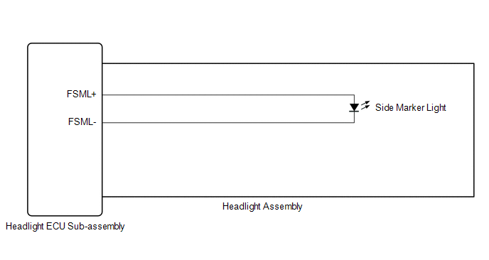
CAUTION / NOTICE / HINT
NOTICE:
Click here 
Click here
PROCEDURE
|
1. | CHECK LIGHTS |
(a) Check the illumination of each front side marker lights.
|
Result | Proceed to |
|---|---|
|
LH side front side marker light does not illuminate |
A |
| RH side front side marker light does not illuminate |
B |
| B |
 | GO TO STEP 5 |
|
| 2. |
PERFORM ACTIVE TEST USING TECHSTREAM |
(a) Connect the Techstream to the DLC3.
(b) Turn the engine switch on (IG).
(c) Turn the Techstream on.
(d) Enter the following menus: Body Electrical / HL AutoLeveling / Active Test.
(e) Perform the Active Test according to the display on the Techstream.
Body Electrical > HL AutoLeveling > Active Test|
Tester Display | Measurement Item |
Control Range | Diagnostic Note |
|---|---|---|---|
|
Clearance Light | Parking lights |
OFF or ON | - |
|
Tester Display |
|---|
| Clearance Light |
OK:
Front side marker light illuminate.
| OK | | PROCEED TO NEXT SUSPECTED AREA SHOWN IN PROBLEM SYMPTOMS TABLE |
|
| 3. |
CHECK HEADLIGHT ASSEMBLY LH |
(a) Remove each headlight ECU sub-assembly, interchange the headlight assembly LH with RH and connect the connectors.
Click here
|
| 4. |
CHECK OPERATION (FRONT SIDE MARKER LIGHT) |
(a) Check that the front side marker light operates normally.
OK:
Front side marker light operates normally.
| OK | | REPLACE HEADLIGHT ECU SUB-ASSEMBLY LH |
| NG | | REPLACE HEADLIGHT ASSEMBLY LH |
| 5. |
PERFORM ACTIVE TEST USING TECHSTREAM |
(a) Connect the Techstream to the DLC3.
(b) Turn the engine switch on (IG).
(c) Turn the Techstream on.
(d) Enter the following menus: Body Electrical / HL AutoLeveling (Sub) / Active Test.
(e) Perform the Active Test according to the display on the Techstream.
Body Electrical > HL AutoLeveling (Sub) > Active Test|
Tester Display | Measurement Item |
Control Range | Diagnostic Note |
|---|---|---|---|
|
Clearance Light | Parking lights |
OFF or ON | - |
|
Tester Display |
|---|
| Clearance Light |
OK:
Front side marker light illuminate.
| OK | | PROCEED TO NEXT SUSPECTED AREA SHOWN IN PROBLEM SYMPTOMS TABLE |
|
| 6. |
CHECK HEADLIGHT ASSEMBLY RH |
(a) Remove each headlight ECU sub-assembly, interchange the headlight assembly RH with LH and connect the connectors.
Click here
|
| 7. |
CHECK OPERATION (FRONT SIDE MARKER LIGHT) |
(a) Check that the front side marker light operates normally.
OK:
Front side marker light operates normally.
| OK | | REPLACE HEADLIGHT ECU SUB-ASSEMBLY RH |
| NG | | REPLACE HEADLIGHT ASSEMBLY RH |
DESCRIPTION
The combination meter assembly receives the hazard warning signal switch (radio and display receiver assembly) on signal and controls the operation of the hazard warning lights.
WIRING DIAGRAM
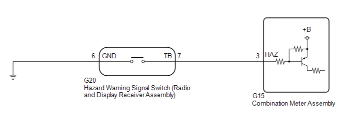
CAUTION / NOTICE / HINT
NOTICE:
When replacing the combination meter assembly, always replace it with a new one. If a combination meter assembly which was installed to another vehicle is used, the information stored in it will not match the information from the vehicle and a DTC may be stored.
PROCEDURE
| 1. |
READ VALUE USING TECHSTREAM |
(a) Connect the Techstream to the DLC3.
(b) Turn the engine switch on (IG).
(c) Turn the Techstream on.
(d) Enter the following menus: Body Electrical / Combination Meter / Data List.
(e) Read the Data List according to the display on the Techstream.
Body Electrical > Combination Meter > Data List|
Tester Display | Measurement Item |
Range | Normal Condition |
Diagnostic Note |
|---|---|---|---|---|
|
Hazard Flasher Switch | Hazard warning signal switch signal |
OFF or ON | OFF: Hazard warning signal switch off ON: Hazard warning signal switch on |
- |
|
Tester Display |
|---|
| Hazard Flasher Switch |
OK:
Normal conditions listed above are displayed.
| OK |  | PROCEED TO NEXT SUSPECTED AREA SHOWN IN PROBLEM SYMPTOMS TABLE |
|
| 2. |
INSPECT HAZARD WARNING SIGNAL SWITCH (RADIO AND DISPLAY RECEIVER ASSEMBLY) |
(a) Remove the hazard warning signal switch (radio and display receiver assembly).
Click here 
(b) Inspect the hazard warning signal switch (radio and display receiver assembly).
Click here
| NG | | REPLACE HAZARD WARNING SIGNAL SWITCH (RADIO AND DISPLAY RECEIVER ASSEMBLY) |
|
| 3. |
CHECK HARNESS AND CONNECTOR (HAZARD WARNING SIGNAL SWITCH (RADIO AND DISPLAY RECEIVER ASSEMBLY) - COMBINATION METER ASSEMBLY AND BODY GROUND) |
(a) Disconnect the G15 combination meter assembly connector.
(b) Measure the resistance according to the value(s) in the table below.
Standard Resistance:
|
Tester Connection | Condition |
Specified Condition |
|---|---|---|
|
G20-7 (TB) - G15-3 (HAZ) |
Always | Below 1 Ω |
|
G20-7 (TB) or G15-3 (HAZ) - Body ground |
Always | 10 kΩ or higher |
|
G20-6 (GND) - Body ground |
Always | Below 1 Ω |
| OK | | REPLACE COMBINATION METER ASSEMBLY |
| NG | | REPAIR OR REPLACE HARNESS OR CONNECTOR |
DESCRIPTION
The steering sensor receives the following switch information:
WIRING DIAGRAM
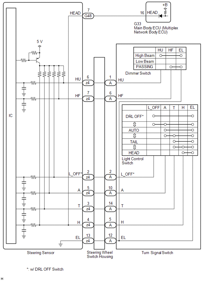
CAUTION / NOTICE / HINT
NOTICE:
Before replacing the main body ECU (multiplex network body ECU), refer to Registration.
Click here 
PROCEDURE
| 1. |
READ VALUE USING TECHSTREAM |
(a) Connect the Techstream to the DLC3.
(b) Turn the engine switch on (IG).
(c) Turn the Techstream on.
(d) Enter the following menus: Chassis / Steering Angle Sensor / Data List.
(e) Read the Data List according to the display on the Techstream.
Chassis > Steering Angle Sensor > Data List|
Tester Display | Measurement Item |
Range | Normal Condition |
Diagnostic Note |
|---|---|---|---|---|
|
Light OFF Switch | Light control switch DRL OFF position signal |
OFF or ON | OFF: Light control switch not in DRL OFF position ON: Light control switch in DRL OFF position |
w/ DRL OFF Switch |
|
Auto Light Switch | Light control switch AUTO position signal |
OFF or ON | OFF: Light control switch not in AUTO position ON: Light control switch in AUTO position |
- |
| Head Light Switch (Tail) |
Light control switch tail position signal |
OFF or ON | OFF: Light control switch in neither tail nor head position ON: Light control switch in tail or head position |
- |
| Head Light Switch (Head) |
Light control switch head position signal |
OFF or ON | OFF: Light control switch not in head position ON: Light control switch in head position |
- |
| High Beam Main Switch |
Dimmer switch high position signal |
OFF or ON | OFF: Dimmer switch not in high position ON: Dimmer switch in high position |
- |
| Passing Light Switch |
Dimmer switch high flash position (pass) signal |
OFF or ON | OFF: Dimmer switch not in high flash position ON: Dimmer switch in high flash position |
- |
|
Tester Display |
|---|
| Light OFF Switch |
|
Auto Light Switch |
|
Head Light Switch (Tail) |
|
Head Light Switch (Head) |
|
High Beam Main Switch |
|
Passing Light Switch |
OK:
Normal conditions listed above are displayed.
| NG |  | GO TO STEP 5 |
|
| 2. |
READ VALUE USING TECHSTREAM |
(a) Connect the Techstream to the DLC3.
(b) Turn the engine switch on (IG).
(c) Turn the Techstream on.
(d) Enter the following menus: Body Electrical / Main Body / Data List.
(e) Read the Data List according to the display on the Techstream.
Body Electrical > Main Body > Data List|
Tester Display | Measurement Item |
Range | Normal Condition |
Diagnostic Note |
|---|---|---|---|---|
|
Head Light SW (Head) | Light control switch head position signal |
OFF or ON | OFF: Light control switch not in head position ON: Light control switch in head position |
- |
|
Tester Display |
|---|
| Head Light SW (Head) |
OK:
Normal conditions listed above are displayed.
| OK | | PROCEED TO NEXT SUSPECTED AREA SHOWN IN PROBLEM SYMPTOMS TABLE |
|
| 3. |
INSPECT STEERING SENSOR |

|
*a | Component without harness connected (Steering Sensor) | - |
- |
(a) Remove the steering sensor.
Click here
(b) Measure the resistance according to the value(s) in the table below.
Standard Resistance:
|
Tester Connection | Condition |
Specified Condition |
|---|---|---|
|
G48-7 (HEAD) - z4-4 (H) |
Always | Below 1 Ω |
| NG | | REPLACE STEERING SENSOR |
|
| 4. |
CHECK HARNESS AND CONNECTOR (STEERING SENSOR - MAIN BODY ECU (MULTIPLEX NETWORK BODY ECU)) |
(a) Disconnect the G33 main body ECU (multiplex network body ECU) connector.
(b) Measure the resistance according to the value(s) in the table below.
Standard Resistance:
|
Tester Connection | Condition |
Specified Condition |
|---|---|---|
|
G48-7 (HEAD) - G33-16 (HEAD) |
Always | Below 1 Ω |
|
G48-7 (HEAD) or G33-16 (HEAD) - Body ground |
Always | 10 kΩ or higher |
| OK | | REPLACE MAIN BODY ECU (MULTIPLEX NETWORK BODY ECU) |
| NG | | REPAIR OR REPLACE HARNESS OR CONNECTOR |
| 5. |
INSPECT TURN SIGNAL SWITCH |
(a) Remove the turn signal switch.
Click here
(b) Inspect the turn signal switch.
Click here
| NG | | REPLACE TURN SIGNAL SWITCH |
|
| 6. |
INSPECT STEERING WHEEL SWITCH HOUSING |
(a) Remove the steering wheel switch housing.
Click here
(b) Inspect the steering wheel switch housing.
Click here
| OK | | REPLACE STEERING SENSOR |
| NG | | REPLACE STEERING WHEEL SWITCH HOUSING |
DESCRIPTION
The headlight ECU sub-assembly controls the high beam headlights.
WIRING DIAGRAM
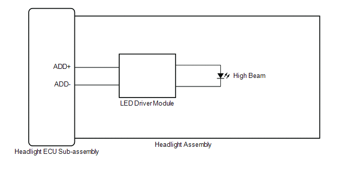
CAUTION / NOTICE / HINT
NOTICE:
Click here 
Click here
PROCEDURE
|
1. | CHECK LIGHTS |
(a) Check the illumination of each high beam lights.
|
Result | Proceed to |
|---|---|
|
LH side high beam light does not illuminate |
A |
| RH side high beam light does not illuminate |
B |
| B |
 | GO TO STEP 5 |
|
| 2. |
PERFORM ACTIVE TEST USING TECHSTREAM |
(a) Connect the Techstream to the DLC3.
(b) Turn the engine switch on (IG).
(c) Turn the Techstream on.
(d) Enter the following menus: Body Electrical / HL AutoLeveling / Active Test.
(e) Perform the Active Test according to the display on the Techstream.
Body Electrical > HL AutoLeveling > Active Test|
Tester Display | Measurement Item |
Control Range | Diagnostic Note |
|---|---|---|---|
|
Headlight High Beam | High beam headlights |
OFF or ON | - |
|
Tester Display |
|---|
| Headlight High Beam |
OK:
High beam headlight turn on.
| OK | | PROCEED TO NEXT SUSPECTED AREA SHOWN IN PROBLEM SYMPTOMS TABLE |
|
| 3. |
CHECK HEADLIGHT ASSEMBLY LH |
(a) Remove each headlight ECU sub-assembly, interchange the headlight assembly LH with RH and connect the connectors.
Click here
|
| 4. |
CHECK OPERATION (HIGH BEAM HEADLIGHT) |
(a) Check that the high beam headlight operates normally.
OK:
High beam headlight operates normally.
| OK | | REPLACE HEADLIGHT ECU SUB-ASSEMBLY LH |
| NG | | REPLACE HEADLIGHT ASSEMBLY LH |
| 5. |
PERFORM ACTIVE TEST USING TECHSTREAM |
(a) Connect the Techstream to the DLC3.
(b) Turn the engine switch on (IG).
(c) Turn the Techstream on.
(d) Enter the following menus: Body Electrical / HL AutoLeveling (Sub) / Active Test.
(e) Perform the Active Test according to the display on the Techstream.
Body Electrical > HL AutoLeveling (Sub) > Active Test|
Tester Display | Measurement Item |
Control Range | Diagnostic Note |
|---|---|---|---|
|
Headlight High Beam | High beam headlights |
OFF or ON | - |
|
Tester Display |
|---|
| Headlight High Beam |
OK:
High beam headlight turn on.
| OK | | PROCEED TO NEXT SUSPECTED AREA SHOWN IN PROBLEM SYMPTOMS TABLE |
|
| 6. |
CHECK HEADLIGHT ASSEMBLY RH |
(a) Remove each headlight ECU sub-assembly, interchange the headlight assembly RH with LH and connect the connectors.
Click here
|
| 7. |
CHECK OPERATION (HIGH BEAM HEADLIGHT) |
(a) Check that the high beam headlight operates normally.
OK:
High beam headlight operates normally.
| OK | | REPLACE HEADLIGHT ECU SUB-ASSEMBLY RH |
| NG | | REPLACE HEADLIGHT ASSEMBLY RH |
CAUTION / NOTICE / HINT
HINT:
PROCEDURE
|
1. | VEHICLE BROUGHT TO WORKSHOP |
|
| 2. |
CUSTOMER PROBLEM ANALYSIS |
HINT:
|
What |
Vehicle model, system name |
|
When |
Date, time, occurrence frequency |
|
Where |
Road conditions |
|
Under what conditions? |
Driving conditions, weather conditions |
|
How did it happen? |
Problem symptoms |
|
| 3. |
PRE-CHECK |
(a) Measure the battery voltage.
Standard Voltage:
11 to 14 V
If the voltage is below 11 V, recharge or replace the battery before proceeding to the next step.
(b) Check the fuses and relays.
(c) Check the connector connections and terminals to make sure that there are no abnormalities such as loose connections, deformation, etc.
|
| 4. |
CHECK COMMUNICATION FUNCTION OF CAN COMMUNICATION SYSTEM* |
(a) Using the Techstream, check for CAN communication system DTCs.
Click here

|
Result | Proceed to |
|---|---|
|
CAN DTCs are not output |
A |
| CAN DTCs are output |
B |
| B |
 | GO TO CAN COMMUNICATION SYSTEM |
|
| 5. |
CHECK FOR DTC* |
(a) Check for DTCs.
Body Electrical > Main Body > Trouble Codes Body Electrical > HL AutoLeveling > Trouble Codes Body Electrical > HL AutoLeveling (Sub) > Trouble Codes|
Result | Proceed to |
|---|---|
|
DTCs are not output | A |
|
DTCs are output | B |
| B |
| GO TO DIAGNOSTIC TROUBLE CODE CHART |
|
| 6. |
PROBLEM SYMPTOMS TABLE |
(a) Refer to Problem Symptoms Table.
Click here
|
Result | Proceed to |
|---|---|
|
Fault is not listed in Problem Symptoms Table |
A |
| Fault is listed in Problem Symptoms Table |
B |
| B |
| GO TO PROBLEM SYMPTOMS TABLE |
|
| 7. |
OVERALL ANALYSIS AND TROUBLESHOOTING* |
(a) Operation Check.
Click here
(b) Terminals of ECU.
Click here
(c) Data List / Active Test.
Click here
(d) On-vehicle Inspection.
(e) Inspection.
|
| 8. |
ADJUST, REPAIR OR REPLACE |
|
| 9. |
CONFIRMATION TEST |
| NEXT | | END |
INITIALIZATION
NOTICE:
|
Replaced Part or Performed Procedure |
Necessary Procedures |
Proceed to |
|---|---|---|
|
Headlight ECU sub-assembly LH or headlight assembly LH |
Synchronize the vehicle information |
SYNCHRONIZE VEHICLE INFORMATION |
|
Battery terminal is disconnected and connected. |
Steering sensor zero point calibration |
|
Click here 
SYNCHRONIZE VEHICLE INFORMATION (When using the TECHSTREAM)
NOTICE:
If synchronization fails, make sure to turn the engine switch off then back on (IG) before performing synchronization again.
(a) Turn the engine switch off.
(b) Connect the Techstream to the DLC3.
(c) Turn the engine switch on (IG).
(d) Check that the "Headlight Auto Leveling System Unavailable Visit Your Dealer" warning message is displayed on the multi-information display.
(e) Enter the following menus: Body Electrical / HL AutoLeveling / Utility / ECU Information Sync.
Body Electrical > HL AutoLeveling > Utility|
Tester Display |
|---|
| ECU Information Sync |
(f) Check the display on the Techstream and press "Next".
(g) Check that the "Headlight System Malfunction Visit Your Dealer" warning message continuously blinks 6 times at 2 Hz on the multi-information display.
HINT:
If the "Headlight System Malfunction Visit Your Dealer" warning message does not start blinking on the multi-information display after perform the procedure again.
(h) Press "Exit".
(i) Turn the engine switch off.
NOTICE:
If synchronization fails, make sure to turn the engine switch off then back on (IG) before performing synchronization again.
SYNCHRONIZE VEHICLE INFORMATION (When not using the TECHSTREAM)
(a) Turn the engine switch on (IG).
(b) Check that the "Headlight Auto Leveling System Unavailable Visit Your Dealer" warning message is displayed on the multi-information display.
(c) Using the headlight dimmer switch, turn the low beam headlights on and off 8 times within 20 seconds after turning the engine switch on (IG).
NOTICE:
If the low beam headlights illuminate when the engine switch is on (IG), shine a light on the automatic light control sensor to turn the low beam headlights off before operating the headlight dimmer switch.
HINT:
If this step cannot be completed within 20 seconds, turn the engine switch off. Then, turn the engine switch on (IG) and restart the procedure.
(d) Check that the "Headlight System Malfunction Visit Your Dealer" warning message continuously blinks 6 times at 2 Hz on the multi-information display.
HINT:
If the "Headlight System Malfunction Visit Your Dealer" warning message does not start blinking on the multi-information display after perform the procedure again.
(e) Turn the engine switch off.
OPERATION CHECK
AUTOMATIC LIGHT CONTROL SYSTEM OPERATION CHECK
NOTICE:
Make sure that the customize settings are set to default when performing the automatic light control system operation check.
Click here 
(a) Turn the engine switch on (IG).
(b) Turn the light control switch to the AUTO position.
(c) Cover the automatic light control sensor.
(d) Check that the taillights and low beam headlights come on.
(e) Uncover the automatic light control sensor.
(f) Check that the low beam headlights and taillights turn off.
LIGHT AUTO TURN-OFF SYSTEM OPERATION CHECK
NOTICE:
Make sure that the customize settings are set to default when performing the light auto turn-off system operation check.
Click here
(a) When the taillights are on (low beam headlights are not on)
(1) Close all of the doors.
(2) Turn the engine switch on (IG).
(3) Turn the taillights on.
(4) Turn the engine switch off.
(5) Open the driver door.
(6) Check that all of the lights turn off immediately.
(b) When the low beam headlights are on
(1) Close all of the doors.
(2) Turn the engine switch on (IG).
(3) Turn the low beam headlights on.
(4) Turn the engine switch off.
(5) Open any of the doors.
(6) Close the door.
(7) Check that all of the lights turn off after 30 seconds (delay function).
HINT:
Before the lights turn off, if the lock button on the key is pushed after all of the doors are locked, all of the lights will turn off immediately.
DAYTIME RUNNING LIGHT SYSTEM OPERATION CHECK
NOTICE:
Make sure that the customize settings are set to default when performing the daytime running light system operation check.
Click here
(a) Start the engine.
(b) Turn the light control switch to the tail or AUTO position (with the low beam headlights not turned on via the automatic light control system).
(c) Release the parking brake.
(d) Check that the daytime running lights come on.
NOTICE:
Make sure that the customize settings are set to default when performing the wiper-linked low beam headlight control system operation check.
Click here
WIPER-LINKED LOW BEAM HEADLIGHT CONTROL SYSTEM OPERATION CHECK
(a) Turn the engine switch on (IG).
(b) Shine a light on the automatic light control sensor.*
HINT:
*: If troubleshooting is being performed in a bright area, such as outside on a sunny day, it will not be necessary to perform this step.
(c) Turn the light control switch to the AUTO position.
(d) Operate the front wipers for 10 seconds or more (except MIST or washer-linked wiper operation) and check that the low beam headlights*1 or high beam headlights*2 illuminate.
WELCOME LIGHT ILLUMINATION CONTROL OPERATION CHECK
NOTICE:
Click here
(a) Turn the engine switch off.
(b) Turn the light control switch to the AUTO position.
(c) Cover the automatic light control sensor.
(d) Close and lock all of the doors.
(e) Unlock all of the doors using the wireless door unlock or entry door unlock function.
(f) Check that the taillights, parking lights, front side marker lights and license plate lights illuminate for 15 seconds.
CORNERING LIGHT CONTROL OPERATION CHECK
(a) Turn the engine switch on (IG).
(b) Turn the light control switch to the head position.
(c) Perform the following operations while driving the vehicle at 150 km/h (93 mph) or less and check that the cornering lights operate appropriately.
NOTICE:
When disconnecting the cable from the battery terminal, if the steering angle sensor steering neutral point is not stored, the cornering lights may not operate as listed above in *. When disconnecting the cable from the battery terminal, perform the confirmation driving pattern to store the steering angle sensor steering neutral point.
Click here
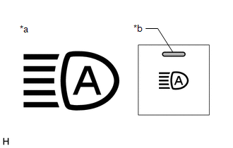
|
*a | Automatic High Beam Indicator Light on Combination Meter Assembly |
|
*b | Auto High Beam Switch Indicator |
AUTOMATIC HIGH BEAM SYSTEM OPERATION CHECK
(a) Check the operation of the automatic high beam indicator light.
(1) Turn the engine switch on (IG).
(2) Turn the light control switch to the AUTO or head position.
(3) Move the dimmer switch to the high position.
(4) Press the auto high beam switch (indicator illuminates).
HINT:
If the auto high beam switch is turned on when the light control switch is not in the AUTO or head position, or the dimmer switch is not in the high position, "Auto High Beam Ready Turn ON High Beam to Activate" will be displayed on the multi-information display.
(5) Check that the automatic high beam indicator illuminates.
NOTICE:
When the forward recognition camera cannot correctly detect objects due to inclement weather such as thick fog or other visual obstructions, the automatic high beam indicator may not turn on and consequently the automatic high beam system may not operate.
(b) Check the operation of the automatic high beam function.
(1) At night, when driving the vehicle with the automatic high beam system in standby mode, check that the high beams automatically turn on after a short delay when all of the following conditions are met:
(2) At night, when driving the vehicle with the high beams turned on by the automatic high beam system, check that the automatic high beam system turns off the high beams and returns to standby mode when any of the following conditions are met:
DESCRIPTION
Parking light function:WIRING DIAGRAM
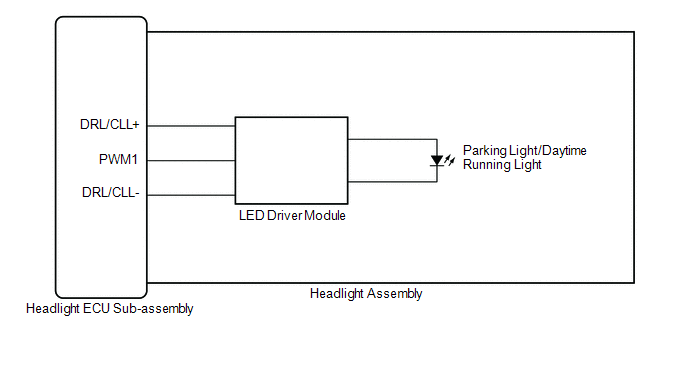
CAUTION / NOTICE / HINT
NOTICE:
Click here 
Click here
PROCEDURE
|
1. | CHECK LIGHTS |
(a) Check the illumination of each parking lights and daytime running lights.
|
Result | Proceed to |
|---|---|
|
LH side parking light and daytime running light does not illuminate |
A |
| RH side parking light and daytime running light does not illuminate |
B |
| B |
 | GO TO STEP 5 |
|
| 2. |
PERFORM ACTIVE TEST USING TECHSTREAM |
(a) Connect the Techstream to the DLC3.
(b) Turn the engine switch on (IG).
(c) Turn the Techstream on.
(d) Enter the following menus: Body Electrical / HL AutoLeveling / Active Test.
(e) Perform the Active Test according to the display on the Techstream.
Body Electrical > HL AutoLeveling > Active Test|
Tester Display | Measurement Item |
Control Range | Diagnostic Note |
|---|---|---|---|
|
Clearance Light | Parking lights |
OFF or ON | - |
|
Daytime Running Light | Daytime running lights |
OFF or ON | - |
|
Tester Display |
|---|
| Clearance Light |
|
Tester Display |
|---|
| Daytime Running Light |
OK:
Parking lights and daytime running lights illuminate.
| OK | | PROCEED TO NEXT SUSPECTED AREA SHOWN IN PROBLEM SYMPTOMS TABLE |
|
| 3. |
CHECK HEADLIGHT ASSEMBLY LH |
(a) Remove each headlight ECU sub-assembly, interchange the headlight assembly LH with RH and connect the connectors.
Click here
|
| 4. |
CHECK OPERATION (PARKING LIGHTS AND DAYTIME RUNNING LIGHTS) |
(a) Check the operation of the parking lights and daytime running lights.
OK:
The parking lights and daytime running lights operate normally.
| OK | | REPLACE HEADLIGHT ECU SUB-ASSEMBLY LH |
| NG | | REPLACE HEADLIGHT ASSEMBLY LH |
| 5. |
PERFORM ACTIVE TEST USING TECHSTREAM |
(a) Connect the Techstream to the DLC3.
(b) Turn the engine switch on (IG).
(c) Turn the Techstream on.
(d) Enter the following menus: Body Electrical / HL AutoLeveling (Sub) / Active Test.
(e) Perform the Active Test according to the display on the Techstream.
Body Electrical > HL AutoLeveling (Sub) > Active Test|
Tester Display | Measurement Item |
Control Range | Diagnostic Note |
|---|---|---|---|
|
Clearance Light | Parking lights |
OFF or ON | - |
|
Daytime Running Light | Daytime running lights |
OFF or ON | - |
|
Tester Display |
|---|
| Clearance Light |
|
Tester Display |
|---|
| Daytime Running Light |
OK:
Parking lights and daytime running lights illuminate.
| OK | | PROCEED TO NEXT SUSPECTED AREA SHOWN IN PROBLEM SYMPTOMS TABLE |
|
| 6. |
CHECK HEADLIGHT ASSEMBLY RH |
(a) Remove each headlight ECU sub-assembly, interchange the headlight assembly RH with LH and connect the connectors.
Click here
|
| 7. |
CHECK OPERATION (PARKING LIGHTS AND DAYTIME RUNNING LIGHTS) |
(a) Check the operation of the parking lights and daytime running lights.
OK:
The parking lights and daytime running lights operate normally.
| OK | | REPLACE HEADLIGHT ECU SUB-ASSEMBLY RH |
| NG | | REPLACE HEADLIGHT ASSEMBLY RH |
PARTS LOCATION
ILLUSTRATION
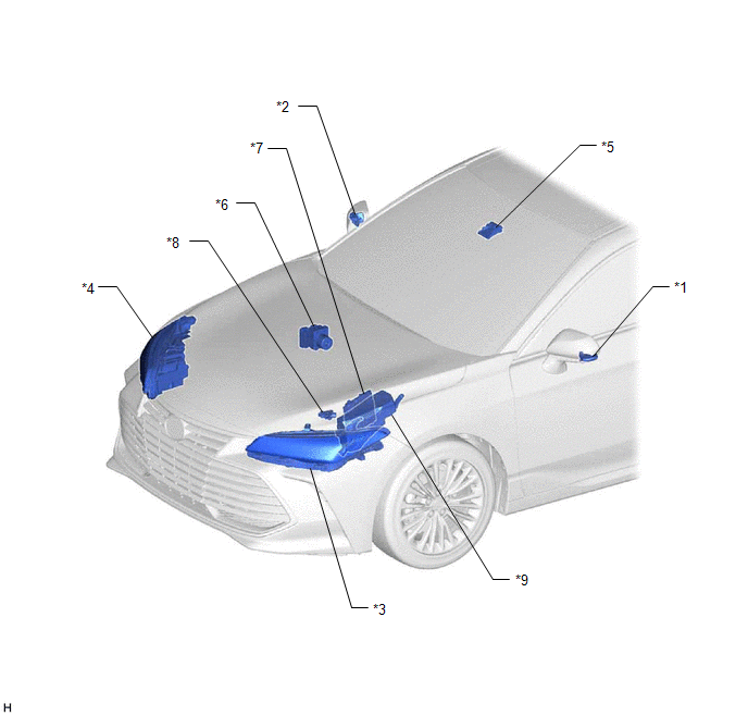
|
*1 | SIDE TURN SIGNAL LIGHT ASSEMBLY LH |
*2 | SIDE TURN SIGNAL LIGHT ASSEMBLY RH |
|
*3 | HEADLIGHT ASSEMBLY LH - HEADLIGHT ECU SUB-ASSEMBLY LH |
*4 | HEADLIGHT ASSEMBLY RH - HEADLIGHT ECU SUB-ASSEMBLY RH |
|
*5 | FORWARD RECOGNITION CAMERA |
*6 | SKID CONTROL ECU (BRAKE ACTUATOR ASSEMBLY) |
|
*7 | ECM |
*8 | PARK/NEUTRAL POSITION SWITCH ASSEMBLY |
|
*9 | NO. 1 ENGINE ROOM RELAY BLOCK AND NO. 1 JUNCTION BLOCK ASSEMBLY - H-LP LH RELAY - H-LP RH RELAY - H-LP LH FUSE - H-LP RH FUSE - ALT FUSE | - |
- |
ILLUSTRATION
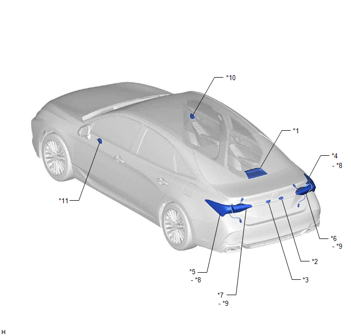
|
*1 | CENTER STOP LIGHT SET |
*2 | LICENSE PLATE LIGHT ASSEMBLY RH |
|
*3 | LICENSE PLATE LIGHT ASSEMBLY LH |
*4 | REAR COMBINATION LIGHT ASSEMBLY RH |
|
*5 | REAR COMBINATION LIGHT ASSEMBLY LH |
*6 | REAR LIGHT ASSEMBLY RH |
|
*7 | REAR LIGHT ASSEMBLY LH |
*8 | REAR COMBINATION LIGHT SOCKET AND WIRE |
|
*9 | REAR LIGHT CORD |
*10 | OUTER MIRROR CONTROL ECU ASSEMBLY RH |
|
*11 | OUTER MIRROR CONTROL ECU ASSEMBLY LH |
- | - |
ILLUSTRATION
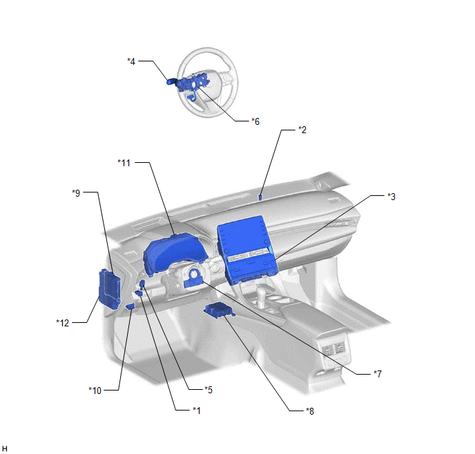
|
*1 | AUTO HIGH BEAM SWITCH |
*2 | AUTOMATIC LIGHT CONTROL SENSOR |
|
*3 | HAZARD WARNING SIGNAL SWITCH (RADIO AND DISPLAY RECEIVER ASSEMBLY) |
*4 | TURN SIGNAL SWITCH |
|
*5 | STOP LIGHT SWITCH ASSEMBLY |
*6 | STEERING WHEEL SWITCH HOUSING |
|
*7 | STEERING SENSOR |
*8 | AIRBAG ECU ASSEMBLY |
|
*9 | MAIN BODY ECU (MULTIPLEX NETWORK BODY ECU) |
*10 | DLC3 |
|
*11 | COMBINATION METER ASSEMBLY |
*12 | INSTRUMENT PANEL JUNCTION BLOCK ASSEMBLY - TAIL RELAY - BKUP LP RELAY - TAIL FUSE - BKUP LP FUSE - ECU-IG1 NO. 3 FUSE - ECU-B NO. 2 FUSE - ECU-DCC NO. 2 FUSE - HAZ FUSE - METER-IG2 FUSE - STOP FUSE - ECU-ACC FUSE |
PRECAUTION
PRECAUTION FOR DISCONNECTING CABLE FROM NEGATIVE BATTERY TERMINAL
NOTICE:
When disconnecting the cable from the negative (-) battery terminal, initialize the following systems after the cable is reconnected.
|
System Name | See Procedure |
|---|---|
|
Lane Departure Alert System (w/ Steering Control) |
|
|
Intelligent Clearance Sonar System | |
|
Parking Assist Monitor System | |
|
Panoramic View Monitor System | |
|
Pre-collision System | |
|
Lighting System (for Gasoline Model with Cornering Light) |
PRECAUTIONS FOR LIGHTING SYSTEM
(a) If the headlight ECU sub-assembly LH has been replaced, it is necessary to synchronize the vehicle information the headlight ECU sub-assembly LH.
Click here 
(b) If the headlight assembly LH has been replaced, it is necessary to synchronize the vehicle information the headlight ECU sub-assembly LH.
Click here
PRECAUTION FOR AUTOMATIC HIGH BEAM SYSTEM
(a) General Description
The automatic high beam system is a system that helps ensure visibility by automatically turning the high beam headlights on and off. Additionally, due to control limitations of the automatic high beam system, it may be necessary to manually turn the high beam headlights on and off. For safety reasons, make sure to turn the high beam headlights on and off manually according to the driving conditions.
(b) Conditions Unsuitable for Using Automatic High Beam System
Under the following conditions, the automatic high beam system might not detect other vehicles or lights correctly, or the high beam headlights might cause glare or flash pedestrians or the occupants of other vehicles. Manual operation should be considered.
|
Factor | Condition |
|---|---|
|
Weather/Climate | When driving in bad weather (rain, snow, fog, sandstorms, etc.). |
|
Front windshield |
|
| Forward recognition camera |
|
| Nearby vehicles or lights |
|
| Road conditions |
|
| Own vehicle |
|
| Automatic high beam system |
Malfunction: When the automatic high beam indicator light on the combination meter assembly is off and "Headlight System Malfunction Visit Your Dealer" is displayed on the multi-information display. Others:
|
PRECAUTION FOR FRONT CAMERA SYSTEM
Click here
PROBLEM SYMPTOMS TABLE
NOTICE:
Click here 
Click here
Click here
HINT:
Use the table below to help determine the cause of problem symptoms. If multiple suspected areas are listed, the potential causes of the symptoms are listed in order of probability in the "Suspected Area" column of the table. Check each symptom by checking the suspected areas in the order they are listed. Replace parts as necessary.
Headlight|
Symptom | Suspected Area |
Link |
|---|---|---|
|
Left low beam headlight does not illuminate |
Headlight ECU sub-assembly LH |
|
|
Headlight assembly LH |
| |
|
Right low beam headlight does not illuminate |
Headlight ECU sub-assembly RH |
|
|
Headlight assembly RH |
| |
|
Both left and right low beam headlights do not illuminate |
Headlight dimmer switch circuit |
|
|
Main body ECU (Multiplex network body ECU) |
| |
|
Left high beam headlight does not illuminate |
High beam headlight circuit |
|
|
Headlight assembly LH |
| |
|
Right high beam headlight does not illuminate |
High beam headlight circuit |
|
|
Headlight assembly RH |
| |
|
Both left and right high beam headlights do not illuminate |
Headlight dimmer switch circuit |
|
|
Main body ECU (Multiplex network body ECU) |
| |
|
High Flash (passing function) does not operate (high beam headlights are normal) |
Headlight dimmer switch circuit |
|
|
Main body ECU (Multiplex network body ECU) |
| |
|
Left low beam headlight and high beam headlight do not illuminate |
Headlight ECU sub-assembly LH |
|
|
Right low beam headlight and high beam headlight do not illuminate |
Headlight ECU sub-assembly RH |
|
|
Symptom | Suspected Area |
Link |
|---|---|---|
|
Left parking light/daytime running light does not illuminate |
Parking light/daytime running light circuit |
|
|
Headlight ECU sub-assembly LH |
| |
|
Right parking light/daytime running light does not illuminate |
Parking light/daytime running light circuit |
|
|
Headlight ECU sub-assembly RH |
| |
|
Both left and right parking lights do not illuminate |
Headlight dimmer switch circuit |
|
|
Main body ECU (Multiplex network body ECU) |
| |
|
Both left and right daytime running lights do not illuminate |
Check customize settings |
|
|
Headlight dimmer switch circuit |
| |
|
Main body ECU (Multiplex network body ECU) |
|
|
Symptom | Suspected Area |
Link |
|---|---|---|
|
Left cornering light does not illuminate |
Check operating conditions |
|
|
Cornering light circuit |
| |
|
Headlight ECU sub-assembly LH |
| |
|
Right cornering light does not illuminate |
Check operating conditions |
|
|
Cornering light circuit |
| |
|
Headlight ECU sub-assembly RH |
|
|
Symptom | Suspected Area |
Link |
|---|---|---|
|
Left front side marker light does not illuminate |
Front side marker light circuit |
|
|
Headlight ECU sub-assembly LH |
| |
|
Right front side marker light does not illuminate |
Front side marker light circuit |
|
|
Headlight ECU sub-assembly RH |
| |
|
Both left and right front side marker lights do not illuminate |
Headlight dimmer switch circuit |
|
|
Main body ECU (Multiplex network body ECU) |
|
|
Symptom | Suspected Area |
Link |
|---|---|---|
|
Left or right taillight (rear combination light assembly) does not illuminate |
Rear combination light assembly |
|
|
Rear combination light socket and wire |
| |
|
Harness or connector |
- | |
|
Left or right taillight (rear light assembly) does not illuminate |
Rear light assembly |
|
|
Rear light cord |
| |
|
Harness or connector |
- | |
|
All of the taillights, license plate lights and rear side marker lights do not illuminate |
Headlight dimmer switch circuit |
|
|
Taillight relay circuit |
| |
|
Main body ECU (Multiplex network body ECU) |
|
|
Symptom | Suspected Area |
Link |
|---|---|---|
|
Left or right rear side marker light does not illuminate |
Rear combination light assembly |
|
|
Rear combination light socket and wire |
|
|
Symptom | Suspected Area |
Link |
|---|---|---|
|
License plate light does not illuminate |
License plate light assembly |
|
|
Harness or connector |
- |
|
Symptom | Suspected Area |
Link |
|---|---|---|
|
Left or right stop light (rear combination light assembly) does not illuminate |
Rear combination light assembly |
|
|
Rear combination light socket and wire |
| |
|
Harness or connector |
- | |
|
Left or right stop light (rear light assembly) does not illuminate |
Rear light assembly |
|
|
Rear light cord |
| |
|
Harness or connector |
- | |
|
All of the stop lights do not illuminate |
STOP fuse | - |
|
Stop light switch assembly |
| |
|
Harness or connector |
- |
|
Symptom | Suspected Area |
Link |
|---|---|---|
|
High mounted stop light does not illuminate |
Center stop light set |
|
|
Harness or connector |
- |
|
Symptom | Suspected Area |
Link |
|---|---|---|
|
Left or right back-up light does not illuminate |
Rear light assembly |
|
|
Rear light cord |
| |
|
Harness or connector |
- | |
|
Both left and right back-up lights do not illuminate |
BKUP LP fuse | - |
|
ECU-ACC fuse | - | |
|
Park/neutral position switch assembly |
| |
|
Instrument panel junction block assembly |
| |
|
Harness or connector |
- |
|
Symptom | Suspected Area |
Link |
|---|---|---|
|
Left or right front turn signal light does not operate |
Headlight ECU sub-assembly |
|
|
Headlight assembly |
| |
|
Harness or connector |
- | |
|
Left or right rear turn signal light does not operate |
Rear combination light assembly |
|
|
Rear combination light socket and wire |
| |
|
Rear light assembly |
| |
|
Rear light cord |
| |
|
Harness or connector |
- | |
|
Left or right side turn signal light does not operate |
Side turn signal light assembly |
|
|
Outer rear view mirror assembly |
| |
|
Outer mirror control ECU assembly |
| |
|
Harness or connector |
- | |
|
Turn signal lights do not operate in one direction |
Turn signal switch circuit |
|
|
Meter/gauge system |
| |
|
All turn signal lights do not operate |
Turn signal switch circuit |
|
|
Combination meter assembly |
| |
|
All turn signal lights do not flash at the correct speed |
Combination meter assembly |
|
|
Symptom | Suspected Area |
Link |
|---|---|---|
|
Hazard warning signal lights do not operate |
Hazard warning switch circuit |
|
|
Combination meter assembly |
|
|
Symptom | Suspected Area |
Link |
|---|---|---|
|
Automatic light control system does not operate |
Headlight dimmer switch circuit |
|
|
Main body ECU (Multiplex network body ECU) |
|
|
Symptom | Suspected Area |
Link |
|---|---|---|
|
Light auto turn-off system does not operate |
Headlight dimmer switch circuit |
|
|
IG signal circuit |
| |
|
Front door courtesy switch circuit |
| |
|
Main body ECU (Multiplex network body ECU) |
|
|
Symptom | Suspected Area |
Link |
|---|---|---|
| Lights do not operate using remote operation function (lighting system is normal) |
Telematics system |
|
|
Symptom | Suspected Area |
Link |
|---|---|---|
|
Wiper-linked low beam headlight control system does not operate |
Check customize settings |
|
|
Main body ECU (Multiplex network body ECU) |
|
|
Symptom | Suspected Area |
Link |
|---|---|---|
|
Welcome light illumination control does not operate |
Check customize settings |
|
|
Main body ECU (Multiplex network body ECU) |
|
|
Symptom | Suspected Area |
Link |
|---|---|---|
|
Automatic high beam system does not operate or automatic high beam indicator does not illuminate (low beam headlights and high beam headlights are normal) | Check millimeter wave radar sensor assembly |
|
|
Check Data List (High Temperature Status1) | ||
|
Check automatic high beam indicator light | ||
|
Check Data List (Auto H Beam STS0) | ||
|
Perform Active Test (Multi Display All (White)) | ||
|
Auto high beam switch | ||
|
Harness or connector | ||
|
Combination meter assembly | ||
|
Forward recognition camera | ||
|
Main body ECU (Multiplex network body ECU) | ||
|
Auto high beam switch indicator does not come ON |
Refer to "Automatic High Beam Switch Indicator does not Come ON" |
|
SYSTEM DIAGRAM
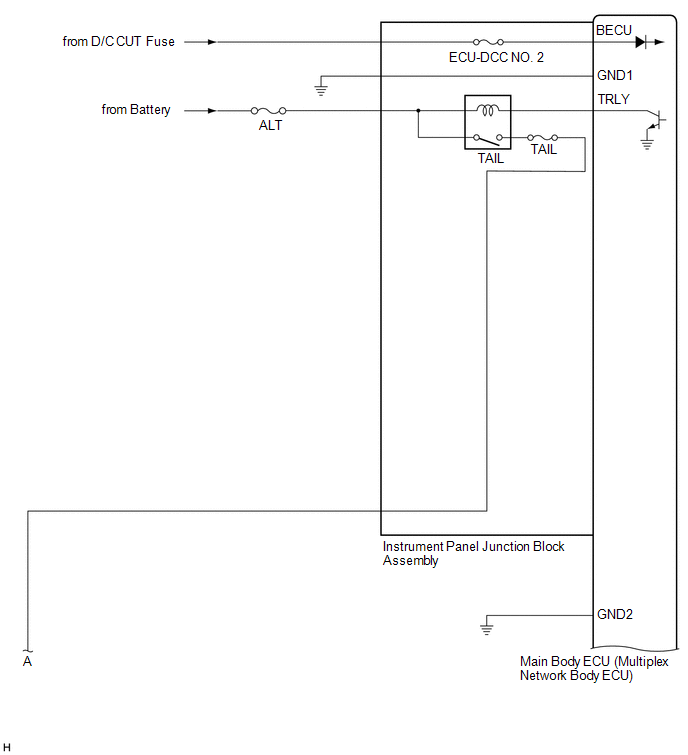
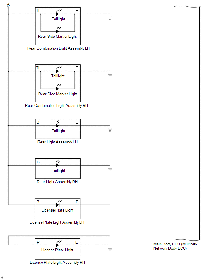
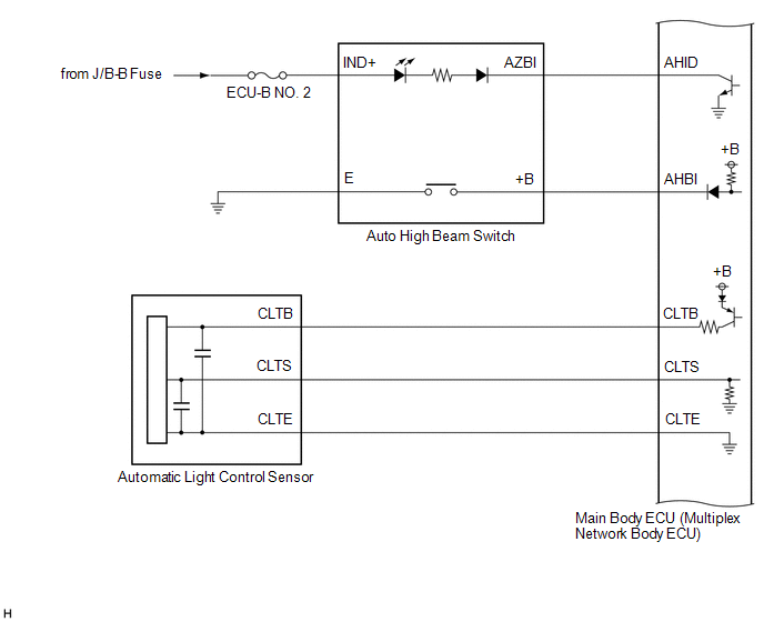
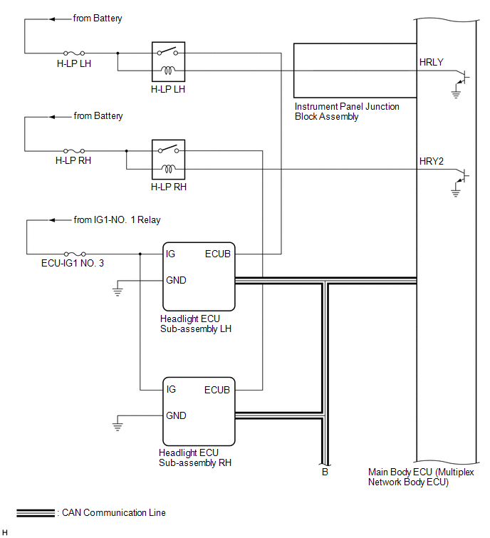
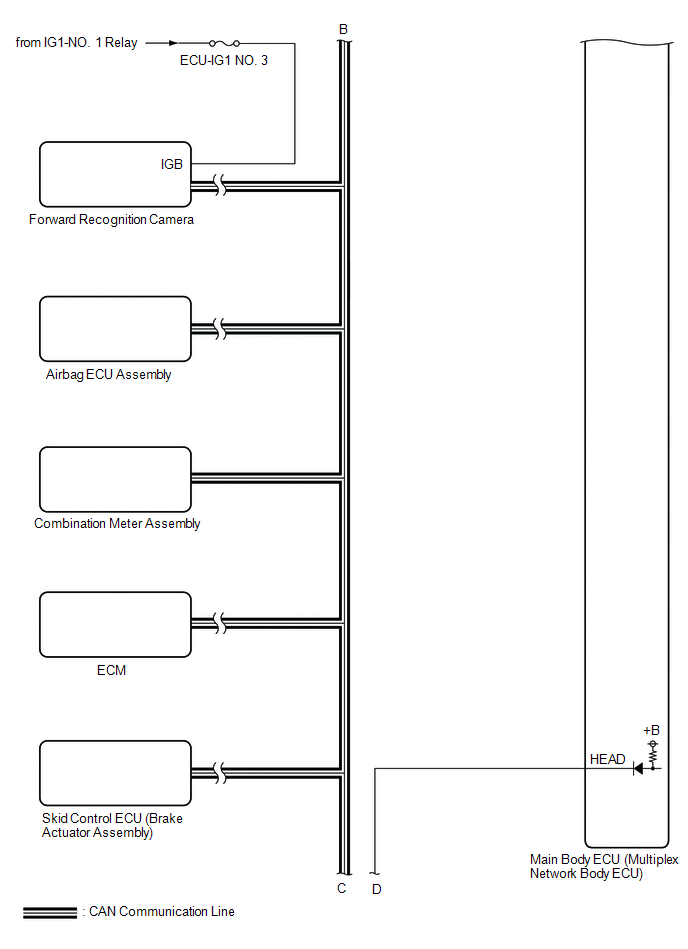
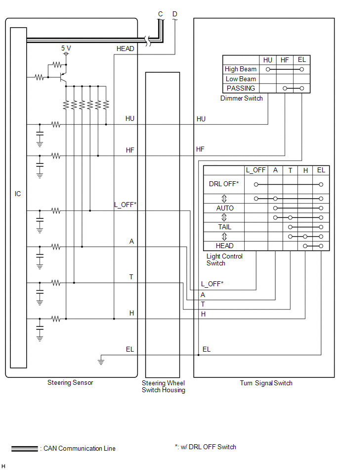
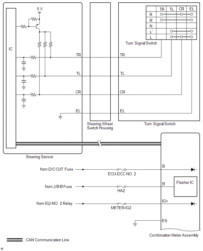
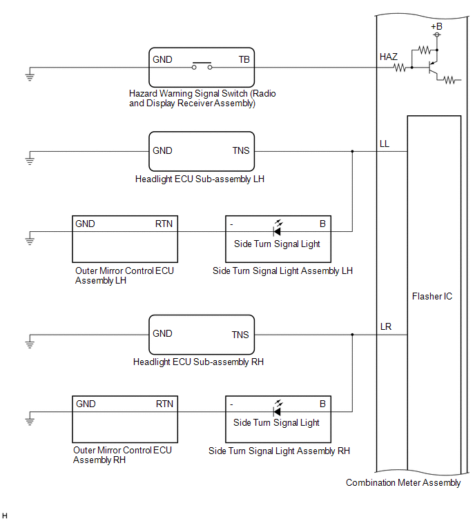
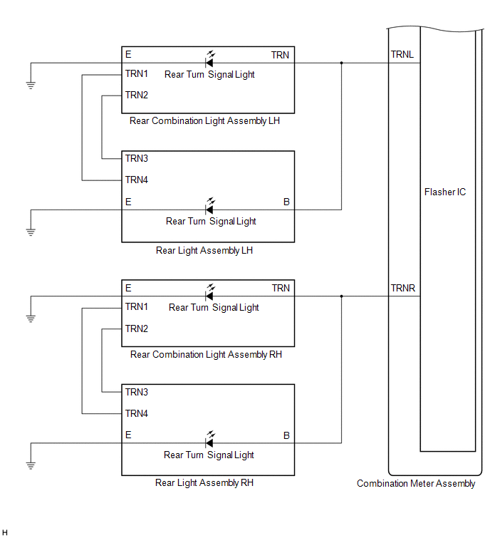
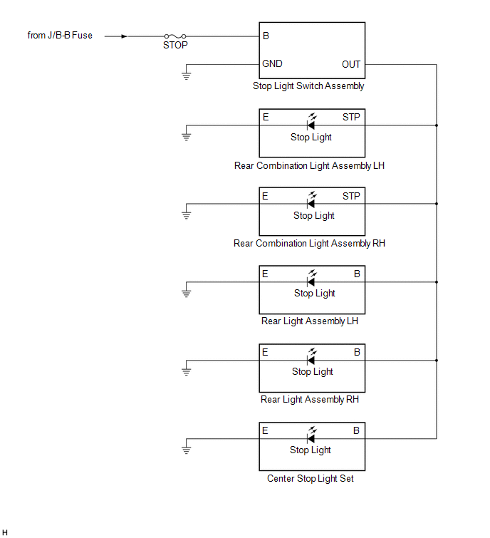
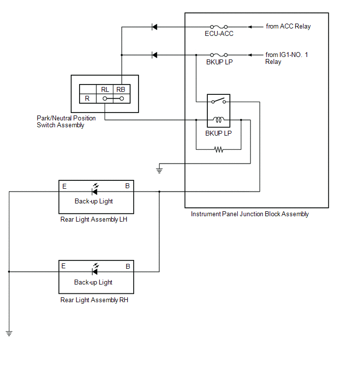
HEADLIGHT ASSEMBLY CIRCUIT
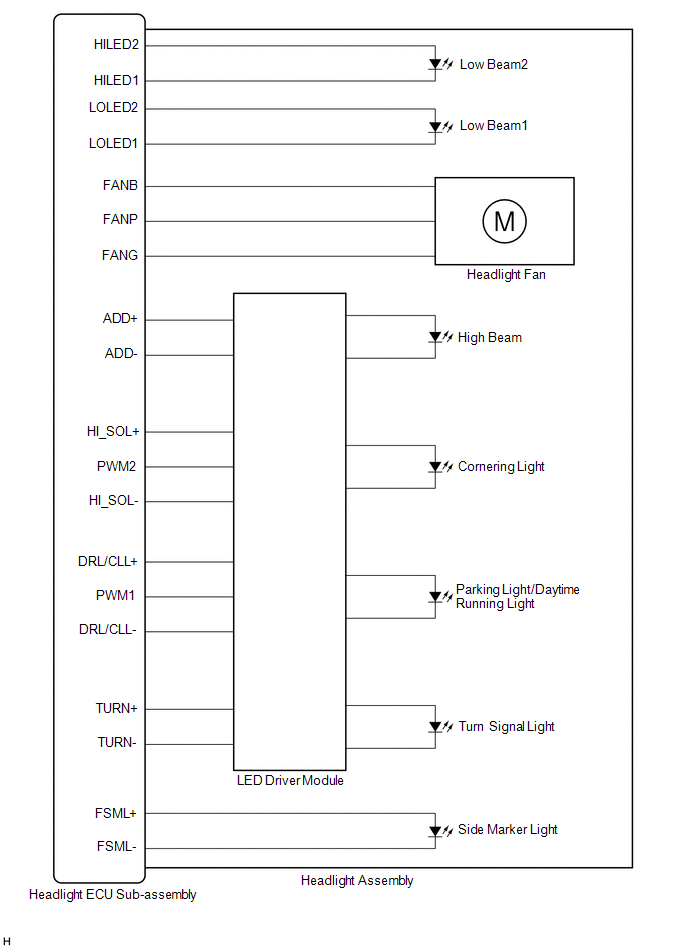
DESCRIPTION
The main body ECU (multiplex network body ECU) controls the operation of the TAIL relay.
WIRING DIAGRAM
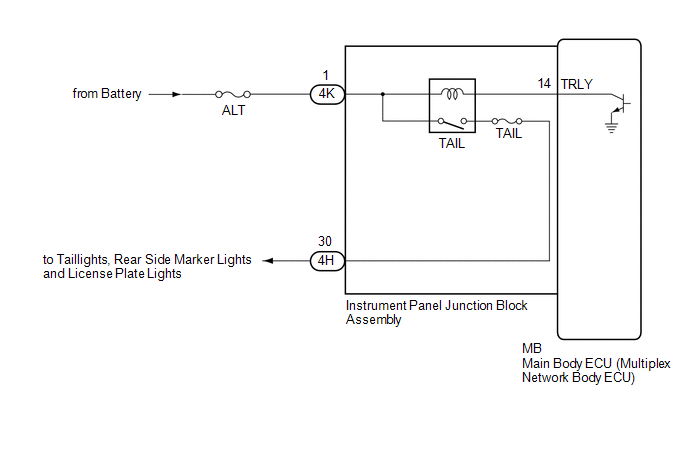
CAUTION / NOTICE / HINT
NOTICE:
Click here 
PROCEDURE
|
1. | PERFORM ACTIVE TEST USING TECHSTREAM |
(a) Connect the Techstream to the DLC3.
(b) Turn the engine switch on (IG).
(c) Turn the Techstream on.
(d) Enter the following menus: Body Electrical / Main Body / Active Test.
(e) Perform the Active Test according to the display on the Techstream.
Body Electrical > Main Body > Active Test|
Tester Display | Measurement Item |
Control Range | Diagnostic Note |
|---|---|---|---|
|
Taillight Relay | Taillight relay |
OFF or ON | - |
|
Tester Display |
|---|
| Taillight Relay |
OK:
Taillights illuminate.
| OK |  | PROCEED TO NEXT SUSPECTED AREA SHOWN IN PROBLEM SYMPTOMS TABLE |
|
| 2. |
CHECK HARNESS AND CONNECTOR (POWER SOURCE - INSTRUMENT PANEL JUNCTION BLOCK ASSEMBLY) |
(a) Disconnect the 4K instrument panel junction block assembly connector.
(b) Measure the voltage according to the value(s) in the table below.
Standard Voltage:
|
Tester Connection | Condition |
Specified Condition |
|---|---|---|
|
4K-1 - Body ground | Always |
11 to 14 V |
| NG | | REPAIR OR REPLACE HARNESS OR CONNECTOR |
|
| 3. |
INSPECT INSTRUMENT PANEL JUNCTION BLOCK ASSEMBLY |
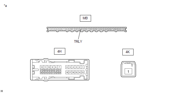
|
*a | Component without harness connected (Instrument Panel Junction Block Assembly) |
- | - |
(a) Remove the main body ECU (multiplex network body ECU) from the instrument panel junction block assembly.
Click here
(b) Connect a positive (+) lead from the battery to terminal 4K-1.
(c) Connect a negative (-) lead from the battery to terminal MB-14 (TRLY).
(d) Measure the voltage according to the value(s) in the table below.
Standard Voltage:
|
Tester Connection | Condition |
Specified Condition |
|---|---|---|
|
4H-30 - Battery negative (-) terminal |
Always | 11 to 14 V |
| OK | | REPLACE MAIN BODY ECU (MULTIPLEX NETWORK BODY ECU) |
| NG | | REPLACE INSTRUMENT PANEL JUNCTION BLOCK ASSEMBLY |
TERMINALS OF ECU
CHECK MAIN BODY ECU (MULTIPLEX NETWORK BODY ECU) AND INSTRUMENT PANEL JUNCTION BLOCK ASSEMBLY
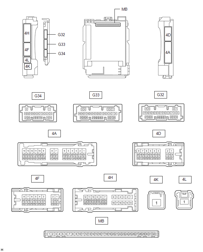
(a) Disconnect the instrument panel junction block assembly and main body ECU (multiplex network body ECU) connectors.
(b) Measure the voltage and resistance according to the value(s) in the table below.
|
Terminal No. (Symbol) | Wiring Color |
Terminal Description | Condition |
Specified Condition |
|---|---|---|---|---|
|
4D-3 - Body ground | LA - Body ground |
Ground | Always |
Below 1 Ω |
|
4F-1 - Body ground | LG - Body ground |
Battery power supply | Always |
11 to 14 V |
|
4K-1 - Body ground | B - Body ground |
Battery power supply | Always |
11 to 14 V |
(c) Connect the instrument panel junction block assembly and main body ECU (multiplex network body ECU) connectors.
(d) Measure the voltage and resistance, and check for pulses according to the value(s) in the table below.
|
Terminal No. (Symbol) | Wiring Color |
Terminal Description | Condition |
Specified Condition |
|---|---|---|---|---|
|
4F-19 - Body ground |
BE - Body ground |
BKUP LP relay drive output |
Engine switch off, reverse (R) not selected |
Below 1 V |
| Engine switch on (IG), reverse (R) selected |
11 to 14 V | |||
|
4F-31 - Body ground |
V - Body ground | H-LP LH relay drive output |
| Below 1 V |
| 11 to 14 V | |||
|
4H-10 - Body ground |
LG - Body ground |
Back-up lights drive output |
Engine switch off, reverse (R) not selected |
Below 1 V |
| Engine switch on (IG), reverse (R) selected |
11 to 14 V | |||
|
4H-30 - Body ground |
LA-B - Body ground |
Taillights, rear side marker lights and license plate lights drive output |
Taillights on | 11 to 14 V |
|
Taillights off | Below 1 V | |||
|
G32-19 (GND2) - Body ground |
W-B - Body ground | Ground |
Always | Below 1 Ω |
|
G32-23 (AHID) - Body ground |
BE - Body ground |
Auto high beam switch indicator drive output |
Engine switch on (IG), auto high beam switch on |
Below 1 V |
| Engine switch on (IG), auto high beam switch off |
11 to 14 V | |||
|
G33-12 (HRY2) - Body ground |
BE - Body ground | H-LP RH relay drive output |
| Below 1 V |
| 11 to 14 V | |||
|
G33-16 (HEAD) - Body ground |
LG - Body ground | Light control switch head position input |
Light control switch in head position |
Below 1 V |
| Light control switch not in head position |
11 to 14 V | |||
|
G33-23 (CLTB) - G33-25 (CLTE) |
BE - GR | Automatic light control sensor power supply output |
Engine switch off | Below 1 V |
|
Engine switch on (IG) |
11 to 14 V | |||
|
G33-24 (CLTS) - Body ground |
R - Body ground |
Automatic light control sensor signal input |
Engine switch off | Below 1 V |
|
Engine switch on (IG) |
Pulse generation (See waveform 1) | |||
|
G33-26 (AHBI) - Body ground |
B - Body ground | Auto high beam switch signal input |
Auto high beam switch on |
Below 1 V |
| Auto high beam switch off |
11 to 14 V |
(1) Waveform 1

|
Item | Content |
|---|---|
|
Tester Connection | G33-24 (CLTS) - Body ground |
|
Tool setting | 2 V/DIV., 10 ms./DIV. |
|
Condition | Engine switch on (IG) |
HINT:
The communication waveform changes according to the surrounding brightness.
CHECK HEADLIGHT ECU SUB-ASSEMBLY LH
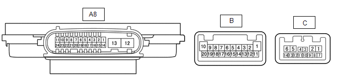
(a) Disconnect the A8 headlight ECU sub-assembly LH connector.
(b) Measure the voltage and resistance on the wire harness side connector according to the value(s) in the table below.
|
Terminal No. (Symbol) | Wiring Color |
Terminal Description | Condition |
Specified Condition |
|---|---|---|---|---|
|
A8-4 (IG) - Body ground |
B - Body ground |
Ignition power supply | Engine switch off |
Below 1 V |
| Engine switch on (IG) |
11 to 14 V | |||
|
A8-12 (GND) - Body ground |
W-B - Body ground | Ground |
Always | Below 1 Ω |
|
A8-13 (ECUB) - Body ground |
B - Body ground |
Battery power supply |
| Below 1 V |
| 9.5 to 14 V |
(c) Connect the A8 headlight ECU sub-assembly LH connector.
HINT:
(d) Measure the voltage and check of pulses according to the value(s) in the table below.
|
Terminal No. (Symbol) | Wiring Color |
Terminal Description | Condition |
Specified Condition |
|---|---|---|---|---|
|
A8-11 (TNS) - Body ground |
LA-LG - Body ground |
Front turn signal light signal input |
Engine switch on (IG), front turn signal light off |
Below 1 V |
| Engine switch on (IG), front turn signal light blinking |
11 to 14 V ←→ Below 1 V | |||
|
A8-23 (CANL) - Body ground |
W - Body ground |
CAN communication line |
Engine switch off | Below 1 V |
|
Engine switch on (IG) |
Pulse generation | |||
|
A8-24 (CANH) - Body ground |
P - Body ground |
CAN communication line |
Engine switch off | Below 1 V |
|
Engine switch on (IG) |
Pulse generation | |||
|
B-2 (LOLED2) - B-3 (LOLED1) |
- | Low beam headlights drive output |
Low beam headlights off |
Below 1 V |
| Low beam headlights on |
19.2 to 27.9 V | |||
|
B-6 (HILED2) - B-5 (HILED1) |
- | Low beam headlights drive output |
Low beam headlights off |
Below 1 V |
| Low beam headlights on |
15.5 to 24.0 V | |||
|
B-4 (FANB) - B-14 (FANG) |
- | Headlight fan power source |
Low beam headlights off |
Below 1 V |
| Low beam headlights on |
4.75 to 5.25 V | |||
|
B-10 (DRL/CLL+) - B-1 (DRL/CLL-) |
- | Parking lights/daytime running lights power source |
Parking lights and daytime running lights off |
Below 1 V |
| Parking lights and daytime running lights on |
11 to 14 V | |||
|
B-15 (FANP) - B-14 (FANG) |
- | Headlight fan control signal input |
Low beam headlights off |
Below 1 V |
| Low beam headlights on |
Pulse generation | |||
|
B-16 (PWM1) - B-1 (DRL/CLL-) |
- | Parking lights/daytime running lights control signal output |
Parking lights and daytime running lights off |
Below 1 V |
| Parking lights and daytime running lights on |
Pulse generation | |||
|
B-18 (FSML+) - B-12 (FSML-) |
- | Front side marker light drive output |
Front side marker light off |
Below 1 V |
| Front side marker light on |
11 to 14 V | |||
|
B-19 (HI_SOL+) - B-11 (HI_SOL-) |
- | Cornering light power source |
Cornering light off | Below 1 V |
|
Cornering light on | 11 to 14 V | |||
|
B-20 (TURN+) - B-13 (TURN-) |
- | Front turn signal light signal output |
Engine switch on (IG), front turn signal light off |
Below 1 V |
| Engine switch on (IG), front turn signal light blinking |
11 to 14 V ←→ Below 1 V | |||
|
C-6 (ADD+) - C-1 (ADD-) |
- | High beam headlights drive output |
High beam headlights off |
Below 1 V |
| High beam headlights on |
11 to 14 V | |||
|
C-12 (PWM2) - B-11 (HI_SOL-) |
- | Cornering light control signal output |
Cornering light off | Below 1 V |
|
Cornering light on | Pulse generation |
CHECK HEADLIGHT ECU SUB-ASSEMBLY RH

(a) Disconnect the A9 headlight ECU sub-assembly RH connector.
(b) Measure the voltage and resistance on the wire harness side connector according to the value(s) in the table below.
|
Terminal No. (Symbol) | Wiring Color |
Terminal Description | Condition |
Specified Condition |
|---|---|---|---|---|
|
A9-4 (IG) - Body ground |
B - Body ground |
Ignition power supply | Engine switch off |
Below 1 V |
| Engine switch on (IG) |
11 to 14 V | |||
|
A9-12 (GND) - Body ground |
W-B - Body ground | Ground |
Always | Below 1 Ω |
|
A9-13 (ECUB) - Body ground |
R - Body ground |
Battery power supply |
| Below 1 V |
| 9.5 to 14 V |
(c) Connect the A9 headlight ECU sub-assembly RH connector.
HINT:
(d) Measure the voltage and check of pulses according to the value(s) in the table below.
|
Terminal No. (Symbol) | Wiring Color |
Terminal Description | Condition |
Specified Condition |
|---|---|---|---|---|
|
A9-11 (TNS) - Body ground |
LA-G - Body ground |
Front turn signal light signal input |
Engine switch on (IG), front turn signal light off |
Below 1 V |
| Engine switch on (IG), front turn signal light blinking |
11 to 14 V ←→ Below 1 V | |||
|
A9-23 (CANL) - Body ground |
W - Body ground |
CAN communication line |
Engine switch off | Below 1 V |
|
Engine switch on (IG) |
Pulse generation | |||
|
A9-24 (CANH) - Body ground |
L - Body ground |
CAN communication line |
Engine switch off | Below 1 V |
|
Engine switch on (IG) |
Pulse generation | |||
|
B-2 (LOLED2) - B-3 (LOLED1) |
- | Low beam headlights drive output |
Low beam headlights off |
Below 1 V |
| Low beam headlights on |
19.2 to 27.9 V | |||
|
B-6 (HILED2) - B-5 (HILED1) |
- | Low beam headlights drive output |
Low beam headlights off |
Below 1 V |
| Low beam headlights on |
15.5 to 24.0 V | |||
|
B-4 (FANB) - B-14 (FANG) |
- | Headlight fan power source |
Low beam headlights off |
Below 1 V |
| Low beam headlights on |
4.75 to 5.25 V | |||
|
B-10 (DRL/CLL+) - B-1 (DRL/CLL-) |
- | Parking lights/daytime running lights power source |
Parking lights and daytime running lights off |
Below 1 V |
| Parking lights and daytime running lights on |
11 to 14 V | |||
|
B-15 (FANP) - B-14 (FANG) |
- | Headlight fan control signal input |
Low beam headlights off |
Below 1 V |
| Low beam headlights on |
Pulse generation | |||
|
B-16 (PWM1) - B-1 (DRL/CLL-) |
- | Parking lights/daytime running lights control signal output |
Parking lights and daytime running lights off |
Below 1 V |
| Parking lights and daytime running lights on |
Pulse generation | |||
|
B-18 (FSML+) - B-12 (FSML-) |
- | Front side marker light drive output |
Front side marker light off |
Below 1 V |
| Front side marker light on |
11 to 14 V | |||
|
B-19 (HI_SOL+) - B-11 (HI_SOL-) |
- | Cornering light power source |
Cornering light off | Below 1 V |
|
Cornering light on | 11 to 14 V | |||
|
B-20 (TURN+) - B-13 (TURN-) |
- | Front turn signal light signal output |
Engine switch on (IG), front turn signal light off |
Below 1 V |
| Engine switch on (IG), front turn signal light blinking |
11 to 14 V ←→ Below 1 V | |||
|
C-6 (ADD+) - C-1 (ADD-) |
- | High beam headlights drive output |
High beam headlights off |
Below 1 V |
| High beam headlights on |
11 to 14 V | |||
|
C-12 (PWM2) - B-11 (HI_SOL-) |
- | Cornering light control signal output |
Cornering light off | Below 1 V |
|
Cornering light on | Pulse generation |
CHECK COMBINATION METER ASSEMBLY
Click here

CHECK FORWARD RECOGNITION CAMERA
Click here
CHECK STEERING SENSOR
Click here
DESCRIPTION
The steering sensor receives the turn signal switch information and controls the turn signal lights.
WIRING DIAGRAM
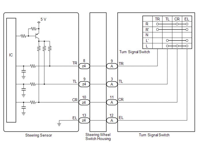
PROCEDURE
| 1. |
READ VALUE USING TECHSTREAM |
(a) Connect the Techstream to the DLC3.
(b) Turn the engine switch on (IG).
(c) Turn the Techstream on.
(d) Enter the following menus: Chassis / Steering Angle Sensor / Data List.
(e) Read the Data List according to the display on the Techstream.
Chassis > Steering Angle Sensor > Data List|
Tester Display | Measurement Item |
Range | Normal Condition |
Diagnostic Note |
|---|---|---|---|---|
|
Turn Signal Switch (Right) |
Turn signal switch (right turn position) signal |
OFF or ON | OFF: Turn signal switch not in right turn position ON: Turn signal switch in right turn position |
- |
| Turn Signal Switch (Left) |
Turn signal switch (left turn position) signal |
OFF or ON | OFF: Turn signal switch not in left turn position ON: Turn signal switch in left turn position |
- |
| Cornering Light/Front Side Illuminate Light Switch |
Turn signal switch (full turn) signal |
OFF or ON | OFF: Turn signal switch not in left or right turn position ON: Turn signal switch in left or right full turn position |
- |
|
Tester Display |
|---|
| Turn Signal Switch (Right) |
|
Turn Signal Switch (Left) |
|
Cornering Light/Front Side Illuminate Light Switch |
OK:
Normal conditions listed above are displayed.
| OK |  | PROCEED TO NEXT SUSPECTED AREA SHOWN IN PROBLEM SYMPTOMS TABLE |
|
| 2. |
INSPECT TURN SIGNAL SWITCH |
(a) Remove the turn signal switch.
Click here 
(b) Inspect the turn signal switch.
Click here
| NG | | REPLACE TURN SIGNAL SWITCH |
|
| 3. |
INSPECT STEERING WHEEL SWITCH HOUSING |
(a) Remove the steering wheel switch housing.
Click here
(b) Inspect the steering wheel switch housing.
Click here
| OK | | REPLACE STEERING SENSOR |
| NG | | REPLACE STEERING WHEEL SWITCH HOUSING |
DESCRIPTION
These DTCs are stored if a CAN communication malfunction occurs between the headlight ECU sub-assembly LH and other ECUs.
|
DTC No. | Detection Item |
DTC Detection Condition | Trouble Area |
DTC Output from |
|---|---|---|---|---|
|
U0073 | Control Module Communication Bus Off |
The headlight ECU sub-assembly LH does not send/receive data. |
CAN communication system |
Headlight ECU sub-assembly LH |
|
U0100 | Lost Communication with ECM / PCM "A" |
The headlight ECU sub-assembly LH does not receive data from the ECM for approximately 10 seconds or more. |
| Headlight ECU sub-assembly LH |
|
U0101 | Lost Communication with TCM |
The headlight ECU sub-assembly LH does not receive data from the ECM for approximately 10 seconds or more. |
| Headlight ECU sub-assembly LH |
|
U0126 | Lost Communication with Steering Angle Sensor Module |
The headlight ECU sub-assembly LH does not receive data from the steering sensor for approximately 10 seconds or more. |
| Headlight ECU sub-assembly LH |
|
U0129 | Lost Communication with Brake System Control Module |
The headlight ECU sub-assembly LH does not receive data from the skid control ECU (brake actuator assembly) for approximately 10 seconds or more. |
| Headlight ECU sub-assembly LH |
|
U0142 | Lost Communication with Body Control Module "B" |
The headlight ECU sub-assembly LH does not receive data from the main body ECU (multiplex network body ECU) for approximately 10 seconds or more. |
| Headlight ECU sub-assembly LH |
|
U0155 | Lost Communication with Instrument Panel Cluster (IPC) Control Module |
The headlight ECU sub-assembly LH does not receive data from the combination meter assembly for approximately 30 seconds or more. |
| Headlight ECU sub-assembly LH |
|
U0242 | Lost Communication With Headlamp Control Module "B" |
The headlight ECU sub-assembly LH does not receive data from the headlight ECU sub-assembly RH for approximately 10 seconds or more. |
| Headlight ECU sub-assembly LH |
PROCEDURE
| 1. |
CLEAR DTC |
(a) Connect the Techstream to the DLC3.
(b) Turn the engine switch on (IG).
(c) Turn the Techstream on.
(d) Enter the following menus: Body Electrical / HL AutoLeveling / Trouble Codes.
(e) Clear the DTCs.
Body Electrical > HL AutoLeveling > Clear DTCs
|
| 2. |
CHECK FOR DTC |
(a) Connect the Techstream to the DLC3.
(b) Turn the engine switch on (IG).
(c) Wait 35 seconds or more.
(d) Turn the Techstream on.
(e) Enter the following menus: Body Electrical / HL AutoLeveling / Trouble Codes.
(f) Check for DTCs.
Body Electrical > HL AutoLeveling > Trouble CodesOK:
DTCs are not output.
| OK |  |
USE SIMULATION METHOD TO CHECK |
| NG | | GO TO CAN COMMUNICATION SYSTEM |
DESCRIPTION
These DTCs are stored if a CAN communication malfunction occurs between the headlight ECU sub-assembly RH and other ECUs.
|
DTC No. | Detection Item |
DTC Detection Condition | Trouble Area |
DTC Output from |
|---|---|---|---|---|
|
U0073 | Control Module Communication Bus OFF |
The headlight ECU sub-assembly RH does not send/receive data. |
CAN communication system |
Headlight ECU sub-assembly RH |
|
U0126 | Lost Communication with Steering Angle Sensor Module |
The headlight ECU sub-assembly RH does not receive data from the steering sensor for approximately 10 seconds or more. |
| Headlight ECU sub-assembly RH |
|
U0142 | Lost Communication with Body Control Module "B" |
The headlight ECU sub-assembly RH does not receive data from the main body ECU (multiplex network body ECU) for approximately 10 seconds or more. |
| Headlight ECU sub-assembly RH |
|
U0155 | Lost Communication with Instrument Panel Cluster (IPC) Control Module |
The headlight ECU sub-assembly RH does not receive data from the combination meter assembly for approximately 30 seconds or more. |
| Headlight ECU sub-assembly RH |
|
U0182 | Lost Communication With Lighting Control Module Front |
The headlight ECU sub-assembly RH does not receive data from the headlight ECU sub-assembly LH for approximately 10 seconds or more. |
| Headlight ECU sub-assembly RH |
PROCEDURE
| 1. |
CLEAR DTC |
(a) Connect the Techstream to the DLC3.
(b) Turn the engine switch on (IG).
(c) Turn the Techstream on.
(d) Enter the following menus: Body Electrical / HL AutoLeveling (Sub) / Trouble Codes.
(e) Clear the DTCs.
Body Electrical > HL AutoLeveling (Sub) > Clear DTCs
|
| 2. |
CHECK FOR DTC |
(a) Connect the Techstream to the DLC3.
(b) Turn the engine switch on (IG).
(c) Wait 35 seconds or more.
(d) Turn the Techstream on.
(e) Enter the following menus: Body Electrical / HL AutoLeveling (Sub) / Trouble Codes.
(f) Check for DTCs.
Body Electrical > HL AutoLeveling (Sub) > Trouble CodesOK:
DTCs are not output.
| OK |  |
USE SIMULATION METHOD TO CHECK |
| NG | | GO TO CAN COMMUNICATION SYSTEM |
DESCRIPTION
These DTCs are stored if a CAN communication malfunction occurs between the main body ECU (multiplex network body ECU) and other ECUs.
|
DTC No. | Detection Item |
DTC Detection Condition | Trouble Area |
DTC Output from |
|---|---|---|---|---|
|
U0100 | Lost Communication With ECM/PCM "A" |
The main body ECU (multiplex network body ECU) does not receive data from the ECM for approximately 10 seconds or more. |
| Main body ECU (multiplex network body ECU) |
|
U0101 | Lost Communication with TCM |
The main body ECU (multiplex network body ECU) does not receive data from the ECM for approximately 10 seconds or more. |
| Main body ECU (multiplex network body ECU) |
|
U0120 | Lost Communication With Starter / Generator Control Module |
The main body ECU (multiplex network body ECU) does not receive data from the certification ECU (smart key ECU assembly) for approximately 10 seconds or more. |
| Main body ECU (multiplex network body ECU) |
|
U0126 | Lost Communication with Steering Angle Sensor Module |
The main body ECU (multiplex network body ECU) does not receive data from the steering sensor for approximately 10 seconds or more. |
| Main body ECU (multiplex network body ECU) |
|
U0129 | Lost Communication with Brake System Control Module |
The main body ECU (multiplex network body ECU) does not receive data from the skid control ECU (brake actuator assembly) for approximately 10 seconds or more. |
| Main body ECU (multiplex network body ECU) |
|
U0151 | Lost Communication with Restraints Control Module |
The main body ECU (multiplex network body ECU) does not receive data from the airbag ECU assembly for approximately 10 seconds or more. |
| Main body ECU (multiplex network body ECU) |
|
U0155 | Lost Communication with Instrument Panel Cluster (IPC) Control Module |
The main body ECU (multiplex network body ECU) does not receive data from the combination meter assembly for approximately 10 seconds or more. |
| Main body ECU (multiplex network body ECU) |
|
U0163 | Lost Communication with Navigation Control Module |
The main body ECU (multiplex network body ECU) does not receive data from the radio and display receiver assembly for approximately 10 seconds or more. |
| Main body ECU (multiplex network body ECU) |
|
U0164 | Lost Communication with HVAC Control Module |
The main body ECU (multiplex network body ECU) does not receive data from the air conditioning amplifier assembly for approximately 10 seconds or more. |
| Main body ECU (multiplex network body ECU) |
|
U0182 | Lost Communication with AFS |
The main body ECU (multiplex network body ECU) does not receive data from the headlight ECU sub-assembly LH for approximately 10 seconds or more. |
| Main body ECU (multiplex network body ECU) |
|
U0199 | Lost Communication with "Door Control Module A" |
The main body ECU (multiplex network body ECU) does not receive data from the outer mirror control ECU assembly RH for approximately 10 seconds or more. |
| Main body ECU (multiplex network body ECU) |
|
U0200 | Lost Communication with "Door Control Module B" |
The main body ECU (multiplex network body ECU) does not receive data from the outer mirror control ECU assembly LH for approximately 10 seconds or more. |
| Main body ECU (multiplex network body ECU) |
|
U0208 | Lost Communication with "Seat Control Module A" |
The main body ECU (multiplex network body ECU) does not receive data from the position control ECU assembly (driver seat) for approximately 10 seconds or more. |
| Main body ECU (multiplex network body ECU) |
|
U023A | Lost Communication With Image Processing Module "A" |
The main body ECU (multiplex network body ECU) does not receive data from the forward recognition camera for approximately 10 seconds or more. |
| Main body ECU (multiplex network body ECU) |
|
U0327 | Software Incompatibility with Vehicle Security Control Module |
The main body ECU (multiplex network body ECU) does not receive data from the certification ECU (smart key ECU assembly) for approximately 10 seconds or more. |
| Main body ECU (multiplex network body ECU) |
|
U1106 | Lost Communication with Electric Parking Brake Module |
The main body ECU (multiplex network body ECU) does not receive data from the skid control ECU (brake actuator assembly) for approximately 10 seconds or more. |
| Main body ECU (multiplex network body ECU) |
|
U1115 | Lost Communication with Tilt & Telescopic Module |
The main body ECU (multiplex network body ECU) does not receive data from the multiplex tilt and telescopic ECU for approximately 10 seconds or more. |
| Main body ECU (multiplex network body ECU) |
|
U1117 | Lost Communication with Accessory Gateway |
The main body ECU (multiplex network body ECU) does not receive data from the option connector (bus buffer ECU) for approximately 10 seconds or more. |
| Main body ECU (multiplex network body ECU) |
PROCEDURE
| 1. |
CLEAR DTC |
(a) Connect the Techstream to the DLC3.
(b) Turn the engine switch on (IG).
(c) Turn the Techstream on.
(d) Enter the following menus: Body Electrical / Main Body / Trouble Codes.
(e) Clear the DTCs.
Body Electrical > Main Body > Clear DTCs
|
| 2. |
CHECK FOR DTC |
(a) Connect the Techstream to the DLC3.
(b) Turn the engine switch on (IG).
(c) Wait 20 seconds or more.
(d) Turn the Techstream on.
(e) Enter the following menus: Body Electrical / Main Body / Trouble Codes.
(f) Check for DTCs.
Body Electrical > Main Body > Trouble CodesOK:
DTCs are not output.
| OK |  |
USE SIMULATION METHOD TO CHECK |
| NG | | GO TO CAN COMMUNICATION SYSTEM |
DESCRIPTION
The headlight ECU sub-assembly LH or headlight ECU sub-assembly RH stores this DTC if it detects an internal malfunction related to the CAN communication system.
HL AutoLeveling|
DTC No. | Detection Item |
DTC Detection Condition | Trouble Area |
DTC Output from |
|---|---|---|---|---|
|
U1000 | CAN Communication Failure (Message Registry) |
| Headlight ECU sub-assembly LH |
Headlight ECU sub-assembly LH |
|
DTC No. | Detection Item |
DTC Detection Condition | Trouble Area |
DTC Output from |
|---|---|---|---|---|
|
U1000 | CAN Communication Failure (Message Registry) |
| Headlight ECU sub-assembly RH |
Headlight ECU sub-assembly RH |
CAUTION / NOTICE / HINT
NOTICE:
If the headlight ECU sub-assembly LH has been replaced, it is necessary to synchronize the vehicle information the headlight ECU sub-assembly LH.
Click here

PROCEDURE
| 1. |
CLEAR DTC |
(a) Connect the Techstream to the DLC3.
(b) Turn the engine switch on (IG).
(c) Turn the Techstream on.
(d) Enter the following menus: Body Electrical / HL AutoLeveling or HL AutoLeveling (Sub) / Trouble Codes.
(e) Clear the DTCs.
Body Electrical > HL AutoLeveling > Clear DTCs Body Electrical > HL AutoLeveling (Sub) > Clear DTCs
|
| 2. |
CHECK FOR DTC |
(a) Connect the Techstream to the DLC3.
(b) Turn the engine switch on (IG).
(c) Turn the Techstream on.
(d) Enter the following menus: Body Electrical / HL AutoLeveling or HL AutoLeveling (Sub) / Trouble Codes.
(e) Check for DTCs.
Body Electrical > HL AutoLeveling > Trouble Codes Body Electrical > HL AutoLeveling (Sub) > Trouble CodesOK:
DTC U1000 is not output.
|
Result | Proceed to |
|---|---|
|
OK | A |
|
NG (DTC output from headlight ECU sub-assembly LH) |
B |
| NG (DTC output from headlight ECU sub-assembly RH) |
C |
| A |
 | USE SIMULATION METHOD TO CHECK |
| B |
| REPLACE HEADLIGHT ECU SUB-ASSEMBLY LH |
| C |
| REPLACE HEADLIGHT ECU SUB-ASSEMBLY RH |
Toyota Avalon (XX50) 2019-2022 Service & Repair Manual > Meter / Gauge System(for Hv Model): Customize Parameters. Data List / Active Test. Diagnostic Trouble Code Chart
Customize Parameters CUSTOMIZE PARAMETERS NOTICE: When the customer requests a change in a function, first make sure that the function can be customized. Be sure to make a note of the current settings before customizing. When troubleshooting a function, first make sure that the function is set to th ...


