Toyota Avalon (XX50) 2019-2022 Service & Repair Manual: Back-up Light Circuit

DESCRIPTION

The hybrid vehicle control ECU controls the back-up lights via the BKUP LP relay.

WIRING DIAGRAM

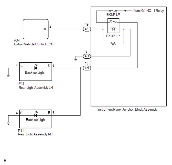
CAUTION / NOTICE / HINT

NOTICE:

  • Inspect the fuses for circuits related to this system before performing the following procedure.
  • Before replacing the hybrid vehicle control ECU, refer to Registration.

    Click here

PROCEDURE

1.

CHECK FOR DTC

(a) Connect the Techstream to the DLC3.

(b) Turn the power switch on (IG).

(c) Turn the Techstream on.

(d) Enter the following menus: Powertrain / Hybrid Control / Trouble Codes.

(e) Check for DTCs.

Powertrain > Hybrid Control > Trouble Codes

Result

Proceed to

Hybrid control system DTCs are not output

A

Hybrid control system DTCs are output

B

B

GO TO HYBRID CONTROL SYSTEM

A

2.

CHECK HARNESS AND CONNECTOR (INSTRUMENT PANEL JUNCTION BLOCK ASSEMBLY - BODY GROUND)

(a) Disconnect the 4D instrument panel junction block assembly connector.

(b) Measure the resistance according to the value(s) in the table below.

Standard Resistance:

Tester Connection

Condition

Specified Condition

4D-3 - Body ground

Always

Below 1 Ω

NG

REPAIR OR REPLACE HARNESS OR CONNECTOR

OK

3.

CHECK HARNESS AND CONNECTOR (HYBRID VEHICLE CONTROL ECU - INSTRUMENT PANEL JUNCTION BLOCK ASSEMBLY)

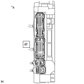
(a) Disconnect the 4F instrument panel junction block assembly connector.

(b) Disconnect the A24 hybrid vehicle control ECU connector.

(c) Measure the resistance according to the value(s) in the table below.

Standard Resistance:

Tester Connection

Condition

Specified Condition

A24-2 (BL) - 4F-19

Always

Below 1 Ω

A24-2 (BL) or 4F-19 - Body ground

Always

10 kΩ or higher

NG

REPAIR OR REPLACE HARNESS OR CONNECTOR

OK

4.

CHECK HYBRID VEHICLE CONTROL ECU (OUTPUT VOLTAGE)

*a

Component with harness connected

(Instrument Panel Junction Block Assembly)

(a) Connect the A24 hybrid vehicle control ECU connector.

(b) Connect the 4D and 4F instrument panel junction block assembly connectors.

(c) Measure the voltage according to the value(s) in the table below.

Standard Voltage:

Tester Connection

Condition

Specified Condition

4F-19 - Body ground

Power switch off, reverse (R) not selected

Below 1 V

4F-19 - Body ground

Power switch on (IG), reverse (R) selected

11 to 14 V

NG

REPLACE HYBRID VEHICLE CONTROL ECU

OK

5.

INSPECT INSTRUMENT PANEL JUNCTION BLOCK ASSEMBLY (OUTPUT VOLTAGE)

*a

Component with harness connected

(Instrument Panel Junction Block Assembly)

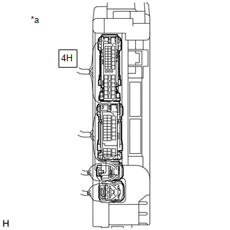
(a) Measure the voltage according to the value(s) in the table below.

Standard Voltage:

Tester Connection

Condition

Specified Condition

4H-10 - Body ground

Power switch off, reverse (R) not selected

Below 1 V

4H-10 - Body ground

Power switch on (IG), reverse (R) selected

11 to 14 V

OK

REPAIR OR REPLACE HARNESS OR CONNECTOR

NG

REPLACE INSTRUMENT PANEL JUNCTION BLOCK ASSEMBLY

    Light Sensor Circuit (B1244)

    Customize Parameters

    See More:

    Toyota Avalon (XX50) 2019-2022 Owners Manual > Do-it-yourself maintenance: Tire inflation pressure
    Tire inflation pressure The recommended cold tire inflation pressure and tire size are displayed on the tire and loading information label. Inspection and adjustment procedure Tire valve Tire pressure gauge 1. Remove the tire valve cap. 2. Press the tip of the tire pressure gauge onto the tire valve ...

    Toyota Avalon (XX50) 2019-2022 Owners Manual

    Toyota Avalon (XX50) 2019-2022 Service & Repair Manual

    © 2024 Copyright www.tavalon.net
    0.0403