COMPONENTS
ILLUSTRATION
|
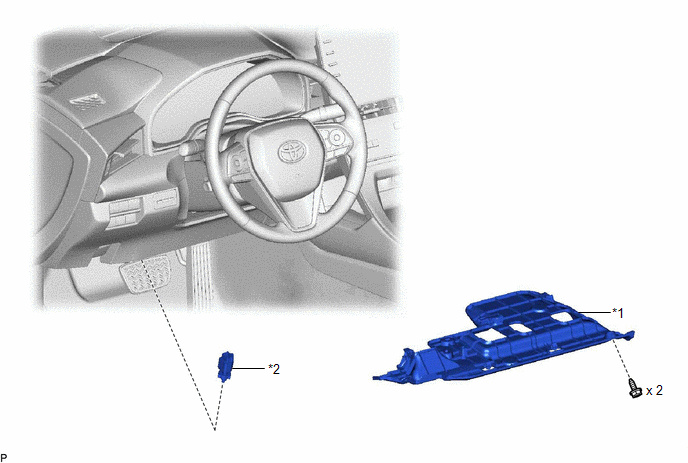
*1 | NO. 1 INSTRUMENT PANEL UNDER COVER SUB-ASSEMBLY |
*2 | STOP LIGHT SWITCH ASSEMBLY |
INSTALLATION
PROCEDURE
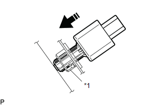
1. INSTALL STOP LIGHT SWITCH ASSEMBLY
(a) Insert the stop light switch assembly until the threaded sleeve hits the pedal as shown in the illustration.
|
*1 | Stop Light Switch Mounting Adjuster |
 |
Insert in this Direction |
NOTICE:
When inserting the stop light switch assembly, support the pedal from behind so that the pedal is not pushed in.
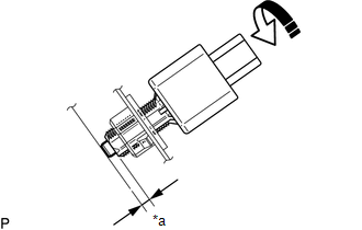
(b) Turn the stop light switch assembly 1/4 clockwise as shown in the illustration to install it.
|
*a | Protrusion of the Plunger |
|
|
Turn in this Direction |
Torque:
1.5 N·m {15 kgf·cm, 13 in·lbf}
or less
NOTICE:
When inserting the stop light switch assembly, support the pedal from behind so that the pedal is not pushed in.
(c) Connect the connector.
(d) Check the protrusion of the plunger.
Protrusion of the Plunger|
Area | Measurement |
|---|---|
|
a | 0.5 to 2.6 mm (0.0236 to 0.102 in.) |
(e) If the protrusion is not as specified, recheck the stop light switch assembly installation and perform brake pedal adjustment if necessary.
for Gasoline Model:
Click here 
for HV Model:
Click here
NOTICE:
Do not depress or support the brake pedal.
2. INSTALL NO. 1 INSTRUMENT PANEL UNDER COVER SUB-ASSEMBLY
Click here
ON-VEHICLE INSPECTION
PROCEDURE
1. INSPECT STOP LIGHT SWITCH ASSEMBLY
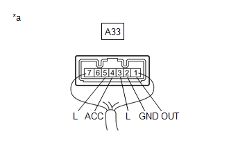
|
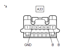
*a | Front view of wire harness connector (to Stop Light Switch Assembly) |
(a) Disconnect the A33 stop light switch assembly connector.
(b) Measure the voltage and resistance on the wire harness side connector according to the value(s) in the table below.
Standard Voltage:
|
Tester Connection | Condition |
Specified Condition |
|---|---|---|
|
A33-7 (B) - A33-2 (GND) |
Always | 11 to 14 V |
|
A33-6 (B) - A33-2 (GND) |
Power switch on (IG)*1 |
11 to 14 V |
|
Engine switch on (IG)*2 |
Standard Resistance:
|
Tester Connection | Condition |
Specified Condition |
|---|---|---|
|
A33-2 (GND) - Body ground |
Always | Below 1 Ω |
If the result is not as specified, repair or replace the wire harness or connector.
| (c) Connect the A33 stop light switch assembly connector. |
|
(d) Measure the voltage according to the value(s) in the table below.
Standard Voltage:
|
Tester Connection | Condition |
Specified Condition |
|---|---|---|
|
A33-1 (OUT) - A33-2 (GND) |
Power switch off, brake pedal not depressed*1 |
Below 1 V |
|
Engine switch off, brake pedal not depressed*2 | ||
|
A33-1 (OUT) - A33-2 (GND) |
Power switch off, brake pedal depressed*1 |
11 to 14 V |
|
Engine switch off, brake pedal depressed*2 | ||
|
A33-3 (L) - A33-2 (GND) |
Power switch off, brake pedal not depressed*1 |
Below 1 V |
|
Engine switch off, brake pedal not depressed*2 | ||
|
A33-3 (L) - A33-2 (GND) |
Power switch off, brake pedal depressed*1 |
11 to 14 V |
|
Engine switch off, brake pedal depressed*2 | ||
|
A33-4 (ACC) - A33-2 (GND) |
Always | 11 to 14 V |
|
A33-5 (L) - A33-2 (GND) |
Power switch on (IG), brake pedal not depressed*1 |
11 to 14 V |
|
Engine switch on (IG), brake pedal not depressed*2 | ||
|
A33-5 (L) - A33-2 (GND) |
Power switch on (IG), brake pedal depressed*1 |
Below 1 V |
|
Engine switch on (IG), brake pedal depressed*2 |
If the result is not as specified, replace the stop light switch assembly.
REMOVAL
PROCEDURE
1. REMOVE NO. 1 INSTRUMENT PANEL UNDER COVER SUB-ASSEMBLY
Click here 
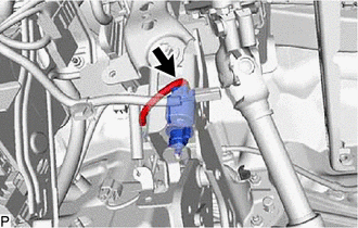
2. REMOVE STOP LIGHT SWITCH ASSEMBLY
| (a) Disconnect the connector. |
|
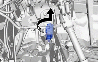
(b) Turn the stop light switch assembly counterclockwise as shown in the illustration and remove it.
 |
Remove in this Direction |
Toyota Avalon (XX50) 2019-2022 Service & Repair Manual > Exterior Panels / Trim: Roof Drip Side Finish Moulding
ComponentsCOMPONENTS ILLUSTRATION *1 CENTER ROOF DRIP SIDE FINISH MOULDING *2 NO. 1 ROOF DRIP SIDE FINISH MOULDING CLIP ● Non-reusable part - - InstallationINSTALLATION CAUTION / NOTICE / HINT HINT: Use the same procedure for the RH side and LH side. The following procedure is for the LH side. PR ...