Toyota Avalon Service & Repair Manual: Mirror Heater does not Operate with Rear Defogger Switch

DESCRIPTION

When the mirror heater switch (rear window defogger switch) on the radio and display receiver assembly is pressed, the operation signal is sent to the air conditioning amplifier assembly via CAN communication. When the air conditioning amplifier assembly receives the signal, it turns on the DEF relay to operate the mirror heaters.

WIRING DIAGRAM

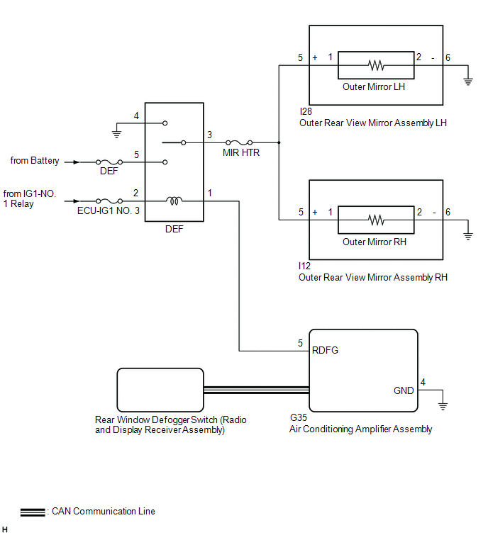
CAUTION / NOTICE / HINT

NOTICE:

  • The power mirror control system (for Gasoline Model without Memory) uses the CAN communication system. Inspect the communication functions by following How to Proceed with Troubleshooting. Troubleshoot the power mirror control system (for Gasoline Model without Memory) after confirming that the communication systems are functioning properly.
  • Inspect the fuses for circuits related to this system before performing the following procedure.
  • If the battery voltage is low, the mirror heater function may not operate.

PROCEDURE

1.

PERFORM ACTIVE TEST USING TECHSTREAM

(a) Connect the Techstream to the DLC3.

(b) Turn the engine switch on (IG).

(c) Turn the Techstream on.

(d) Enter the following menus: Body Electrical / Air Conditioner / Active Test.

(e) Perform the Active Test according to the display on the Techstream.

Body Electrical > Air Conditioner > Active Test

Tester Display

Measurement Item

Control Range

Diagnostic Note

Defogger Relay (Rear)

Mirror Heater

OFF or ON

-

Body Electrical > Air Conditioner > Active Test

Tester Display

Defogger Relay (Rear)

Result

Proceed to

Mirror heater operation on both mirrors is not normal

A

Mirror heater operation on RH side mirror is not normal

B

Mirror heater operation on LH side mirror is not normal

C

B

GO TO STEP 4

C

GO TO STEP 6

A

2.

CHECK WINDOW DEFOGGER SYSTEM

(a) Check the window defogger system operation.

Click here

OK:

The window defogger system operates normally.

NG

GO TO WINDOW DEFOGGER SYSTEM

OK

3.

CHECK HARNESS AND CONNECTOR (DEF RELAY - OUTER REAR VIEW MIRROR ASSEMBLY RH/LH - BODY GROUND)

(a) Remove the DEF relay from the No. 1 engine room relay block and No. 1 junction block assembly.

(b) Disconnect the I12 outer rear view mirror assembly RH connector.

(c) Disconnect the I28 outer rear view mirror assembly LH connector.

(d) Measure the resistance according to the value(s) in the table below.

Standard Resistance:

Tester Connection

Condition

Specified Condition

DEF relay holder terminal 3 - I28-5 (+)

Always

Below 1 Ω

DEF relay holder terminal 3 - I12-5 (+)

Always

Below 1 Ω

DEF relay holder terminal 3 - Body ground

Always

10 kΩ or higher

OK

USE SIMULATION METHOD TO CHECK

NG

REPAIR OR REPLACE HARNESS OR CONNECTOR

4.

CHECK HARNESS AND CONNECTOR (DEF RELAY - OUTER REAR VIEW MIRROR ASSEMBLY RH - BODY GROUND)

(a) Remove the DEF relay from the No. 1 engine room relay block and No. 1 junction block assembly.

(b) Disconnect the I12 outer rear view mirror assembly RH connector.

(c) Disconnect the I28 outer rear view mirror assembly LH connector.

(d) Measure the resistance according to the value(s) in the table below.

Standard Resistance:

Tester Connection

Condition

Specified Condition

DEF relay holder terminal 3 - I12-5 (+)

Always

Below 1 Ω

I12-6 (-) - Body ground

Always

Below 1 Ω

I12-5 (+) or DEF relay holder terminal 3 - Body ground

Always

10 kΩ or higher

NG

REPAIR OR REPLACE HARNESS OR CONNECTOR

OK

5.

INSPECT OUTER MIRROR RH

(a) Remove the outer mirror RH.

Click here

(b) Inspect the outer mirror RH.

Click here

OK:

Outer mirror RH is normal.

OK

REPLACE OUTER REAR VIEW MIRROR ASSEMBLY RH

NG

REPLACE OUTER MIRROR RH

6.

CHECK HARNESS AND CONNECTOR (DEF RELAY - OUTER REAR VIEW MIRROR ASSEMBLY LH - BODY GROUND)

(a) Remove the DEF relay from the No. 1 engine room relay block and No. 1 junction block assembly.

(b) Disconnect the I28 outer rear view mirror assembly LH connector.

(c) Disconnect the I12 outer rear view mirror assembly RH connector.

(d) Measure the resistance according to the value(s) in the table below.

Standard Resistance:

Tester Connection

Condition

Specified Condition

DEF relay holder terminal 3 - I28-5 (+)

Always

Below 1 Ω

I28-6 (-) - Body ground

Always

Below 1 Ω

I28-5 (+) or DEF relay holder terminal 3 - Body ground

Always

10 kΩ or higher

NG

REPAIR OR REPLACE HARNESS OR CONNECTOR

OK

7.

INSPECT OUTER MIRROR LH

(a) Remove the outer mirror LH.

Click here

(b) Inspect the outer mirror LH.

Click here

OK:

Outer mirror LH is normal.

OK

REPLACE OUTER REAR VIEW MIRROR ASSEMBLY LH

NG

REPLACE OUTER MIRROR LH

    How To Proceed With Troubleshooting

    Operation Check

    See More:

    Toyota Avalon Service & Repair Manual > Dynamic Radar Cruise Control System(for Hv Model): Definition Of Terms
    DEFINITION OF TERMS Term Definition Monitor description Description of what the hybrid vehicle control ECU monitors and how it detects malfunctions (monitoring purpose and details). Related DTCs Group of diagnostic trouble codes that are output by the hybrid vehicle control ECU based on the same mal ...

    Toyota Avalon Owners Manual

    Toyota Avalon Service & Repair Manual

    © 2024 Copyright www.tavalon.net
    0.0148