DATA LIST / ACTIVE TEST
ACTIVE TEST
HINT:
Using the Techstream to perform Active Tests allows relays, VSVs, actuators and other items to be operated without removing any parts. This non-intrusive functional inspection can be very useful because intermittent operation may be discovered before parts or wiring is disturbed. Performing Active Tests early in troubleshooting is one way to save diagnostic time. Data List information can be displayed while performing Active Tests.
(a) Connect the Techstream to the DLC3.
(b) Turn the engine switch on (IG).
(c) Turn the Techstream on.
(d) Enter the following menus: Body Electrical / Air Conditioner / Active Test.
(e) Perform the Active Test according to the display on the Techstream.
Body Electrical > Air Conditioner > Active Test|
Tester Display | Measurement Item |
Control Range | Diagnostic Note |
|---|---|---|---|
|
Defogger Relay (Rear) |
Mirror Heater | OFF or ON |
- |
DIAGNOSIS SYSTEM
CHECK DLC3
(a) Check the DLC3.
Click here 
INSPECT BATTERY VOLTAGE
(a) Measure the battery voltage.
Standard Voltage:
11 to 14 V
If the voltage is below 11 V, recharge or replace the battery.
CAUTION / NOTICE / HINT
HINT:
PROCEDURE
|
1. | VEHICLE BROUGHT TO WORKSHOP |
|
| 2. |
CUSTOMER PROBLEM ANALYSIS |
HINT:
|
What |
Vehicle model, system name |
|
When |
Date, time, occurrence frequency |
|
Where |
Road conditions |
|
Under what conditions? |
Driving conditions, weather conditions |
|
How did it happen? |
Problem symptoms |
|
| 3. |
PRE-CHECK |
(a) Measure the battery voltage.
Standard Voltage:
11 to 14 V
If the voltage is below 11 V, recharge or replace the battery before proceeding to the next step.
(b) Check the fuses and relays.
(c) Check the connector connections and terminals to make sure that there are no abnormalities such as loose connections, deformation, etc.
|
| 4. |
CHECK COMMUNICATION FUNCTION OF CAN COMMUNICATION SYSTEM* |
(a) Using the Techstream, check for CAN communication system DTCs.
Click here

|
Result | Proceed to |
|---|---|
|
CAN DTCs are not output |
A |
| CAN DTCs are output |
B |
| B |
 | GO TO CAN COMMUNICATION SYSTEM |
|
| 5. |
PROBLEM SYMPTOMS TABLE |
(a) Refer to Problem Symptoms Table.
Click here
|
Result | Proceed to |
|---|---|
|
Fault is not listed in Problem Symptoms Table |
A |
| Fault is listed in Problem Symptoms Table |
B |
| B |
| GO TO STEP 7 |
|
| 6. |
OVERALL ANALYSIS AND TROUBLESHOOTING* |
(a) Operation Check
Click here
(b) Terminals of ECU
Click here
(c) Data List / Active Test
Click here
(d) Inspection
|
| 7. |
REPAIR OR REPLACE |
|
| 8. |
CONFIRMATION TEST |
| NEXT | | END |
DESCRIPTION
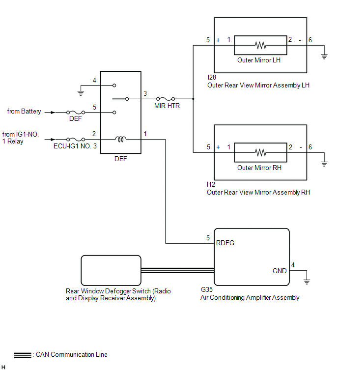
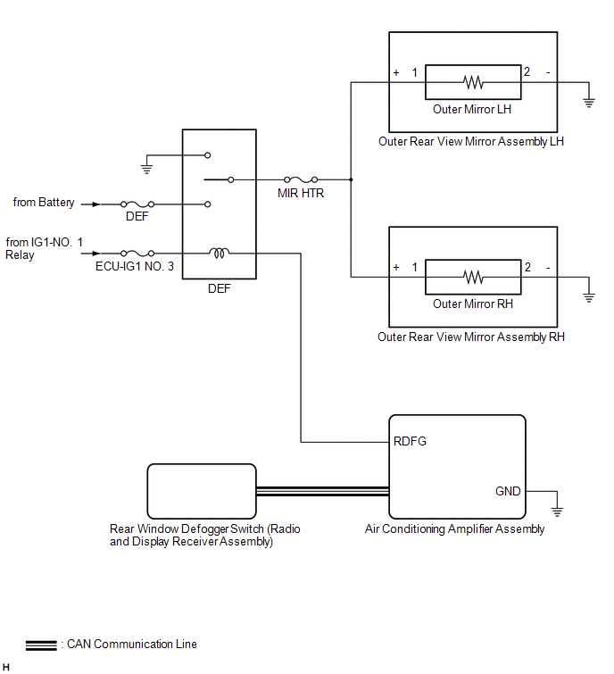
When the mirror heater switch (rear window defogger switch) on the radio and display receiver assembly is pressed, the operation signal is sent to the air conditioning amplifier assembly via CAN communication. When the air conditioning amplifier assembly receives the signal, it turns on the DEF relay to operate the mirror heaters.
WIRING DIAGRAM
CAUTION / NOTICE / HINT
NOTICE:
PROCEDURE
|
1. | PERFORM ACTIVE TEST USING TECHSTREAM |
(a) Connect the Techstream to the DLC3.
(b) Turn the engine switch on (IG).
(c) Turn the Techstream on.
(d) Enter the following menus: Body Electrical / Air Conditioner / Active Test.
(e) Perform the Active Test according to the display on the Techstream.
Body Electrical > Air Conditioner > Active Test|
Tester Display | Measurement Item |
Control Range | Diagnostic Note |
|---|---|---|---|
|
Defogger Relay (Rear) |
Mirror Heater | OFF or ON |
- |
|
Tester Display |
|---|
| Defogger Relay (Rear) |
|
Result | Proceed to |
|---|---|
|
Mirror heater operation on both mirrors is not normal |
A |
| Mirror heater operation on RH side mirror is not normal |
B |
| Mirror heater operation on LH side mirror is not normal |
C |
| B |
 | GO TO STEP 4 |
| C |
| GO TO STEP 6 |
|
| 2. |
CHECK WINDOW DEFOGGER SYSTEM |
(a) Check the window defogger system operation.
Click here 
OK:
The window defogger system operates normally.
| NG | | GO TO WINDOW DEFOGGER SYSTEM |
|
| 3. |
CHECK HARNESS AND CONNECTOR (DEF RELAY - OUTER REAR VIEW MIRROR ASSEMBLY RH/LH - BODY GROUND) |
(a) Remove the DEF relay from the No. 1 engine room relay block and No. 1 junction block assembly.
(b) Disconnect the I12 outer rear view mirror assembly RH connector.
(c) Disconnect the I28 outer rear view mirror assembly LH connector.
(d) Measure the resistance according to the value(s) in the table below.
Standard Resistance:
|
Tester Connection | Condition |
Specified Condition |
|---|---|---|
|
DEF relay holder terminal 3 - I28-5 (+) |
Always | Below 1 Ω |
|
DEF relay holder terminal 3 - I12-5 (+) |
Always | Below 1 Ω |
|
DEF relay holder terminal 3 - Body ground |
Always | 10 kΩ or higher |
| OK | | USE SIMULATION METHOD TO CHECK |
| NG | | REPAIR OR REPLACE HARNESS OR CONNECTOR |
| 4. |
CHECK HARNESS AND CONNECTOR (DEF RELAY - OUTER REAR VIEW MIRROR ASSEMBLY RH - BODY GROUND) |
(a) Remove the DEF relay from the No. 1 engine room relay block and No. 1 junction block assembly.
(b) Disconnect the I12 outer rear view mirror assembly RH connector.
(c) Disconnect the I28 outer rear view mirror assembly LH connector.
(d) Measure the resistance according to the value(s) in the table below.
Standard Resistance:
|
Tester Connection | Condition |
Specified Condition |
|---|---|---|
|
DEF relay holder terminal 3 - I12-5 (+) |
Always | Below 1 Ω |
|
I12-6 (-) - Body ground |
Always | Below 1 Ω |
|
I12-5 (+) or DEF relay holder terminal 3 - Body ground |
Always | 10 kΩ or higher |
| NG | | REPAIR OR REPLACE HARNESS OR CONNECTOR |
|
| 5. |
INSPECT OUTER MIRROR RH |
(a) Remove the outer mirror RH.
Click here
(b) Inspect the outer mirror RH.
Click here
OK:
Outer mirror RH is normal.
| OK | | REPLACE OUTER REAR VIEW MIRROR ASSEMBLY RH |
| NG | | REPLACE OUTER MIRROR RH |
| 6. |
CHECK HARNESS AND CONNECTOR (DEF RELAY - OUTER REAR VIEW MIRROR ASSEMBLY LH - BODY GROUND) |
(a) Remove the DEF relay from the No. 1 engine room relay block and No. 1 junction block assembly.
(b) Disconnect the I28 outer rear view mirror assembly LH connector.
(c) Disconnect the I12 outer rear view mirror assembly RH connector.
(d) Measure the resistance according to the value(s) in the table below.
Standard Resistance:
|
Tester Connection | Condition |
Specified Condition |
|---|---|---|
|
DEF relay holder terminal 3 - I28-5 (+) |
Always | Below 1 Ω |
|
I28-6 (-) - Body ground |
Always | Below 1 Ω |
|
I28-5 (+) or DEF relay holder terminal 3 - Body ground |
Always | 10 kΩ or higher |
| NG | | REPAIR OR REPLACE HARNESS OR CONNECTOR |
|
| 7. |
INSPECT OUTER MIRROR LH |
(a) Remove the outer mirror LH.
Click here
(b) Inspect the outer mirror LH.
Click here
OK:
Outer mirror LH is normal.
| OK | | REPLACE OUTER REAR VIEW MIRROR ASSEMBLY LH |
| NG | | REPLACE OUTER MIRROR LH |
OPERATION CHECK
CHECK ELECTRICAL REMOTE CONTROL MIRROR FUNCTION
(a) Turn the engine switch on (IG).
(b) With L on the mirror select switch selected, check that the outer rear view mirror assembly LH surface moves up, down, left and right normally.
(c) With R on the mirror select switch selected, check that the outer rear view mirror assembly RH surface moves up, down, left and right normally.
CHECK MIRROR HEATER FUNCTION
(a) Turn the engine switch on (IG).
(b) Check that pressing the mirror heater switch (rear window defogger switch) illuminates the indicator and warms the mirror surfaces.
(c) Check that after approximately 15 minutes, the indicator light turns off and the mirror heaters deactivate.
HINT:
There is a timer extension function which can operate the mirror heaters for up to an additional 45 minutes.
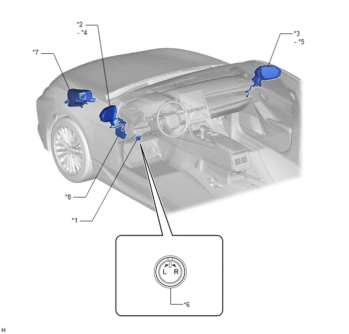
PARTS LOCATION
ILLUSTRATION
|
*1 | OUTER MIRROR SWITCH ASSEMBLY |
*2 | OUTER REAR VIEW MIRROR ASSEMBLY LH |
|
*3 | OUTER REAR VIEW MIRROR ASSEMBLY RH |
*4 | OUTER MIRROR LH |
|
*5 | OUTER MIRROR RH |
*6 | MIRROR SELECT AND SURFACE ADJUST SWITCH |
|
*7 | NO. 1 ENGINE ROOM RELAY BLOCK AND NO. 1 JUNCTION BLOCK ASSEMBLY - DEF FUSE - DEF RELAY - MIR HTR FUSE |
*8 | INSTRUMENT PANEL JUNCTION BLOCK ASSEMBLY - ECU-ACC FUSE - ECU-IG1 NO. 3 FUSE |
ILLUSTRATION
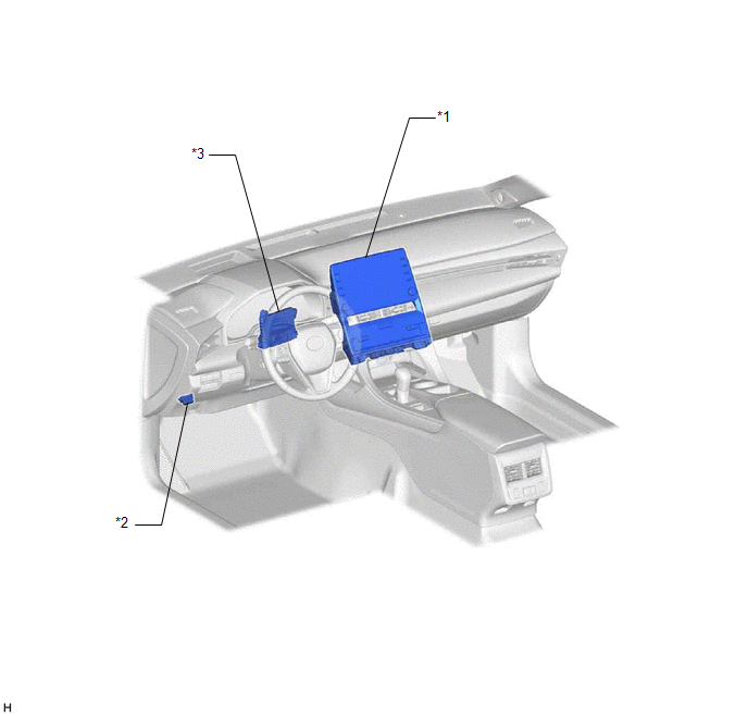
|
*1 | REAR WINDOW DEFOGGER SWITCH (RADIO AND DISPLAY RECEIVER ASSEMBLY) |
*2 | DLC3 |
|
*3 | AIR CONDITIONING AMPLIFIER ASSEMBLY |
- | - |
PRECAUTION
PRECAUTION FOR DISCONNECTING CABLE FROM NEGATIVE BATTERY TERMINAL
NOTICE:
When disconnecting the cable from the negative (-) battery terminal, initialize the following systems after the cable is reconnected.
|
System Name | See Procedure |
|---|---|
|
Lane Departure Alert System (w/ Steering Control) |
|
|
Intelligent Clearance Sonar System | |
|
Parking Assist Monitor System | |
|
Panoramic View Monitor System | |
|
Pre-collision System | |
|
Lighting System (for Gasoline Model with Cornering Light) |
PROBLEM SYMPTOMS TABLE
NOTICE:
If the battery voltage is low, the mirror heater function may not operate.
HINT:
|
Symptom | Suspected Area |
Link |
|---|---|---|
|
Electrical remote control mirror does not operate |
Outer mirror switch assembly |
|
|
Outer rear view mirror assembly LH |
| |
|
Outer rear view mirror assembly RH |
| |
|
Wire harness or connector |
- | |
| Mirror heater does not operate |
Proceed to "Mirror Heater does not Operate with Rear Defogger Switch" |
|
SYSTEM DESCRIPTION
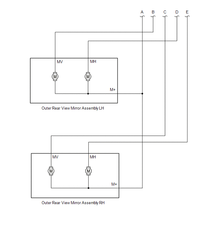
POWER MIRROR CONTROL SYSTEM (for Gasoline Model without Memory) DESCRIPTION
(a) This system has the following functions: electrical remote control mirror function and mirror heater function.
FUNCTION OF MAIN COMPONENT
|
Component | Function | |
|---|---|---|
|
Outer rear view mirror assembly |
Vertical mirror motor | Receives signals from the outer mirror switch assembly and adjusts the mirror surface position vertically. |
|
Horizontal mirror motor | Receives signals from the outer mirror switch assembly and adjusts the mirror surface position horizontally. | |
|
Mirror heater | When the mirror heater switch (rear window defogger switch) on the radio and display receiver assembly is operated, the air conditioning amplifier assembly detects the switch operation via CAN communication. The air conditioning amplifier assembly operates DEF relay and mirror heaters in accordance with the switch operation. | |
|
Outer mirror switch assembly |
Mirror select switch | Consists of individual R and L switches. One must be selected to operate the mirror adjust switch. |
|
Mirror adjust switch | After selecting the R or L switch, the right, left, up and down control switches can be operated to change the angle of the mirror surface. | |
SYSTEM OPERATION
(a) The power mirror control system (for Gasoline Model without Memory) has the following features:
|
Function | Outline |
|---|---|
|
Electrical remote control mirror function |
When the outer mirror switch assembly is operated, this function moves the mirror surface vertically or horizontally to enable the driver to attain an optimal mirror angle. Turning the mirror select switch to the R position operates the right side mirror, and turning the mirror select switch to the L position operates the left side mirror. |
|
Mirror heater function | Turns on the mirror heaters when the rear window defogger is turned on. The rear window defogger and mirror heaters automatically turn off 15 minutes after the rear window defogger and mirror heaters were activated. The rear window defogger and mirror heaters continue to operate up to an additional 45 minutes if the following conditions are met.
|
SYSTEM DIAGRAM
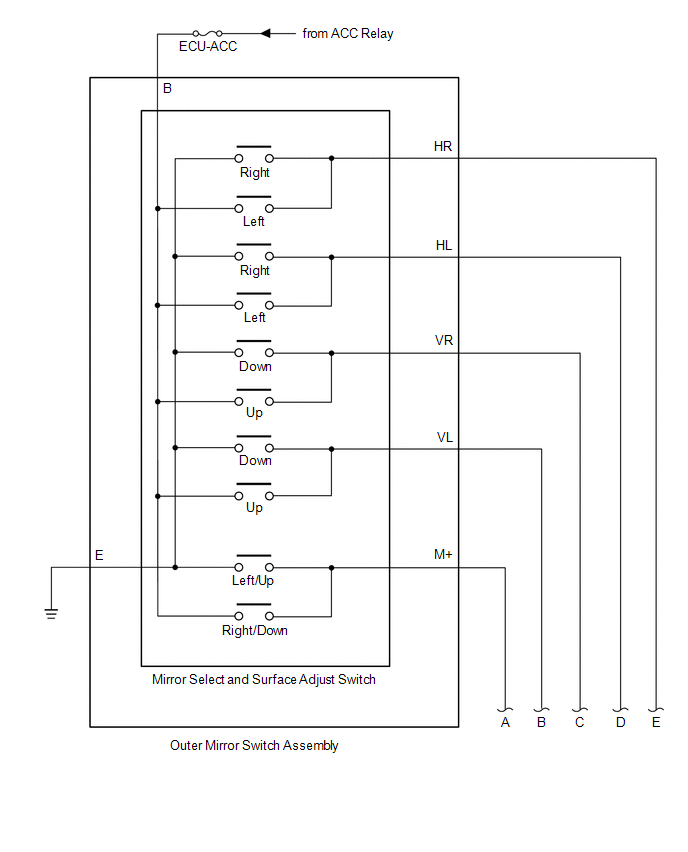
ELECTRICAL REMOTE CONTROL MIRROR FUNCTION
MIRROR HEATER FUNCTION
 Communication Table
 |
Sender | Receiver |
Signal | Communication Method |
|---|---|---|---|
|
Radio and Display Receiver Assembly |
Air Conditioning Amplifier Assembly |
Mirror heater switch (rear window defogger switch) signal |
CAN |
TERMINALS OF ECU
CHECK AIR CONDITIONING AMPLIFIER ASSEMBLY
Click here 
RADIO AND DISPLAY RECEIVER ASSEMBLY
Click here
Toyota Avalon (XX50) 2019-2022 Service & Repair Manual > Hybrid Control System: Transmission (Input) Mechanical Linkage Failure (P1C8679). Generator Mechanical Linkage Failure (P1C8779,P1C8879). Hybrid/EV Battery Block 1 Voltage Difference Out of Range (P1CBE1E,P1CBF1E,P1CC01E-P1
Transmission (Input) Mechanical Linkage Failure (P1C8679) DTC SUMMARY Refer to the DTC summary for DTC P1C7779. Click here DESCRIPTION Refer to the description for DTC P1C7779. Click here DTC No. Detection Item DTC Detection Condition Trouble Area MIL Warning Indicate P1C8679 Transmission (Input) Me ...


