DESCRIPTION If any of the M1 or M2 seat memory switch is pressed, the outer mirror control ECU assembly LH detects the switch operation and sends the seat memory switch signal to the main body ECU (multiplex network body ECU) via CAN communication. On receiving the seat memory switch signal, the main body ECU (multiplex network body ECU) sends the memory request signal to each outer mirror control ECU assembly via CAN communication. When receiving this signal, each outer mirror control ECU assembly stores the mirror surface position based on information from the mirror position sensor, which is built into the outer rear view mirror assembly. WIRING DIAGRAM 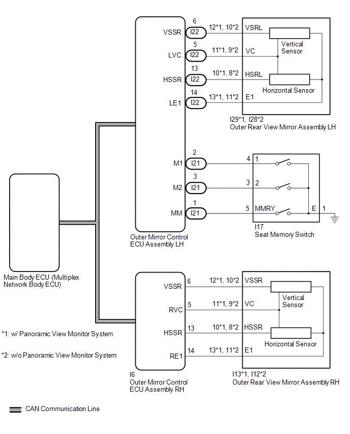 CAUTION / NOTICE / HINT NOTICE:
HINT: Each outer rear view mirror assembly has a built-in mirror vertical position sensor and mirror horizontal position sensor. PROCEDURE
(a) Connect the Techstream to the DLC3. (b) Turn the power switch on (IG). (c) Turn the Techstream on. (d) Enter the following menus: Body Electrical / Mirror L or Mirror R / Data List. (e) Read the Data List according to the display on the Techstream. Body Electrical > Mirror L > Data List
OK: On the Techstream screen, ON or OFF is displayed accordingly.
(a) When any seat memory switch (M1 or M2) is pressed, check that the driver seat moves to the memorized position. Click here OK: The driver seat moves to the memorized position.
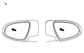
(b) Using the outer mirror switch assembly, turn the mirror surface to the fully left position. (c) Press the M1 switch while the SET switch is being pressed. (d) Check that the buzzer sounds for 0.5 seconds and the mirror surface position is memorized. (e) Using the outer mirror switch assembly, turn the mirror surface to the fully right position. (f) Press the M1 switch. (g) Check that the buzzer sounds for 0.1 seconds and the outer mirror automatically moves to the memorized fully left position.
(a) Temporarily replace the outer rear view mirror assembly LH with a new or known good one. Click here
(b) Using the outer mirror switch assembly, turn the mirror surface to the fully left position. (c) Press the M1 switch while the SET switch is being pressed. (d) Check that the buzzer sounds for 0.5 seconds and the mirror surface position is memorized. (e) Using the outer mirror switch assembly, turn the mirror surface to the fully right position. (f) Press the M1 switch. (g) Check that the buzzer sounds for 0.1 seconds and the outer mirror automatically moves to the memorized fully left position.
(a) Temporarily replace the outer rear view mirror assembly RH with a new or known good one. Click here
(b) Using the outer mirror switch assembly, turn the mirror surface to the fully left position. (c) Press the M1 switch while the SET switch is being pressed. (d) Check that the buzzer sounds for 0.5 seconds and the mirror surface position is memorized. (e) Using the outer mirror switch assembly, turn the mirror surface to the fully right position. (f) Press the M1 switch. (g) Check that the buzzer sounds for 0.1 seconds and the outer mirror automatically moves to the memorized fully left position.
(a) Remove the seat memory switch. Click here (b) Inspect the seat memory switch. Click here
(a) Disconnect the I21 outer mirror control ECU assembly LH connector. (b) Disconnect the I17 seat memory switch connector. (c) Measure the resistance according to the value(s) in the table below. Standard Resistance:
|
Toyota Avalon (XX50) 2019-2022 Service & Repair Manual > Engine Coolant Temperature Sensor: Inspection
INSPECTION PROCEDURE 1. INSPECT ENGINE COOLANT TEMPERATURE SENSOR CAUTION: Do not put your hands into the water that has been heated for the inspection. Touching the heated water could result in burns. (a) Measure the resistance according to the value(s) in the table below. Standard Resistance: Test ...