DESCRIPTION
When the sliding roof ECU (sliding roof drive gear assembly) detects a motor malfunction and the sliding roof operation is stopped, DTC B2341 is stored.
When the sliding roof ECU (sliding roof drive gear assembly) detects a gear position malfunction and the sliding roof operation is stopped, DTC B2344 is stored.
|
DTC No. | Detection Item |
DTC Detection Condition | Trouble Area |
|---|---|---|---|
|
B2341 | Sensor (Motor) Failure |
Sensor (motor) failure (The sliding roof ECU (sliding roof drive gear assembly) enters fail-safe mode due to a problem with the motor) |
|
| B2344 |
Position Failure | Position failure (The sliding roof ECU (sliding roof drive gear assembly) enters fail-safe mode due to a problem with the gear position) |
|
WIRING DIAGRAM
CAUTION / NOTICE / HINT
NOTICE:
If the sliding roof ECU (sliding roof drive gear assembly) is removed and reinstalled or replaced, the sliding roof ECU (sliding roof drive gear assembly) must be initialized.
Click here 
PROCEDURE
| 1. |
CHECK SLIDING ROOF OPERATION |
(a) Check the sliding roof auto operation.
Click here
OK:
Auto operation operates normally.
| NG |  | GO TO STEP 3 |
|
| 2. |
CHECK DTC OUTPUT |
(a) Clear the DTCs.
Body Electrical > Sliding Roof > Clear DTCs(b) Check for DTCs.
Body Electrical > Sliding Roof > Trouble CodesOK:
DTCs B2341 and B2344 are not output.
| OK | | USE SIMULATION METHOD TO CHECK |
| NG | | REPLACE SLIDING ROOF ECU (SLIDING ROOF DRIVE GEAR ASSEMBLY) |
| 3. |
INITIALIZE SLIDING ROOF ECU (SLIDING ROOF DRIVE GEAR ASSEMBLY) |
(a) Check that the sliding roof ECU (sliding roof drive gear assembly) can be initialized.
Click here
OK:
Sliding roof ECU (sliding roof drive gear assembly) can be initialized.
| NG | | GO TO STEP 5 |
|
| 4. |
CHECK DTC OUTPUT |
(a) Clear the DTCs.
Body Electrical > Sliding Roof > Clear DTCs(b) Check for DTCs.
Body Electrical > Sliding Roof > Trouble CodesOK:
DTCs B2341 and B2344 are not output.
| OK | | END (MALFUNCTION DUE TO INITIALIZATION FAILURE) |
| NG | | REPLACE SLIDING ROOF ECU (SLIDING ROOF DRIVE GEAR ASSEMBLY) |
| 5. |
CHECK HARNESS AND CONNECTOR (SLIDING ROOF ECU (SLIDING ROOF DRIVE GEAR ASSEMBLY) - SLIDING ROOF SWITCH (ROOF CONSOLE BOX SUB-ASSEMBLY) AND BODY GROUND) |
(a) Disconnect the O10 sliding roof switch (roof console box sub-assembly) connector.
(b) Disconnect the O3 sliding roof ECU (sliding roof drive gear assembly) connector.
(c) Measure the resistance according to the value(s) in the table below.
Standard Resistance:
|
Tester Connection | Condition |
Specified Condition |
|---|---|---|
|
O3-8 (CLS) - O10-4 (CLS) |
Always | Below 1 Ω |
|
O3-8 (CLS) or O10-4 (CLS) - Body ground |
Always | 10 kΩ or higher |
|
O3-10 (OPN) - O10-5 (OPN) |
Always | Below 1 Ω |
|
O3-10 (OPN) or O10-5 (OPN) - Body ground |
Always | 10 kΩ or higher |
|
O3-9 (DWN) - O10-18 (DOWN) |
Always | Below 1 Ω |
|
O3-9 (DWN) or O10-18 (DOWN) - Body ground |
Always | 10 kΩ or higher |
|
O3-5 (UP) - O10-3 (UP) |
Always | Below 1 Ω |
|
O3-5 (UP) or O10-3 (UP) - Body ground |
Always | 10 kΩ or higher |
|
O10-15 (GND) - Body ground |
Always | Below 1 Ω |
|
O3-2 (E) - Body ground |
Always | Below 1 Ω |
| NG | | REPAIR OR REPLACE HARNESS OR CONNECTOR |
|
| 6. |
INSPECT SLIDING ROOF SWITCH (ROOF CONSOLE BOX SUB-ASSEMBLY) |
(a) Remove the sliding roof switch (roof console box sub-assembly).
Click here
(b) Inspect the sliding roof switch (roof console box sub-assembly).
Click here
| OK | | REPLACE SLIDING ROOF ECU (SLIDING ROOF DRIVE GEAR ASSEMBLY) |
| NG | | REPLACE SLIDING ROOF SWITCH (ROOF CONSOLE BOX SUB-ASSEMBLY) |
DESCRIPTION
This DTC is stored when the sliding roof ECU (sliding roof drive gear assembly) detects that the sliding roof switch (roof console box sub-assembly) is stuck for 30 seconds or more.
|
DTC No. | Detection Item |
DTC Detection Condition | Trouble Area |
|---|---|---|---|
|
B2342 | Switch Failure |
Sliding roof ECU (sliding roof drive gear assembly) detects sliding roof switch (roof console box sub-assembly) is stuck for 30 seconds or more |
|
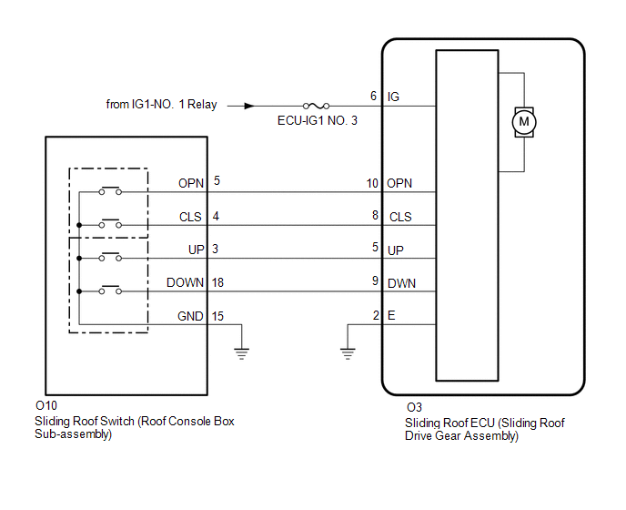
WIRING DIAGRAM
Refer to DTC B2341.
Click here 
CAUTION / NOTICE / HINT
NOTICE:
If the sliding roof ECU (sliding roof drive gear assembly) is removed and reinstalled or replaced, the sliding roof ECU (sliding roof drive gear assembly) must be initialized.
Click here
PROCEDURE
| 1. |
READ VALUE USING TECHSTREAM |
(a) Connect the Techstream to the DLC3.
(b) Turn the power switch on (IG).
(c) Turn the Techstream on.
(d) Enter the following menus: Body Electrical / Sliding Roof / Data List.
(e) Read the Data List according to the display on the Techstream.
Body Electrical > Sliding Roof > Data List|
Tester Display | Measurement Item |
Range | Normal Condition |
Diagnostic Note |
|---|---|---|---|---|
|
Open Switch Failure(Past) |
Open switch failure signal (Past) |
OFF or ON | OFF: No sliding roof open switch failure signal (Past) ON: Sliding roof open switch failure signal (Past) |
- |
| Close Switch Failure(Past) |
Close switch failure signal (Past) |
OFF or ON | OFF: No sliding roof close switch failure signal (Past) ON: Sliding roof close switch failure signal (Past) |
- |
| Up Switch Failure(Past) |
Up switch failure signal (Past) |
OFF or ON | OFF: No sliding roof tilt up switch failure signal (Past) ON: Sliding roof tilt up switch failure signal (Past) |
- |
| Down Switch Failure(Past) |
Down switch failure signal (Past) |
OFF or ON | OFF: No sliding roof tilt down switch failure signal (Past) ON: Sliding roof tilt down switch failure signal (Past) |
- |
| Open Switch Failure(Current) |
Open switch failure signal (Current) |
OFF or ON | OFF: No sliding roof open switch failure signal (Current) ON: Sliding roof open switch failure signal (Current) |
- |
| Close Switch Failure(Current) |
Close switch failure signal (Current) |
OFF or ON | OFF: No sliding roof close switch failure signal (Current) ON: Sliding roof close switch failure signal (Current) |
- |
| Up Switch Failure(Current) |
Up switch failure signal (Current) |
OFF or ON | OFF: No sliding roof tilt up switch failure signal (Current) ON: Sliding roof tilt up switch failure signal (Current) |
- |
| Down Switch Failure(Current) |
Down switch failure signal (Current) |
OFF or ON | OFF: No sliding roof tilt down switch failure signal (Current) ON: Sliding roof tilt down switch failure signal (Current) |
- |
|
Tester Display |
|---|
| Open Switch Failure(Past) |
|
Close Switch Failure(Past) |
|
Up Switch Failure(Past) |
|
Down Switch Failure(Past) |
|
Open Switch Failure(Current) |
|
Close Switch Failure(Current) |
|
Up Switch Failure(Current) |
|
Down Switch Failure(Current) |
OK:
OFF is displayed for each Data List item.
| OK |  | REPLACE SLIDING ROOF ECU (SLIDING ROOF DRIVE GEAR ASSEMBLY) |
|
| 2. |
CHECK HARNESS AND CONNECTOR (SLIDING ROOF ECU (SLIDING ROOF DRIVE GEAR ASSEMBLY) - BODY GROUND) |
(a) Disconnect the O3 sliding roof ECU (sliding roof drive gear assembly) connector.
(b) Disconnect the O10 sliding roof switch (roof console box sub-assembly) connector.
(c) Measure the resistance according to the value(s) in the table below.
Standard Resistance:
|
Tester Connection | Condition |
Specified Condition |
|---|---|---|
|
O3-10 (OPN) - Body ground |
Always | 10 kΩ or higher |
|
O3-8 (CLS) - Body ground |
Always | 10 kΩ or higher |
|
O3-5 (UP) - Body ground |
Always | 10 kΩ or higher |
|
O3-9 (DWN) - Body ground |
Always | 10 kΩ or higher |
| NG | | REPAIR OR REPLACE HARNESS OR CONNECTOR |
|
| 3. |
INSPECT SLIDING ROOF SWITCH (ROOF CONSOLE BOX SUB-ASSEMBLY) |
(a) Remove the sliding roof switch (roof console box sub-assembly).
Click here
(b) Inspect the sliding roof switch (roof console box sub-assembly).
Click here
| OK | | REPLACE SLIDING ROOF ECU (SLIDING ROOF DRIVE GEAR ASSEMBLY) |
| NG | | REPLACE SLIDING ROOF SWITCH (ROOF CONSOLE BOX SUB-ASSEMBLY) |
DESCRIPTION
This DTC is stored when the sliding roof ECU (sliding roof drive gear assembly) has not been initialized.
|
DTC No. | Detection Item |
DTC Detection Condition | Trouble Area |
|---|---|---|---|
|
B2343 | Position Initialization Incomplete |
Sliding roof ECU (sliding roof drive gear assembly) has not been initialized |
Sliding roof ECU (Sliding roof drive gear assembly) |
WIRING DIAGRAM
Refer to DTC B2341.
Click here 
CAUTION / NOTICE / HINT
NOTICE:
If the sliding roof ECU (sliding roof drive gear assembly) is removed and reinstalled or replaced, the sliding roof ECU (sliding roof drive gear assembly) must be initialized.
Click here
HINT:
When DTC B2342 and B2343 are output simultaneously, perform troubleshooting for DTC B2342 first.
PROCEDURE
| 1. |
INITIALIZE SLIDING ROOF ECU (SLIDING ROOF DRIVE GEAR ASSEMBLY) |
(a) Check that the sliding roof ECU (sliding roof drive gear assembly) can be initialized.
Click here
OK:
Sliding roof ECU (sliding roof drive gear assembly) can be initialized.
| NG |  | REPLACE SLIDING ROOF ECU (SLIDING ROOF DRIVE GEAR ASSEMBLY) |
|
| 2. |
CHECK SLIDING ROOF OPERATION |
(a) Check the sliding roof auto operation.
Click here
OK:
Auto operation operates normally.
| NG | | REPLACE SLIDING ROOF ECU (SLIDING ROOF DRIVE GEAR ASSEMBLY) |
|
| 3. |
CHECK DTC OUTPUT |
(a) Clear the DTCs.
Body Electrical > Sliding Roof > Clear DTCs(b) Check for DTCs.
Body Electrical > Sliding Roof > Trouble CodesOK:
DTC B2343 is not output.
| OK | | END (MALFUNCTION DUE TO INITIALIZATION FAILURE) |
| NG | | REPLACE SLIDING ROOF ECU (SLIDING ROOF DRIVE GEAR ASSEMBLY) |
CUSTOMIZE PARAMETERS
CUSTOMIZE SLIDING ROOF SYSTEM
HINT:
The following items can be customized.
NOTICE:
(a) Customizing with the Techstream
(1) Connect the Techstream to the DLC3.
(2) Turn the power switch on (IG).
(3) Turn the Techstream on.
(4) Enter the following menus: Customize Setting / Power Window.
(5) Select the setting by referring to the table below.
Power Window|
Tester Display | Description |
Default | Setting |
ECU |
|---|---|---|---|---|
| Door Key P/W Up |
Function to close the power windows and sliding roof using the mechanical key |
OFF | 0:OFF,1:ON |
Main body ECU (Multiplex network body ECU) |
|
Door Key P/W Down | Function to open the power windows and sliding roof using the mechanical key |
OFF | 0:OFF,1:ON |
Main body ECU (Multiplex network body ECU) |
|
P/W Down W/ Transmit | Function to open the power windows and sliding roof using the electrical key transmitter sub-assembly |
OFF | 0:OFF,1:ON |
Main body ECU (Multiplex network body ECU) |
(6) Enter the following menus: Customize Setting / Slide Roof.
(7) Select the setting by referring to the table below.
Slide Roof|
Tester Display | Description |
Default | Setting |
ECU |
|---|---|---|---|---|
| Door Key Related Operation |
Function to select tilt up or slide open of sliding roof key-linked function |
Slide | 0:Slide,1:Tilt |
Sliding roof ECU (Sliding roof drive gear assembly) |
|
Wireless Key Related Operation |
Function to select tilt up or slide open of sliding roof wireless transmitter-linked function |
Slide | 0:Slide,1:Tilt |
Sliding roof ECU (Sliding roof drive gear assembly) |
|
Front SW Auto Operation |
Function to enable/disable auto operation |
ON | 0:OFF,1:ON |
Sliding roof ECU (Sliding roof drive gear assembly) |
(8) Enter the following menus: Customize Setting / Security.
(9) Select the setting by referring to the table below.
Security|
Tester Display | Description |
Default | Setting |
ECU |
|---|---|---|---|---|
| Slide Roof Open Warning |
Function to enable or disable the sliding roof open warning |
ON | 0:OFF,1:ON |
Main body ECU (Multiplex network body ECU) |
DATA LIST / ACTIVE TEST
DATA LIST
HINT:
Using the Techstream to read the Data List allows the values or states of switches, sensors, actuators and other items to be read without removing any parts. This non-intrusive inspection can be very useful because intermittent conditions or signals may be discovered before parts or wiring is disturbed. Reading the Data List information early in troubleshooting is one way to save diagnostic time.
NOTICE:
In the following table, the values listed under "Normal Condition" are reference values. Do not depend solely on these reference values when deciding whether a part is faulty or not.
(a) Connect the Techstream to the DLC3.
(b) Turn the power switch on (IG).
(c) Turn the Techstream on.
(d) Enter the following menus: Body Electrical / Sliding Roof or Main Body / Data List.
(e) Read the Data List according to the display on the Techstream.
Body Electrical > Sliding Roof > Data List|
Tester Display | Measurement Item |
Range | Normal Condition |
Diagnostic Note |
|---|---|---|---|---|
|
Open Switch | OPEN switch signal |
OFF or ON | OFF: OPEN switch not pressed ON: OPEN switch pressed |
- |
| Close Switch |
CLOSE switch signal | OFF or ON |
OFF: CLOSE switch not pressed ON: CLOSE switch pressed |
- |
| Up Switch |
UP switch signal | OFF or ON |
OFF: UP switch not pressed ON: UP switch pressed |
- |
| Down Switch |
DOWN switch signal | OFF or ON |
OFF: DOWN switch not pressed ON: DOWN switch pressed |
- |
| Front SW Auto Operation |
Sliding roof auto operation function |
OFF or ON | Customize setting displayed |
- |
| Hall IC1 Pulse |
Hall IC1 pulse output |
Lo or Hi | Lo and Hi repeat during motor operation |
Lo: Hall IC1 output is low Hi: Hall IC1 output is high |
|
Hall IC1 Status | Status of Hall IC1 |
Normal or Error | Normal: Hall IC1 normal Error: Hall IC1 not normal |
- |
| Hall IC2 Pulse |
Hall IC2 pulse output |
Lo or Hi | Lo and Hi repeat during motor operation |
Lo: Hall IC2 output is low Hi: Hall IC2 output is high |
|
Hall IC2 Status | Status of Hall IC2 |
Normal or Error | Normal: Hall IC2 normal Error: Hall IC2 not normal |
- |
| Ignition (Direct Signal) |
Power switch signal | OFF or ON |
OFF: Power switch off ON: Power switch on (IG) |
- |
| Ignition (MPX) |
Power switch signal (LIN signal) |
OFF or ON | OFF: Power switch off ON: Power switch on (IG) |
- |
| Door Courtesy |
Driver door courtesy light switch signal |
OFF or ON | OFF: Driver door closed ON: Driver door open |
- |
| Door Key Close Operation |
Key-linked sliding roof close signal |
OFF or ON | OFF: Driver door key cylinder not turned ON: Driver door key cylinder turned and held at the lock position |
- |
| Door Key Open Operation |
Key-linked sliding roof open signal |
OFF or ON | OFF: Driver door key cylinder not turned ON: Driver door key cylinder turned and held at the unlock position |
- |
| Wireless Open Operation |
Wireless transmitter-linked sliding roof open signal |
OFF or ON | OFF: Electrical key transmitter sub-assembly UNLOCK switch not pressed ON: Electrical key transmitter sub-assembly UNLOCK switch pressed and held |
- |
| Key Off Permission |
Key-off sliding roof operation permit signal |
OFF or ON | OFF: Any status except "ON" status ON: Front doors are not opened within 45 seconds after power switch turned off |
- |
| Door Key Related Operation |
Key-linked sliding roof open function operating direction |
Slide or Tilt | Customize setting displayed |
- |
| Wireless Key Rel Operation |
Wireless transmitter-linked sliding roof open function operating direction |
Slide or Tilt | Customize setting displayed |
- |
| Open Switch Failure(Past) |
Open switch failure signal (Past) |
OFF or ON | OFF: No sliding roof open switch failure signal (Past) ON: Sliding roof open switch failure signal (Past) |
- |
| Close Switch Failure(Past) |
Close switch failure signal (Past) |
OFF or ON | OFF: No sliding roof close switch failure signal (Past) ON: Sliding roof close switch failure signal (Past) |
- |
| Up Switch Failure(Past) |
Up switch failure signal (Past) |
OFF or ON | OFF: No sliding roof tilt up switch failure signal (Past) ON: Sliding roof tilt up switch failure signal (Past) |
- |
| Down Switch Failure(Past) |
Down switch failure signal (Past) |
OFF or ON | OFF: No sliding roof tilt down switch failure signal (Past) ON: Sliding roof tilt down switch failure signal (Past) |
- |
| Open Switch Failure(Current) |
Open switch failure signal (Current) |
OFF or ON | OFF: No sliding roof open switch failure signal (Current) ON: Sliding roof open switch failure signal (Current) |
- |
| Close Switch Failure(Current) |
Close switch failure signal (Current) |
OFF or ON | OFF: No sliding roof close switch failure signal (Current) ON: Sliding roof close switch failure signal (Current) |
- |
| Up Switch Failure(Current) |
Up switch failure signal (Current) |
OFF or ON | OFF: No sliding roof tilt up switch failure signal (Current) ON: Sliding roof tilt up switch failure signal (Current) |
- |
| Down Switch Failure(Current) |
Down switch failure signal (Current) |
OFF or ON | OFF: No sliding roof tilt down switch failure signal (Current) ON: Sliding roof tilt down switch failure signal (Current) |
- |
| Suggestion Service Function |
Availability of suggestion function |
OFF or ON | OFF: w/o Suggestion function ON: w/ Suggestion function |
- |
| Number of Trouble Codes |
Number of DTCs | Min.: 0, Max.: 255 |
Number of stored DTCs |
- |
|
Tester Display | Measurement Item |
Range | Normal Condition |
Diagnostic Note |
|---|---|---|---|---|
|
IG SW | Power switch status |
OFF or ON | OFF: Power switch off ON: Power switch on (IG) |
"OFF" is displayed even though the power switch is on (ACC). |
|
FR Door Courtesy SW | Front door courtesy light switch assembly (for RH) signal |
OFF or ON | OFF: Front door RH closed ON: Front door RH open |
- |
| FL Door Courtesy SW |
Front door courtesy light switch assembly (for LH) signal |
OFF or ON | OFF: Front door LH closed ON: Front door LH open |
- |
| Door Key P/W Up |
Key-linked sliding roof close function |
OFF or ON | Customize setting displayed |
- |
| Door Key P/W Down |
Key-linked sliding roof open function |
OFF or ON | Customize setting displayed |
- |
| P/W Down W/ Transmit |
Wireless transmitter linked sliding roof open function |
OFF or ON | Customize setting displayed |
- |
| Slide Roof Open Warning |
Sliding roof open warning function |
OFF or ON | Customize setting displayed |
- |
| Communication Slide Roof |
Connection status between sliding roof ECU (sliding roof drive gear assembly) and main body ECU (multiplex network body ECU) |
STOP or OK | STOP: Communication stopped OK: Normal communication |
- |
ACTIVE TEST
HINT:
Using the Techstream to perform Active Tests allows relays, VSVs, actuators and other items to be operated without removing any parts. This non-intrusive functional inspection can be very useful because intermittent operation may be discovered before parts or wiring is disturbed. Performing Active Tests early in troubleshooting is one way to save diagnostic time. Data List information can be displayed while performing Active Tests.
(a) Connect the Techstream to the DLC3.
(b) Turn the power switch on (IG).
(c) Turn the Techstream on.
(d) Enter the following menus: Body Electrical / Sliding Roof / Active Test.
(e) Perform the Active Test according to the display on the Techstream.
Body Electrical > Sliding Roof > Active Test|
Tester Display | Measurement Item |
Control Range | Diagnostic Note |
|---|---|---|---|
|
Slide Roof | Operate sliding roof motor |
OFF / Opn/Dwn / Clos/Up |
- |
DIAGNOSIS SYSTEM
DESCRIPTION
(a) Sliding roof system data and Diagnostic Trouble Codes (DTCs) can be read through the vehicle Data Link Connector 3 (DLC3). When the system seems to be malfunctioning, use the Techstream to check for malfunctions and perform repairs.
CHECK DLC3
(a) Check the DLC3.
Click here

INSPECT AUXILIARY BATTERY VOLTAGE
(a) Measure the auxiliary battery voltage with the power switch off.
Standard Voltage:
11 to 14 V
DIAGNOSTIC TROUBLE CODE CHART
Sliding Roof System (for HV Model)|
DTC No. | Detection Item |
Link |
|---|---|---|
| B2341 |
Sensor (Motor) Failure |
|
|
B2342 | Switch Failure |
|
|
B2343 | Position Initialization Incomplete |
|
|
B2344 | Position Failure |
|
DTC CHECK / CLEAR
CHECK DTC
(a) Connect the Techstream to the DLC3.
(b) Turn the power switch on (IG).
(c) Turn the Techstream on.
(d) Enter the following menus: Body Electrical / Sliding Roof / Trouble Codes.
Body Electrical > Sliding Roof > Trouble Codes(e) Check the details of the DTC(s).
Click here

CLEAR DTC
(a) Connect the Techstream to the DLC3.
(b) Turn the power switch on (IG).
(c) Turn the Techstream on.
(d) Enter the following menus: Body Electrical / Sliding Roof / Trouble Codes.
Body Electrical > Sliding Roof > Clear DTCs(e) Clear the DTCs.
CAUTION / NOTICE / HINT
HINT:
PROCEDURE
|
1. | VEHICLE BROUGHT TO WORKSHOP |
|
| 2. |
CUSTOMER PROBLEM ANALYSIS |
HINT:
|
What |
Vehicle model, system name |
|
When |
Date, time, occurrence frequency |
|
Where |
Road conditions |
|
Under what conditions? |
Driving conditions, weather conditions |
|
How did it happen? |
Problem symptoms |
|
| 3. |
PRE-CHECK |
(a) Measure the auxiliary battery voltage with power switch off.
Standard Voltage:
11 to 14 V
If the voltage is below 11 V, recharge or replace the auxiliary battery before proceeding to the next step.
(b) Check the fuses and relays.
(c) Check the connector connections and terminals to make sure that there are no abnormalities such as loose connections, deformation, etc.
|
| 4. |
INSPECT COMMUNICATION FUNCTION OF CAN COMMUNICATION SYSTEM* |
(a) Using the Techstream, check for CAN communication system DTCs.
Click here

|
Result | Proceed to |
|---|---|
|
CAN DTCs are not output |
A |
| CAN DTCs are output |
B |
| B |
 | GO TO CAN COMMUNICATION SYSTEM |
|
| 5. |
INSPECT COMMUNICATION FUNCTION OF LIN COMMUNICATION SYSTEM* |
(a) Using the Techstream, check for LIN communication system DTCs.
Click here
|
Result | Proceed to |
|---|---|
|
LIN DTCs are not output |
A |
| LIN DTCs are output |
B |
| B |
| GO TO LIN COMMUNICATION SYSTEM |
|
| 6. |
CHECK FOR DTC* |
(a) Check for DTCs and make a note of any codes that are output.
Click here
(b) Clear the DTCs.
Body Electrical > Sliding Roof > Clear DTCs(c) Recheck for DTCs.
Body Electrical > Sliding Roof > Trouble Codes|
Result | Proceed to |
|---|---|
|
DTCs are not output | A |
|
DTCs are output | B |
| B |
| GO TO DIAGNOSTIC TROUBLE CODE CHART |
|
| 7. |
PROBLEM SYMPTOMS TABLE |
(a) Refer to Problem Symptoms Table.
Click here
|
Result | Proceed to |
|---|---|
|
Fault is not listed in Problem Symptoms Table |
A |
| Fault is listed in Problem Symptoms Table |
B |
| B |
| GO TO STEP 9 |
|
| 8. |
OVERALL ANALYSIS AND TROUBLESHOOTING* |
(a) Operation Check
Click here
(b) Terminals of ECU
Click here
(c) Data List / Active Test
Click here
(d) Inspection
|
| 9. |
ADJUST, REPAIR OR REPLACE |
(a) Check if the sliding roof drive gear assembly has been replaced, or the sliding roof glass sub-assembly or sliding roof drive cable sub-assembly has been adjusted, or removed and installed.
|
Result | Proceed to |
|---|---|
|
The sliding roof drive gear assembly has been replaced, or the sliding roof glass sub-assembly or sliding roof drive cable sub-assembly has been adjusted, or removed and installed. |
A |
| The sliding roof drive gear assembly has not been replaced, and the sliding roof glass sub-assembly and sliding roof drive cable sub-assembly have not been adjusted, or removed and installed. |
B |
| B |
| GO TO STEP 11 |
|
| 10. |
INITIALIZE SLIDING ROOF SYSTEM |
(a) Initialize the sliding roof ECU (sliding roof drive gear assembly).
Click here
|
| 11. |
CONFIRMATION TEST |
| NEXT | | END |
INITIALIZATION
INITIALIZE SLIDING ROOF SYSTEM
NOTICE:
Click here 
HINT:
(a) Perform initialization according to the table below.
|
Condition of Sliding Roof |
Proceed to |
|---|---|
| Auto operation function does not operate. |
Procedure A |
| Auto operation function operates, but the sliding roof does not stop at the correct position (misalignment occurs), or the sliding roof moves in the opposite direction during tilt down operation. |
Procedure B |
| Auto operation function operates, but the sliding roof moves in the opposite direction during slide close operation. |
Procedure C |
(1) Procedure A
NOTICE:
Press and hold the CLOSE or UP switch until *2 is completed. If the switch is released before *2 is completed, repeat the operation from *1.
HINT:
The initialization process ends when this operation is complete.
(2) Procedure B
HINT:
NOTICE:
HINT:
The initialization process ends when this operation is complete.
(3) Procedure C
NOTICE:
HINT:
The initialization process ends when this operation is complete.
DESCRIPTION
The sliding roof ECU (sliding roof drive gear assembly) operates its built-in motor according to the sliding roof switch (roof console box sub-assembly) operation. Using the sliding roof switch (roof console box sub-assembly), if the sliding roof can be operated normally when 45 seconds or more have elapsed since the power switch was turned off, the key-off operation function may be abnormal.
CAUTION / NOTICE / HINT
NOTICE:
Click here 
Click here
Click here
PROCEDURE
|
1. | CHECK POWER WINDOW CONTROL SYSTEM |
(a) Check if the key-off operation function of the power window control system operates normally.
Click here
OK:
The key-off operation function of the power window control system operates normally.
| OK |  | REPLACE SLIDING ROOF ECU (SLIDING ROOF DRIVE GEAR ASSEMBLY) |
| NG | | REPLACE MAIN BODY ECU (MULTIPLEX NETWORK BODY ECU) |
OPERATION CHECK
CHECK AUTO OPERATION FUNCTION
NOTICE:
Click here 
Click here
HINT:
When a switch is pressed for 0.3 seconds or less, the sliding roof will move but auto operation will not operate.
(a) Turn the power switch on (IG).
(b) When the sliding roof is fully closed, press the OPEN switch for 0.3 seconds or more. Check that the sliding roof automatically slides until it reaches the comfort stop position.
(c) When the sliding roof is in the comfort stop position, press the OPEN switch again for 0.3 seconds or more. Check that the sliding roof automatically slides until it is fully opened.
(d) When the sliding roof is fully open, press the CLOSE switch for 0.3 seconds or more. Check that the sliding roof automatically slides until it is fully closed.
(e) When the sliding roof is fully closed, press the UP switch for 0.3 seconds or more. Check that the sliding roof automatically tilts up until it is fully tilted upward.
(f) When the sliding roof is fully tilted up, press the DOWN switch for 0.3 seconds or more. Check that the sliding roof automatically tilts down until it is fully tilted downward.
(g) When the auto operation function is operating, check that pressing any of the switches on the sliding roof switch (roof console box sub-assembly) stops the sliding roof operation.
CHECK KEY-OFF OPERATION FUNCTION
NOTICE:
Make sure that initialization has been completed before performing this inspection.
Click here
(a) Turn the power switch from on (IG) to off and check that the sliding roof can be operated. Then open the driver or front passenger door once and check that the sliding roof cannot be operated.
(b) Turn the power switch from on (IG) to off and wait for approximately 45 seconds. Check that the sliding roof cannot be operated.
(c) Operate the auto operation function with the driver or front passenger door open. While the sliding roof is moving, turn the power switch off. Check that the sliding roof stops immediately.
CHECK JAM PROTECTION FUNCTION
CAUTION:
NOTICE:
Click here
(a) When the slide close function is operating and an object is caught between the vehicle body and sliding roof glass sub-assembly, check that the sliding roof opens a distance of 218 mm (8.58 in.) from the point of contact with the object, or opens fully if an opening distance of 218 mm (8.58 in.) is not available.
(b) When the tilt down function is operating and an object is caught between the vehicle body and the sliding roof glass sub-assembly, check that the sliding roof tilts up fully.
CHECK KEY-LINKED FUNCTION
CAUTION:
Make sure that no one is near the vehicle while performing this inspection. Also be careful not to let any part of your body, such as your hand, get caught in the sliding roof by accident while performing this inspection.
NOTICE:
Click here
Click here
HINT:
(a) Check the key-linked open function:
(1) Close and lock all of the doors.
(2) Insert the mechanical key into the driver door key cylinder and turn the mechanical key to the unlock position for approximately 2.5 seconds or more. Check that slide open/tilt up operation occurs. Then release the mechanical key and check that the sliding roof stops moving.
(b) Check the key-linked close function:
(1) Open the sliding roof by using the sliding roof switch (roof console box sub-assembly).
(2) Close and unlock all of the doors.
(3) Insert the mechanical key into the driver door key cylinder, and turn the mechanical key to the lock position for approximately 2.5 seconds or more. Check that the slide close/tilt down operation occurs. Then release the mechanical key and check that the sliding roof stops moving.
CHECK WIRELESS TRANSMITTER-LINKED FUNCTION
CAUTION:
Make sure that no one is near the vehicle while performing this inspection. Also be careful not to let any part of your body, such as your hand, get caught in the sliding roof by accident while performing this inspection.
NOTICE:
Click here
Click here
HINT:
(a) Check the wireless transmitter-linked open function:
(1) Close and lock all of the doors.
(2) Press and hold the transmitter UNLOCK switch for approximately 4 seconds or more and check that the slide open/tilt up operation occurs. Then release the UNLOCK switch and check that the sliding roof stops moving.
CHECK SLIDING ROOF OPEN WARNING FUNCTION
NOTICE:
Click here
Click here
(a) Open the sliding roof by using the sliding roof switch (roof console box sub-assembly).
(b) When the power switch is turned from on (IG) to off and the driver door is opened with the electrical key transmitter sub-assembly in the vehicle, check that the warning buzzer in the combination meter assembly sounds once. Then, check that the message is displayed on the multi-information display in the combination meter assembly.
PARTS LOCATION
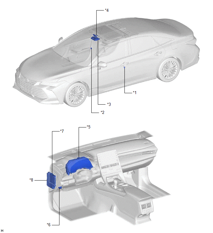
ILLUSTRATION
|
*1 | FRONT DOOR COURTESY LIGHT SWITCH ASSEMBLY (for LH) |
*2 | FRONT DOOR COURTESY LIGHT SWITCH ASSEMBLY (for RH) |
|
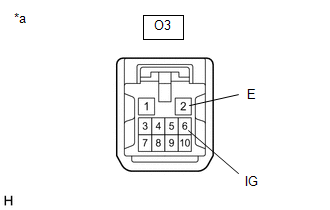
*3 | SLIDING ROOF SWITCH (ROOF CONSOLE BOX SUB-ASSEMBLY) |
*4 | SLIDING ROOF ECU (SLIDING ROOF DRIVE GEAR ASSEMBLY) |
|
*5 | COMBINATION METER ASSEMBLY |
*6 | DLC3 |
|
*7 | MAIN BODY ECU (MULTIPLEX NETWORK BODY ECU) |
*8 | INSTRUMENT PANEL JUNCTION BLOCK ASSEMBLY - S/ROOF FUSE - ECU-IG1 NO. 3 FUSE |
PRECAUTION
PRECAUTION FOR DISCONNECTING CABLE FROM NEGATIVE AUXILIARY BATTERY TERMINAL
NOTICE:
When disconnecting the cable from the negative (-) auxiliary battery terminal, initialize the following systems after the cable is reconnected.
|
System Name | See Procedure |
|---|---|
|
Lane Departure Alert System (w/ Steering Control) |
|
|
Intelligent Clearance Sonar System | |
|
Parking Assist Monitor System | |
|
Panoramic View Monitor System | |
|
Pre-collision System | |
|
Lighting System (for HV Model with Cornering Light) |
PROBLEM SYMPTOMS TABLE
HINT:
|
Symptom | Suspected Area |
Link |
|---|---|---|
| Remote control system does not operate |
Refer to the "Remote Control System does not Operate". |
|
|
Key-off operation function operates even if operating conditions are not satisfied |
Refer to the "Key-off Operation Function Operates even if Operating Conditions are not Satisfied". |
|
|
Sliding roof does not move by operating sliding roof control switch |
Refer to the "Sliding Roof does not Move by Operating Sliding Roof Control Switch". |
|
DESCRIPTION
The main body ECU (multiplex network body ECU) receives remote control signals from the driver door key cylinder or electrical key transmitter sub-assembly. Then, the main body ECU (multiplex network body ECU) activates the power window motor and sends the remote control signals to the sliding roof ECU (sliding roof drive gear assembly) via LIN communication. The sliding roof ECU (sliding roof drive gear assembly) receives those signals and activates the sliding roof motor.
CAUTION / NOTICE / HINT
NOTICE:
Click here 
Click here
Click here
Click here
Click here
PROCEDURE
|
1. | CHECK REMOTE CONTROL FUNCTION |
(a) Check the key-linked and wireless transmitter-linked functions.
Click here
|
Result | Proceed to |
|---|---|
|
Both the power windows and sliding roof operate by the key-linked and wireless transmitter-linked functions. |
A |
| The sliding roof does not operate by the key-linked or wireless transmitter-linked function, but all of the power windows operate. |
B |
| Both the power windows and sliding roof do not operate by the key-linked or wireless transmitter-linked function. |
C |
| A |
 | USE SIMULATION METHOD TO CHECK |
| C |
| GO TO POWER WINDOW CONTROL SYSTEM |
|
| 2. |
CHECK SLIDING ROOF OPERATION |
(a) Check the sliding roof operation.
Click here
OK:
Sliding roof operates normally.
| NG | | GO TO OTHER PROBLEM (Sliding Roof does not Move by Operating Sliding Roof Control Switch) |
|
| 3. |
REPLACE SLIDING ROOF ECU (SLIDING ROOF DRIVE GEAR ASSEMBLY) |
(a) Replace the sliding roof ECU (sliding roof drive gear assembly).
Click here
|
| 4. |
INITIALIZE SLIDING ROOF ECU (SLIDING ROOF DRIVE GEAR ASSEMBLY) |
(a) Initialize the sliding roof ECU (sliding roof drive gear assembly).
Click here
|
| 5. |
CHECK REMOTE CONTROL FUNCTION |
(a) Check the key-linked and wireless transmitter-linked functions.
Click here
OK:
The key-linked and wireless transmitter-linked functions operate normally.
| OK | | END (SLIDING ROOF ECU (SLIDING ROOF DRIVE GEAR ASSEMBLY) WAS DEFECTIVE) |
| NG | | REPLACE MAIN BODY ECU (MULTIPLEX NETWORK BODY ECU) |
DESCRIPTION
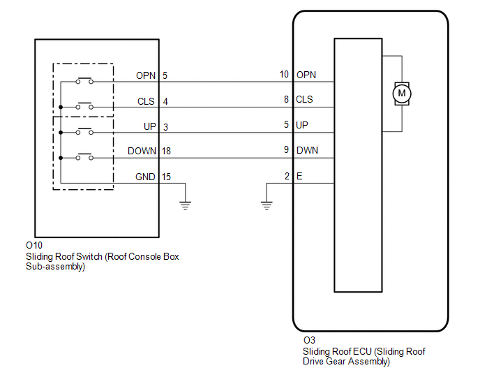
The sliding roof ECU (sliding roof drive gear assembly) receives slide and tilt signals and operates its built-in motor when the sliding roof switch (roof console box sub-assembly) is operated.
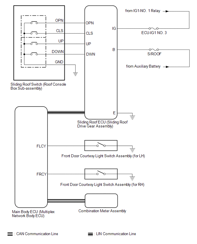
WIRING DIAGRAM
CAUTION / NOTICE / HINT
NOTICE:
Click here 
Click here
PROCEDURE
|
1. | PERFORM ACTIVE TEST USING TECHSTREAM (SLIDE ROOF) |
(a) Connect the Techstream to the DLC3.
(b) Turn the power switch on (IG).
(c) Turn the Techstream on.
(d) Enter the following menus: Body Electrical / Slide Roof / Active Test.
(e) Perform the Active Test according to the display on the Techstream.
Body Electrical > Sliding Roof > Active Test|
Tester Display | Measurement Item |
Control Range | Diagnostic Note |
|---|---|---|---|
|
Slide Roof | Operate sliding roof motor |
OFF / Opn/Dwn / Clos/Up |
- |
|
Tester Display |
|---|
| Slide Roof |
OK:
Slide roof is operated using Techstream.
| NG |  | GO TO STEP 5 |
|
| 2. |
READ VALUE USING TECHSTREAM |
(a) Enter the following menus: Body Electrical / Sliding Roof / Data List.
(b) Read the Data List according to the display on the Techstream.
Body Electrical > Sliding Roof > Data List|
Tester Display | Measurement Item |
Range | Normal Condition |
Diagnostic Note |
|---|---|---|---|---|
|
Open Switch | OPEN switch signal |
OFF or ON | OFF: OPEN switch not pressed ON: OPEN switch pressed |
- |
| Close Switch |
CLOSE switch signal | OFF or ON |
OFF: CLOSE switch not pressed ON: CLOSE switch pressed |
- |
| Up Switch |
UP switch signal | OFF or ON |
OFF: UP switch not pressed ON: UP switch pressed |
- |
| Down Switch |
DOWN switch signal | OFF or ON |
OFF: DOWN switch not pressed ON: DOWN switch pressed |
- |
|
Tester Display |
|---|
| Open Switch |
|
Close Switch |
| Up Switch |
|
Down Switch |
OK:
The Techstream display changes according to the operation of each switch as shown in the table.
| OK | | REPLACE SLIDING ROOF ECU (SLIDING ROOF DRIVE GEAR ASSEMBLY) |
|
| 3. |
INSPECT SLIDING ROOF SWITCH (ROOF CONSOLE BOX SUB-ASSEMBLY) |
(a) Remove the sliding roof switch (roof console box sub-assembly).
Click here
(b) Inspect the sliding roof switch (roof console box sub-assembly).
Click here
| NG | | REPLACE SLIDING ROOF SWITCH (ROOF CONSOLE BOX SUB-ASSEMBLY) |
|
| 4. |
CHECK HARNESS AND CONNECTOR (SLIDING ROOF ECU (SLIDING ROOF DRIVE GEAR ASSEMBLY) - SLIDING ROOF SWITCH (ROOF CONSOLE BOX SUB-ASSEMBLY) AND BODY GROUND) |
(a) Disconnect the O3 sliding roof ECU (sliding roof drive gear assembly) connector.
(b) Measure the resistance according to the value(s) in the table below.
Standard Resistance:
|
Tester Connection | Condition |
Specified Condition |
|---|---|---|
|
O3-8 (CLS) - O10-4 (CLS) |
Always | Below 1 Ω |
|
O3-8 (CLS) or O10-4 (CLS) - Body ground |
Always | 10 kΩ or higher |
|
O3-10 (OPN) - O10-5 (OPN) |
Always | Below 1 Ω |
|
O3-10 (OPN) or O10-5 (OPN) - Body ground |
Always | 10 kΩ or higher |
|
O3-9 (DWN) - O10-18 (DOWN) |
Always | Below 1 Ω |
|
O3-9 (DWN) or O10-18 (DOWN) - Body ground |
Always | 10 kΩ or higher |
|
O3-5 (UP) - O10-3 (UP) |
Always | Below 1 Ω |
|
O3-5 (UP) or O10-3 (UP) - Body ground |
Always | 10 kΩ or higher |
|
O10-15 (GND) - Body ground |
Always | Below 1 Ω |
|
O3-2 (E) - Body ground |
Always | Below 1 Ω |
| OK | | REPLACE SLIDING ROOF ECU (SLIDING ROOF DRIVE GEAR ASSEMBLY) |
| NG | | REPAIR OR REPLACE HARNESS OR CONNECTOR |
| 5. |
CHECK HARNESS AND CONNECTOR (SLIDING ROOF ECU (SLIDING ROOF DRIVE GEAR ASSEMBLY) - IG POWER SUPPLY AND BODY GROUND) |
| (a) Disconnect the O3 sliding roof ECU (sliding roof drive gear assembly) connector. |
|
(b) Measure the voltage according to the value(s) in the table below.
Standard Voltage:
|
Tester Connection | Condition |
Specified Condition |
|---|---|---|
|
O3-6 (IG) - Body ground |
Power switch on (IG) |
11 to 14 V |
|
O3-6 (IG) - Body ground |
Power switch off | Below 1 V |
(c) Measure the resistance according to the value(s) in the table below.
Standard Resistance:
|
Tester Connection | Condition |
Specified Condition |
|---|---|---|
|
O3-2 (E) - Body ground |
Always | Below 1 Ω |
| OK | | REPLACE SLIDING ROOF ECU (SLIDING ROOF DRIVE GEAR ASSEMBLY) |
| NG | | REPAIR OR REPLACE HARNESS OR CONNECTOR |
SYSTEM DESCRIPTION
SLIDING ROOF SYSTEM DESCRIPTION
(a) The sliding roof system controls the sliding roof operation using the sliding roof ECU (sliding roof drive gear assembly). Operating the sliding roof switch (roof console box sub-assembly) results in electrical power being transmitted to the sliding roof ECU (sliding roof drive gear assembly).
FUNCTION OF MAIN COMPONENT
The sliding roof system consists of the following components:
|
Component | Outline |
|---|---|
|
Sliding roof ECU (Sliding roof drive gear assembly) |
Controls the rotational direction of the motor, which tilts or slides the sliding roof. |
|
Sliding roof switch (Roof console box sub-assembly) |
Outputs operation signals to the sliding roof ECU (sliding roof drive gear assembly). |
SYSTEM FUNCTION
The sliding roof system has the following functions:
|
Function | Outline |
|---|---|
|
Manual slide open and close function |
This function causes the sliding roof to open (or close) when the OPEN switch (or CLOSE switch) is pressed for a maximum of 0.3 seconds. The sliding roof stops as soon as the switch is released. |
|
Auto slide open and close function | This function causes the sliding roof to reach the comfort stop position or fully open (or fully close) when the OPEN switch (or CLOSE switch) is pressed for a minimum of 0.3 seconds. |
|
Manual tilt up and down function | This function causes the sliding roof to tilt up (or tilt down) when the UP switch (or DOWN switch) is pressed for a maximum of 0.3 seconds. The sliding roof stops as soon as switch is released. |
|
Auto tilt up and down function | This function causes the sliding roof to fully tilt up (or tilt down) when the UP switch (or DOWN switch) is pressed for a minimum of 0.3 seconds. |
|
Jam protection function | The jam protection function automatically stops the sliding roof and moves it open halfway (or fully tilt up) if foreign matter gets jammed in the sliding roof during close or tilt down operation. |
|
Key-off operation function | The key-off operation function makes it possible to operate the sliding roof for approximately 45 seconds after the power switch is turned from on (IG) to off, if both the driver door and front passenger door are not opened. |
| Key-linked function* |
HINT: This function is linked with the power window key-linked function. |
|
Wireless transmitter-linked function* |
When the main body ECU (multiplex network body ECU) receives an unlock signal from the electrical key transmitter sub-assembly continuously for longer than 4 seconds, the sliding roof ECU (sliding roof drive gear assembly) activates the sliding roof motor to open the sliding roof while the switch of the electrical key transmitter sub-assembly is being pressed. HINT: This function is linked with the power window wireless transmitter-linked function. |
|
Sliding roof open warning function | When the power switch is turned from on (IG) and the driver door is opened with the sliding roof open, the buzzer in the combination meter assembly sounds once and a warning message is displayed on the multi-information display. |
SYSTEM DIAGRAM
 Communication Table
 |
Sender | Receiver |
Signal | Line |
|---|---|---|---|
|
Main Body ECU (Multiplex Network Body ECU) |
Sliding Roof ECU (Sliding Roof Drive Gear Assembly) |
| LIN |
|
Sliding Roof ECU (Sliding Roof Drive Gear Assembly) |
Main Body ECU (Multiplex Network Body ECU) |
Sliding roof position signal |
LIN |
| Combination Meter Assembly |
Main Body ECU (Multiplex Network Body ECU) |
Vehicle speed signal |
CAN |
| Main Body ECU (Multiplex Network Body ECU) |
Combination Meter Assembly | Sliding roof open warning request signal |
CAN |
TERMINALS OF ECU
CHECK SLIDING ROOF ECU (SLIDING ROOF DRIVE GEAR ASSEMBLY)

(a) Disconnect the O3 sliding roof ECU (sliding roof drive gear assembly) connector.
(b) Measure the resistance and voltage according to the value(s) in the table below.
HINT:
Measure the values on the wire harness side with the connector disconnected.
|
Terminal No. (Symbol) | Wiring Color |
Terminal Description | Condition |
Specified Condition |
|---|---|---|---|---|
|
O3-1 (B) - O3-2 (E) | B - W-B |
Auxiliary battery power supply |
Power switch off | 11 to 14 V |
|
O3-6 (IG) - O3-2 (E) |
LA-GR - W-B | IG power supply |
Power switch off | Below 1 V |
|
O3-6 (IG) - O3-2 (E) |
LA-GR - W-B | IG power supply |
Power switch on (IG) |
11 to 14 V |
|
O3-2 (E) - Body ground |
W-B - Body ground | Ground |
Always | Below 1 Ω |
(c) Reconnect the O3 sliding roof ECU (sliding roof drive gear assembly) connector.
(d) Measure the voltage according to the value(s) in the table below.
|
Terminal No. (Symbol) | Wiring Color |
Terminal Description | Condition |
Specified Condition |
|---|---|---|---|---|
|
O3-10 (OPN) - O3-2 (E) |
W - W-B | Sliding roof motor open |
Power switch on (IG), OPEN switch on |
Below 1 V |
|
O3-10 (OPN) - O3-2 (E) |
W - W-B | Sliding roof motor open |
Power switch on (IG), OPEN switch off |
11 to 14 V |
|
O3-8 (CLS) - O3-2 (E) |
SB - W-B | Sliding roof motor close |
Power switch on (IG), CLOSE switch on |
Below 1 V |
|
O3-8 (CLS) - O3-2 (E) |
SB - W-B | Sliding roof motor close |
Power switch on (IG), CLOSE switch off |
11 to 14 V |
|
O3-5 (UP) - O3-2 (E) |
R - W-B | Sliding roof motor up |
Power switch on (IG), UP switch on |
Below 1 V |
|
O3-5 (UP) - O3-2 (E) |
R - W-B | Sliding roof motor up |
Power switch on (IG), UP switch off |
11 to 14 V |
|
O3-9 (DWN) - O3-2 (E) |
LG - W-B | Sliding roof motor down |
Power switch on (IG), DOWN switch on |
Below 1 V |
|
O3-9 (DWN) - O3-2 (E) |
LG - W-B | Sliding roof motor down |
Power switch on (IG), DOWN switch off |
11 to 14 V |
CHECK MAIN BODY ECU (MULTIPLEX NETWORK BODY ECU)
Click here 
Toyota Avalon (XX50) 2019-2022 Service & Repair Manual > Can Communication System(for Hv Model): Open in Bus 1 Main Bus Line. Open in Bus 2 Main Bus Line. Open in Bus 3 Main Bus Line
Open in Bus 1 Main Bus Line DESCRIPTION There may be an open circuit in one of the CAN main bus lines when the resistance between terminals 23 (CA1H) and 8 (CA1L) of the central gateway ECU (network gateway ECU) is 70 Ω or higher. Symptom Trouble Area Resistance between terminals 23 (CA1H) and 8 (C ...