DESCRIPTION
The vehicle approaching speaker assembly circuit consists of the vehicle approaching speaker controller and vehicle approaching speaker assembly.
This DTC is stored when a malfunction is detected in the vehicle approaching speaker assembly circuit.
|
DTC No. | Detection Item |
DTC Detection Condition | Trouble Area |
|---|---|---|---|
|
B1350 | Speaker Circuit |
Either of the following conditions is met:
|
|
WIRING DIAGRAM
PROCEDURE
| 1. |
INSPECT VEHICLE APPROACHING SPEAKER ASSEMBLY |
(a) Remove the vehicle approaching speaker assembly.
Click here

(b) Inspect the vehicle approaching speaker assembly.
Click here
| NG |  | REPLACE VEHICLE APPROACHING SPEAKER ASSEMBLY |
|
| 2. |
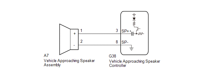
CHECK HARNESS AND CONNECTOR (VEHICLE APPROACHING SPEAKER ASSEMBLY - VEHICLE APPROACHING SPEAKER CONTROLLER) |
(a) Disconnect the G38 vehicle approaching speaker controller connector.
(b) Measure the resistance according to the value(s) in the table below.
Standard Resistance:
|
Tester Connection | Condition |
Specified Condition |
|---|---|---|
|
A7-1 (+) - G38-3 (SP+) |
Always | Below 1 Ω |
|
A7-2 (-) - G38-8 (SP-) |
Always | Below 1 Ω |
|
A7-1 (+) or G38-3 (SP+) - Body ground |
Always | 10 kΩ or higher |
|
A7-2 (-) or G38-8 (SP-) - Body ground |
Always | 10 kΩ or higher |
| OK | | REPLACE VEHICLE APPROACHING SPEAKER CONTROLLER |
| NG | | REPAIR OR REPLACE HARNESS OR CONNECTOR |
CUSTOMIZE PARAMETERS
CUSTOMIZE VEHICLE PROXIMITY NOTIFICATION SYSTEM
NOTICE:
HINT:
The following items can be customized.
(a) Customizing with the Techstream.
(1) Turn the power switch off.
(2) Connect the Techstream to the DLC3.
(3) Turn the power switch on (IG).
(4) Turn the Techstream on.
(5) Enter the following menus: Customize Setting / Others.
(6) Select the setting by referring to the table below.
Others|
Tester Display | Description |
Default | Setting |
ECU |
|---|---|---|---|---|
| Proximity Sound Volume Adjustment |
Function that sets the warning sound volume in 3 levels |
Standard | 010:Standard,011:Standard +1,100:Standard +2 |
Vehicle Approaching Speaker Controller |
|
Proximity Sound Level Increase (Vehicle Starting) |
Function that amplifies the warning sound when the vehicle starts off |
ON | 0:OFF,1:ON |
Vehicle Approaching Speaker Controller |
|
Proximity Sound Control (Vehicle Stationary) |
Function that sets the warning sound when the vehicle is stopped |
OFF | 0:OFF,1:ON |
Vehicle Approaching Speaker Controller |
DATA LIST / ACTIVE TEST
DATA LIST
NOTICE:
In the table below, the values listed under "Normal Condition" are reference values. Do not depend solely on these reference values when deciding whether a part is faulty or not.
HINT:
Using the Techstream to read the Data List allows the values or states of switches, sensors, actuators and other items to be read without removing any parts. This non-intrusive inspection can be very useful because intermittent conditions or signals may be discovered before parts or wiring is disturbed. Reading the Data List information early in troubleshooting is one way to save diagnostic time.
(a) Connect the Techstream to the DLC3.
(b) Turn the power switch on (IG).
(c) Turn the Techstream on.
(d) Enter the following menus: Body Electrical / Vehicle Proximity Notification System / Data List.
(e) Read the Data List according to the display on the Techstream.
Body Electrical > Vehicle Proximity Notification System > Data List|
Tester Display | Measurement Item |
Range | Normal Condition |
Diagnostic Note |
|---|---|---|---|---|
|
Stop Light SW | Stop light switch signal |
OFF or ON | OFF: Brake pedal released ON: Brake pedal depressed |
- |
| Permission Signal |
Vehicle proximity notification system permission signal |
OFF or ON | OFF: Vehicle proximity notification system operation prohibited (engine is operating or shift lever is in P). ON: Vehicle proximity notification system operation permitted (engine is stopped and shift lever is not in P). |
- |
| Vehicle Speed |
Vehicle speed | Min.: 0 km/h (0 mph), Max.: 255 km/h (158 mph) |
Almost the same as actual vehicle speed |
- |
| Proximity Sound Volume Adjustment |
Warning sound volume setting |
Standard, Standard +1 or Standard +2 |
Customized value displayed |
- |
| Proximity Sound Level Increase (Vehicle Starting) |
Warning sound amplifier function when vehicle starts off |
OFF or ON | Customized value displayed |
- |
| Proximity Sound Control (Vehicle Stationary) |
Warning sound setting function when vehicle stopped |
OFF or ON | Customized value displayed |
- |
| Number of DTC |
Number of trouble codes |
0 to 255 | Number of stored DTCs displayed |
- |
ACTIVE TEST
HINT:
Using the Techstream to perform Active Tests allows relays, VSVs, actuators and other items to be operated without removing any parts. This non-intrusive functional inspection can be very useful because intermittent operation may be discovered before parts or wiring is disturbed. Performing Active Tests early in troubleshooting is one way to save diagnostic time. Data List information can be displayed while performing Active Tests.
(a) Connect the Techstream to the DLC3.
(b) Turn the power switch on (IG).
(c) Turn the Techstream on.
(d) Enter the following menus: Body Electrical / Vehicle Proximity Notification System / Active Test.
(e) Perform the Active Test according to the display on the Techstream.
Body Electrical > Vehicle Proximity Notification System > Active Test|
Tester Display | Measurement Item |
Control Range | Diagnostic Note |
|---|---|---|---|
|
Proximity Sound Indicator |
Proximity sound indicator |
OFF or ON | - |
|
Proximity Sound (Vehicle Stationary) |
Proximity sound (Vehicle stationary) |
OFF or ON | Warning sound produced when vehicle is stopped |
|
Proximity Sound (Low Speed) |
Proximity sound (Low speed) |
OFF or ON | Warning sound produced when vehicle is being driven at speeds up to 10 km/h (6 mph) |
DIAGNOSTIC TROUBLE CODE CHART
Vehicle Proximity Notification System|
DTC No. | Detection Item |
Link |
|---|---|---|
| B1350 |
Speaker Circuit |
|
DTC CHECK / CLEAR
DTC CHECK
(a) Connect the Techstream to the DLC3.
(b) Turn the power switch on (IG).
(c) Turn the Techstream on.
(d) Enter the following menus: Body Electrical / Vehicle Proximity Notification System / Trouble Codes.
Body Electrical > Vehicle Proximity Notification System > Trouble Codes(e) Check for DTCs.
DTC CLEAR
(a) Connect the Techstream to the DLC3.
(b) Turn the power switch on (IG).
(c) Turn the Techstream on.
(d) Enter the following menus: Body Electrical / Vehicle Proximity Notification System / Trouble Codes.
Body Electrical > Vehicle Proximity Notification System > Clear DTCs(e) Clear the DTCs.
CAUTION / NOTICE / HINT
HINT:
PROCEDURE
|
1. | VEHICLE BROUGHT TO WORKSHOP |
|
| 2. |
CUSTOMER PROBLEM ANALYSIS AND SYMPTOM CHECK |
HINT:
|
What |
Vehicle model, system name |
|
When |
Date, time, occurrence frequency |
|
Where |
Road conditions |
|
Under what conditions? |
Driving conditions, weather conditions |
|
How did it happen? |
Problem symptoms |
|
| 3. |
PRE-CHECK |
(a) Measure the auxiliary battery voltage with the power switch off.
Standard Voltage:
11 to 14 V
If the voltage is below 11 V, recharge or replace the auxiliary battery before proceeding to the next step.
(b) Check the fuses and relays.
(c) Check the connector connections and terminals to make sure that there are no abnormalities such as loose connections, deformation, etc.
|
| 4. |
CHECK CAN COMMUNICATION SYSTEM* |
(a) Using the Techstream, check for CAN communication system DTCs.
Click here 
|
Result | Proceed to |
|---|---|
|
CAN DTCs are not output |
A |
| CAN DTCs are output |
B |
| B |
 | GO TO CAN COMMUNICATION SYSTEM |
|
| 5. |
CHECK LIGHTING SYSTEM |
(a) Check if the lighting system is functioning normally.
for HV Model with Cornering Light: Click here
for HV Model without Cornering Light: Click here
|
Result | Proceed to |
|---|---|
|
Lighting system is functioning normally |
A |
| Lighting system is not functioning normally |
B |
| B |
| GO TO LIGHTING SYSTEM |
|
| 6. |
CHECK METER / GAUGE SYSTEM* |
(a) Using the Techstream, check if the meter/gauge system is functioning normally.
Click here
|
Result | Proceed to |
|---|---|
|
No vehicle speed signal is mistakenly received |
A |
| A vehicle speed signal is mistakenly received |
B |
| B |
| GO TO METER / GAUGE SYSTEM |
|
| 7. |
CHECK HYBRID CONTROL SYSTEM |
(a) Check whether the hybrid control system is functioning normally.
Click here
|
Result | Proceed to |
|---|---|
|
Hybrid control system is functioning normally |
A |
| Hybrid control system is not functioning normally |
B |
| B |
| GO TO HYBRID CONTROL SYSTEM |
|
| 8. |
CHECK FOR DTC* |
(a) Check for DTCs.
Body Electrical > Vehicle Proximity Notification System > Trouble Codes|
Result | Proceed to |
|---|---|
|
DTCs are not output | A |
|
DTCs are output | B |
| B |
| GO TO DIAGNOSTIC TROUBLE CODE CHART |
|
| 9. |
PROBLEM SYMPTOMS TABLE |
(a) Refer to Problem Symptoms Table.
Click here
|
Result | Proceed to |
|---|---|
|
Fault is not listed in Problem Symptoms Table |
A |
| Fault is listed in Problem Symptoms Table |
B |
| B |
| GO TO PROBLEM SYMPTOMS TABLE |
|
| 10. |
OVERALL ANALYSIS AND TROUBLESHOOTING |
(a) Operation Check.
Click here
(b) Data List / Active Test
Click here
(c) Terminals of ECU
Click here
(d) Inspection
|
| 11. |
REPAIR OR REPLACE |
|
| 12. |
CONFIRMATION TEST |
| NEXT | | END |
OPERATION CHECK
VEHICLE PROXIMITY NOTIFICATION SYSTEM OPERATION CHECK
(a) System operation check (vehicle stopped)
(1) Apply the parking brake.
(2) Turn the power switch on (READY).
(3) With the brake pedal depressed, confirm that the vehicle proximity notification system does not operate (produce a sound) when the shift lever is moved from P to N.
(4) When the brake pedal is released, confirm that the vehicle proximity notification system operates for approximately 3 seconds (produces a sound).
(b) System operation check (vehicle being driven)
(1) Turn the power switch on (READY).
(2) Operate the EV drive mode switch and drive the vehicle using EV drive mode.
(3) When the shift lever is moved from P to D, confirm that the vehicle proximity notification system operates (produces a sound) when the vehicle is driven at speeds of 25 km/h (16 mph) or less using EV drive mode.
PARTS LOCATION
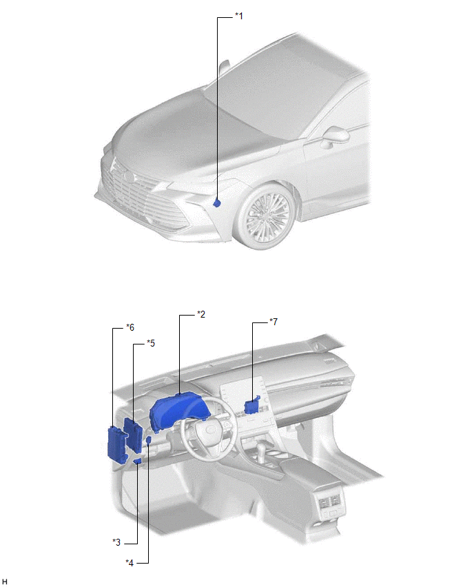
ILLUSTRATION
|
*1 | VEHICLE APPROACHING SPEAKER ASSEMBLY |
*2 | COMBINATION METER ASSEMBLY |
|
*3 | DLC3 |
*4 | STOP LIGHT SWITCH ASSEMBLY |
|
*5 | HYBRID VEHICLE CONTROL ECU |
*6 | INSTRUMENT PANEL JUNCTION BLOCK ASSEMBLY - ECU-IG1 NO. 3 FUSE |
|
*7 | VEHICLE APPROACHING SPEAKER CONTROLLER |
- | - |
PRECAUTION
PRECAUTION FOR DISCONNECTING CABLE FROM NEGATIVE AUXILIARY BATTERY TERMINAL
NOTICE:
When disconnecting the cable from the negative (-) auxiliary battery terminal, initialize the following systems after the cable is reconnected.
|
System Name | See Procedure |
|---|---|
|
Lane Departure Alert System (w/ Steering Control) |
|
|
Intelligent Clearance Sonar System | |
|
Parking Assist Monitor System | |
|
Panoramic View Monitor System | |
|
Pre-collision System | |
|
Lighting System (for HV Model with Cornering Light) |
PRECAUTIONS FOR VEHICLE PROXIMITY NOTIFICATION SYSTEM
(a) In the following cases, the volume or tone of the sound might change:
(1) If the vehicle is parked in a very hot or cold environment for an extended period of time (function will return to normal after time passes)
(2) If high pressure water is applied directly to the speaker from the bottom of the vehicle
(3) If the front of the speaker is blocked by mud, snow, ice, etc.
(4) If the entire speaker freezes
(b) In the following cases, it may be difficult to hear the sound from the speaker:
(1) If the environment around the vehicle is very noisy (in a busy intersection or when an emergency vehicle is approaching)
(2) If the listener is behind the vehicle. (Compared to a situation such as when a pedestrian is in front of the vehicle, the sound volume will seem to be lower when the car is reversing. This occurs because the speaker is installed facing the front of the vehicle.)
PROBLEM SYMPTOMS TABLE
HINT:
|
Symptom | Suspected Area |
Link |
|---|---|---|
| Sound is not produced |
Refer to "There is No Sound Made" |
|
|
When engine starts or shift lever is in P, sound does not stop |
Refer to "The Sound does not Stop when The Engine is Operated or when The Shift Lever is in P" |
|
|
Communication between vehicle proximity notification system (vehicle approaching speaker controller) and Techstream is not possible |
Refer to "Communication between Vehicle Proximity Notification System and Diagnostic Tool is not Possible" |
|
SYSTEM DESCRIPTION
VEHICLE PROXIMITY NOTIFICATION SYSTEM
(a) When the vehicle is being driven quietly using the motor only, the vehicle proximity notification system outputs a warning sound from the vehicle approaching speaker assembly to inform pedestrians, cyclists etc., of the approach of the vehicle.
(b) The warning sound is output by the vehicle approaching speaker assembly at a volume level that will not be perceived as noise. Also the pitch of the sound changes in accordance with vehicle speed so that the sound reflects vehicle deceleration and acceleration.
(c) Vehicle proximity notification system operation automatically stops when the vehicle is stopped, the engine starts or the vehicle is driven at 25 km/h (16 mph) or more.
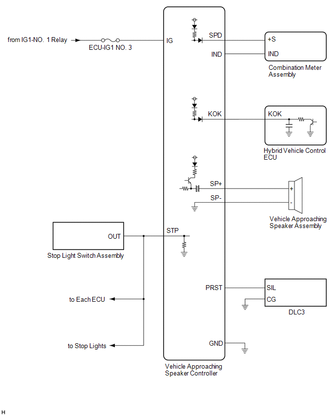
SYSTEM DIAGRAM
TERMINALS OF ECU
CHECK VEHICLE APPROACHING SPEAKER CONTROLLER

(a) Disconnect the G38 vehicle approaching speaker controller connector.
(b) Measure the voltage and resistance according to the value(s) in the table below.
|
Terminal No. (Symbol) | Wiring Color |
Terminal Description | Condition |
Specified Condition |
|---|---|---|---|---|
|
G38-1 (IG) - Body ground |
LA-B - Body ground |
IG power supply | Power switch on (IG) |
11 to 14 V |
|
Power switch off | Below 1 V | |||
|
G38-7 (GND) - Body ground |
W-B - Body ground | Ground |
Always | Below 1 Ω |
(c) Connect the G38 vehicle approaching speaker controller connector.
(d) Measure the voltage and check for pulses according to the value(s) in the table below.
|
Terminal No. (Symbol) | Wiring Color |
Terminal Description | Condition |
Specified Condition |
|---|---|---|---|---|
|
G38-2 (STP) - G38-7 (GND) |
LA-L - W-B |
Stop light signal input |
Power switch off, brake pedal depressed |
8 V or higher |
|
Power switch off, brake pedal released |
Below 1 V | |||
|
G38-3 (SP+) - G38-8 (SP-) |
P - LG | Vehicle approaching speaker output |
Vehicle approaching speaker operating |
A waveform synchronized with the sound is output (See Waveform 1) |
|
G38-6 (SPD) - G38-7 (GND) |
G - W-B | Speed signal input |
Power switch on (IG), wheel being rotated |
Pulse generation (See Waveform 2) |
|
G38-9 (PRST) - G38-7 (GND) |
LG - W-B | SIL communication signal |
Power switch on (IG), communication occurring |
Pulse generation (See Waveform 3) |
|
G38-10 (IND) - G38-7 (GND) |
B - W-B | Warning signal output |
Approximately 3 seconds after turning power switch on (IG) |
Below 1 V |
|
G38-11 (KOK) - G38-7 (GND) |
BE - W-B |
Permission signal | Power switch on (READY), shift lever in P |
Below 2.3 V |
|
Power switch on (READY), engine stopped and shift lever not in P |
8 V or higher |
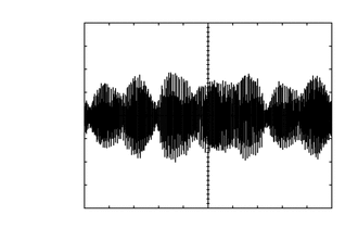
(1) Waveform 1
|
Item | Condition |
|---|---|
|
Tester Connection | G38-3 (SP+) - G38-8 (SP-) |
|
Tool Setting | 1 V/DIV., 200 ms./DIV. |
|
Condition | Vehicle approaching speaker operating |
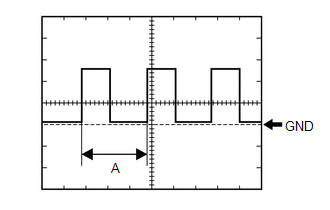
(2) Waveform 2
|
Item | Condition |
|---|---|
|
Tester Connection | G38-6 (SPD) - G38-7 (GND) |
|
Tool Setting | 5 V/DIV., 20 ms./DIV. |
|
Condition | Power switch on (IG), wheel being rotated |
HINT:
When the system is functioning normally, one wheel revolution generates 4 pulses. As the vehicle speed increases, the width indicated by (A) in the illustration narrows.
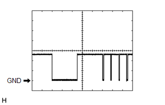
(3) Waveform 3
|
Item | Condition |
|---|---|
|
Tester Connection | G38-9 (PRST) - G38-7 (GND) |
|
Tool Setting | 5 V/DIV., 10 ms./DIV. |
|
Condition | Power switch on (IG), communication occurring |
CHECK HYBRID VEHICLE CONTROL ECU
Click here

Toyota Avalon (XX50) 2019-2022 Service & Repair Manual > 2gr-fks Engine Control: Ecm
Components COMPONENTS ILLUSTRATION *1 AIR CLEANER ASSEMBLY WITH AIR CLEANER HOSE *2 COOL AIR INTAKE DUCT SEAL *3 ECM *4 INLET AIR CLEANER ASSEMBLY *5 NO. 1 ECM BRACKET *6 NO. 2 ECM BRACKET *7 VACUUM HOSE *8 NO. 1 FUEL VAPOR FEED HOSE *9 NO. 2 VENTILATION HOSE - - N*m (kgf*cm, ft.*lbf): Specified tor ...


