DESCRIPTION
Wireless Transmitter-linked FunctionCAUTION / NOTICE / HINT
NOTICE:
Click here 
Click here
PROCEDURE
|
1. | CHECK BASIC FUNCTION (WIRELESS AND POWER DOOR LOCK CONTROL SYSTEM) |
(a) Check that the wireless door lock / unlock function operates normally.
Click here
(b) Check that the key-linked lock/unlock function operates normally.
Click here
|
Result | Proceed to |
|---|---|
|
Wireless door lock/unlock function and key-linked lock/unlock function operate normally |
A |
| Wireless door lock/unlock function does not operate normally |
B |
| Key-linked lock/unlock function does not operate normally |
C |
| B |
 | GO TO WIRELESS DOOR LOCK CONTROL SYSTEM (Proceed to Problem Symptoms Table) |
| C |
| GO TO POWER DOOR LOCK CONTROL SYSTEM (Proceed to Problem Symptoms Table) |
|
| 2. |
CHECK MANUAL UP / DOWN FUNCTION |
(a) Check that the manual up and down functions using the multiplex network master switch assembly, power window regulator switch assembly and rear power window regulator switch assemblies can operate all of the power windows.
Click here
OK:
Manual up and down functions are normal.
| NG | | GO TO OTHER PROBLEM (Proceed to Problem Symptoms Table) |
|
| 3. |
CHECK REMOTE UP / DOWN FUNCTION |
(a) Check that the remote up and down functions using the multiplex network master switch assembly can operate all of the power windows.
Click here
OK:
Remote up and down functions are normal.
| OK | | REPLACE MAIN BODY ECU (MULTIPLEX NETWORK BODY ECU) |
| NG | | GO TO OTHER PROBLEM (Proceed to Problem Symptoms Table) |
DESCRIPTION
If a door glass does not slide smoothly or a power window regulator motor assembly or door window regulator sub-assembly does not operate smoothly, the catch protection function may be triggered automatically, resulting in the auto down operation being unable to fully open the power window.
CAUTION / NOTICE / HINT
NOTICE:
Click here 
Click here
HINT:
This symptom may occur for any of the power windows.
PROCEDURE
| 1. |
PERFORM INITIALIZATION (APPLICABLE LOCATION) |
(a) Initialize the power window regulator motor assembly (applicable location).
Click here
|
| 2. |
CHECK POWER WINDOW CONTROL SYSTEM (AUTO UP / DOWN FUNCTION (APPLICABLE LOCATION)) |
(a) Check that each power window moves when the auto up and down functions of the multiplex network master switch assembly or power window regulator switch assembly or rear power window regulator switch assembly is operated.
Click here
OK:
Auto up and down functions are normal (applicable location).
| OK |  | END (PROBLEM DUE TO INITIALIZATION FAILURE) |
|
| 3. |
CHECK DOOR GLASS SLIDING MOVEMENT (APPLICABLE LOCATION) |
(a) Remove the power window regulator motor assembly and door window regulator sub-assembly.
(b) Install the door glass to the door glass run.
(c) Check that the power window regulator motor assembly and door window regulator sub-assembly operate smoothly.
(d) Check that the door glass slides smoothly when sliding it down by hand.
NOTICE:
Make sure to perform initialization again.
HINT:
Ensure the following:OK:
Door glass slides smoothly.
|
Result | Proceed to |
|---|---|
|
OK (Driver door power window) |
A |
| OK (Front passenger door power window) | |
|
OK (Rear LH door power window) |
B |
| OK (Rear RH door power window) | |
|
NG | C |
| A |
| REPLACE POWER WINDOW REGULATOR MOTOR ASSEMBLY (for Driver Door or Front Passenger Door) |
| B |
| REPLACE POWER WINDOW REGULATOR MOTOR ASSEMBLY (for Rear LH Door or Rear RH Door) |
| C |
| FIT DOOR GLASS CORRECTLY (REMOVE FOREIGN MATTER CAUSING IMPROPER FIT OR REPLACE PARTS) |
DESCRIPTION
If a door glass does not slide smoothly or a power window regulator motor assembly or door window regulator sub-assembly does not operate smoothly, the jam protection function may be triggered automatically, resulting in the auto up operation being unable to fully close the power window.
CAUTION / NOTICE / HINT
NOTICE:
Click here 
Click here
HINT:
This symptom may occur for any of the power windows.
PROCEDURE
| 1. |
PERFORM INITIALIZATION (APPLICABLE LOCATION) |
(a) Initialize the power window regulator motor assembly (applicable location).
Click here
|
| 2. |
CHECK POWER WINDOW CONTROL SYSTEM (AUTO UP / DOWN FUNCTION (APPLICABLE LOCATION)) |
(a) Check that each power window moves when the auto up and down functions of the multiplex network master switch assembly, power window regulator switch assembly or rear power window regulator switch assembly are operated.
Click here
OK:
Auto up and down functions are normal (applicable location).
| OK |  | END (PROBLEM DUE TO INITIALIZATION FAILURE) |
|
| 3. |
CHECK DOOR GLASS SLIDING MOVEMENT (APPLICABLE LOCATION) |
(a) Remove the power window regulator motor assembly and door window regulator sub-assembly.
(b) Install the door glass to the door glass run.
(c) Check that the power window regulator motor assembly and door window regulator sub-assembly operate smoothly.
(d) Check that the door glass slides smoothly when sliding it up by hand.
NOTICE:
Make sure to perform initialization again.
HINT:
Ensure the following:OK:
Door glass slides smoothly.
|
Result | Proceed to |
|---|---|
|
OK (Driver door power window) |
A |
| OK (Front passenger door power window) | |
|
OK (Rear LH door power window) |
B |
| OK (Rear RH door power window) | |
|
NG | C |
| A |
| REPLACE POWER WINDOW REGULATOR MOTOR ASSEMBLY (for Driver Door or Front Passenger Door) |
| B |
| REPLACE POWER WINDOW REGULATOR MOTOR ASSEMBLY (for Rear LH Door or Rear RH Door) |
| C |
| FIT DOOR GLASS CORRECTLY (REMOVE FOREIGN MATTER CAUSING IMPROPER FIT OR REPLACE PARTS) |
DESCRIPTION
The power window regulator motor assemblies are operated by the multiplex network master switch assembly, power window regulator switch assembly or rear power window regulator switch assemblies. The power window regulator motor assemblies have motor, regulator and ECU functions.
This DTC is stored when a power window regulator motor assembly is malfunctioning, or the ECU built into the power window regulator motor assembly determines that the fully closed power window position has deviated approximately 20 mm (0.787 in.) or more from the normal position.
D-Door Motor|
DTC No. | Detection Item |
DTC Detection Condition | Trouble Area |
|---|---|---|---|
|
B2311 | Power Window Motor Malfunction |
|
|
|
DTC No. | Detection Item |
DTC Detection Condition | Trouble Area |
|---|---|---|---|
|
B2311 | Power Window Motor Malfunction |
|
|
|
DTC No. | Detection Item |
DTC Detection Condition | Trouble Area |
|---|---|---|---|
|
B2311 | Power Window Motor Malfunction |
|
|
|
DTC No. | Detection Item |
DTC Detection Condition | Trouble Area |
|---|---|---|---|
|
B2311 | Power Window Motor Malfunction |
|
|
WIRING DIAGRAM

CAUTION / NOTICE / HINT
NOTICE:
Click here 
Click here
Click here
PROCEDURE
|
1. | CHECK FOR DTC |
(a) Connect the Techstream to the DLC3.
(b) Turn the power switch on (IG).
(c) Turn the Techstream on.
(d) Enter the following menus: Body Electrical / (desired system) / Clear DTCs.
(e) Clear the DTCs.
Body Electrical > D-Door Motor > Clear DTCs Body Electrical > P-Door Motor > Clear DTCs Body Electrical > RL-Door Motor > Clear DTCs Body Electrical > RR-Door Motor > Clear DTCs(f) Check for DTCs.
Body Electrical > D-Door Motor > Trouble Codes Body Electrical > P-Door Motor > Trouble Codes Body Electrical > RL-Door Motor > Trouble Codes Body Electrical > RR-Door Motor > Trouble CodesOK:
DTC B2311 is not output.
| OK |  | USE SIMULATION METHOD TO CHECK |
|
| 2. |
CHECK DTC OUTPUT |
(a) Check the parts from which this DTC has been output.
|
Result | Proceed to |
|---|---|
|
DTC output from power window regulator motor assembly (for driver door) |
A |
| DTC output from power window regulator motor assembly (for front passenger door) |
B |
| DTC output from power window regulator motor assembly (for rear LH door) |
C |
| DTC output from power window regulator motor assembly (for rear RH door) |
D |
| B |
| GO TO STEP 4 |
| C |
| GO TO STEP 5 |
| D |
| GO TO STEP 6 |
|
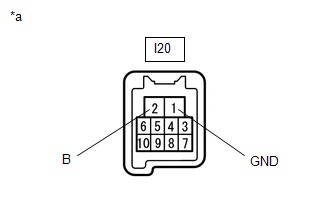
| 3. |
CHECK HARNESS AND CONNECTOR (POWER WINDOW REGULATOR MOTOR ASSEMBLY (for Driver Door) - AUXILIARY BATTERY AND BODY GROUND) |
| (a) Measure the voltage according to the value(s) in the table below. Standard Voltage:
|
|
(b) Measure the resistance according to the value(s) in the table below.
Standard Resistance:
|
Tester Connection | Condition |
Specified Condition |
|---|---|---|
|
I20-1 (GND) - Body ground |
Always | Below 1 Ω |
| OK | | GO TO STEP 7 |
| NG | | REPAIR OR REPLACE HARNESS OR CONNECTOR |
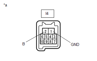
| 4. |
CHECK HARNESS AND CONNECTOR (POWER WINDOW REGULATOR MOTOR ASSEMBLY (for Front Passenger Door) - AUXILIARY BATTERY AND BODY GROUND) |
| (a) Measure the voltage according to the value(s) in the table below. Standard Voltage:
|
|
(b) Measure the resistance according to the value(s) in the table below.
Standard Resistance:
|
Tester Connection | Condition |
Specified Condition |
|---|---|---|
|
I4-1 (GND) - Body ground |
Always | Below 1 Ω |
| OK | | GO TO STEP 7 |
| NG | | REPAIR OR REPLACE HARNESS OR CONNECTOR |
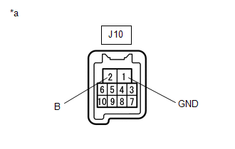
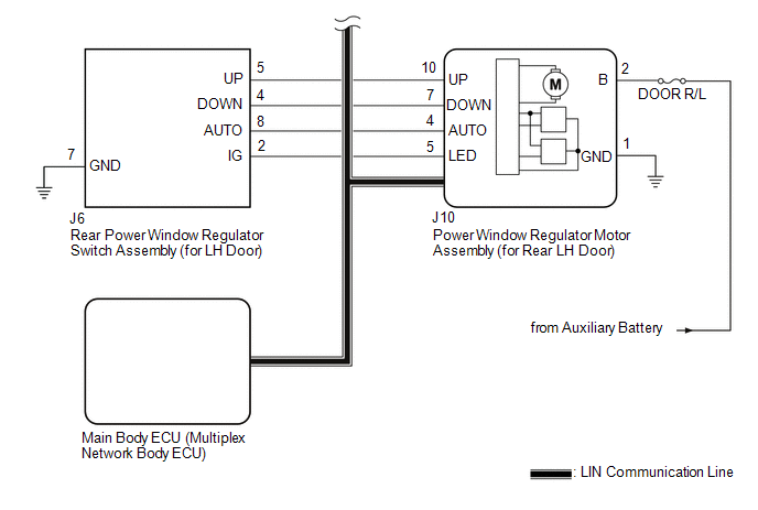
| 5. |
CHECK HARNESS AND CONNECTOR (POWER WINDOW REGULATOR MOTOR ASSEMBLY (for Rear LH Door) - AUXILIARY BATTERY AND BODY GROUND) |
| (a) Measure the voltage according to the value(s) in the table below. Standard Voltage:
|
|
(b) Measure the resistance according to the value(s) in the table below.
Standard Resistance:
|
Tester Connection | Condition |
Specified Condition |
|---|---|---|
|
J10-1 (GND) - Body ground |
Always | Below 1 Ω |
| OK | | GO TO STEP 7 |
| NG | | REPAIR OR REPLACE HARNESS OR CONNECTOR |
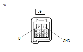
| 6. |
CHECK HARNESS AND CONNECTOR (POWER WINDOW REGULATOR MOTOR ASSEMBLY (for Rear RH Door) - AUXILIARY BATTERY AND BODY GROUND) |
| (a) Measure the voltage according to the value(s) in the table below. Standard Voltage:
|
|
(b) Measure the resistance according to the value(s) in the table below.
Standard Resistance:
|
Tester Connection | Condition |
Specified Condition |
|---|---|---|
|
J9-1 (GND) - Body ground |
Always | Below 1 Ω |
| NG | | REPAIR OR REPLACE HARNESS OR CONNECTOR |
|
| 7. |
PERFORM ACTIVE TEST USING TECHSTREAM (APPLICABLE LOCATION) |
(a) Enter the following menus: Body Electrical / (desired system) / Active Test.
HINT:
Perform the Active Test for the power window regulator motor assembly that has DTC B2311 stored in its ECU.
(b) Perform the Active Test according to the display on the Techstream.
CAUTION:
Be careful to avoid injuries as this test causes vehicle parts to move. During the Active Test, the jam protection function will not operate.
Body Electrical > D-Door Motor > Active Test|
Tester Display | Measurement Item |
Control Range | Diagnostic Note |
|---|---|---|---|
|
Power Window | Power window |
OFF / DOWN / UP | - |
|
Tester Display | Measurement Item |
Control Range | Diagnostic Note |
|---|---|---|---|
|
Power Window | Power window |
OFF / DOWN / UP | - |
|
Tester Display | Measurement Item |
Control Range | Diagnostic Note |
|---|---|---|---|
|
Power Window | Power window |
OFF / DOWN / UP | - |
|
Tester Display | Measurement Item |
Control Range | Diagnostic Note |
|---|---|---|---|
|
Power Window | Power window |
OFF / DOWN / UP | - |
|
Tester Display |
|---|
| Power Window |
|
Tester Display |
|---|
| Power Window |
|
Tester Display |
|---|
| Power Window |
|
Tester Display |
|---|
| Power Window |
OK:
Each power window operates normally.
|
Result | Proceed to |
|---|---|
|
OK | A |
|
NG (Driver door power window) |
B |
| NG (Front passenger door power window) | |
|
NG (Rear LH door power window) |
C |
| NG (Rear RH door power window) |
| B |
| REPLACE POWER WINDOW REGULATOR MOTOR ASSEMBLY (for Driver Door or Front Passenger Door) |
| C |
| REPLACE POWER WINDOW REGULATOR MOTOR ASSEMBLY (for Rear LH Door or Rear RH Door) |
|
| 8. |
PERFORM INITIALIZATION (APPLICABLE LOCATION) |
(a) Initialize the power window regulator motor assembly.
Click here
HINT:
Initialize the power window regulator motor assembly that has DTC B2311 stored in its ECU.
|
| 9. |
CHECK POWER WINDOW CONTROL SYSTEM (APPLICABLE LOCATION) |
(a) Check that the power window operates normally by opening and closing it.
Click here
HINT:
Check the power window operation of the window where DTC B2311 has been stored.
OK:
Each power window operates normally.
|
Result | Proceed to |
|---|---|
|
OK | A |
|
NG (Driver door power window) |
B |
| NG (Front passenger door power window) | |
|
NG (Rear LH door power window) |
C |
| NG (Rear RH door power window) |
| B |
| REPLACE POWER WINDOW REGULATOR MOTOR ASSEMBLY (for Driver Door or Front Passenger Door) |
| C |
| REPLACE POWER WINDOW REGULATOR MOTOR ASSEMBLY (for Rear LH Door or Rear RH Door) |
|
| 10. |
CHECK WHETHER PARTS HAVE BEEN INSTALLED CORRECTLY |
(a) Check that the power window components are installed correctly.
HINT:
Initialize the power window regulator motor assembly that has DTC B2311 stored in its ECU.
OK:
Power window components are installed correctly.
| NG | | INSTALL PARTS CORRECTLY |
|
| 11. |
CHECK DTC OUTPUT |
(a) Turn the power switch off.
(b) Wait for at least 10 seconds, and then turn the power switch on (IG).
(c) Check for DTCs.
Body Electrical > D-Door Motor > Trouble Codes Body Electrical > P-Door Motor > Trouble Codes Body Electrical > RL-Door Motor > Trouble Codes Body Electrical > RR-Door Motor > Trouble CodesOK:
B2311 is not output.
|
Result | Proceed to |
|---|---|
|
OK | A |
|
NG (Driver door power window) |
B |
| NG (Front passenger door power window) | |
|
NG (Rear LH door power window) |
C |
| NG (Rear RH door power window) |
| A |
| END |
| B |
| REPLACE POWER WINDOW REGULATOR MOTOR ASSEMBLY (for Driver Door or Front Passenger Door) |
| C |
| REPLACE POWER WINDOW REGULATOR MOTOR ASSEMBLY (for Rear LH Door or Rear RH Door) |
DESCRIPTION
The power window regulator motor assemblies are operated by the multiplex network master switch assembly, power window regulator switch assembly or rear power window regulator switch assemblies. The power window regulator motor assemblies have motor, regulator and ECU functions.
This DTC is stored when the ECU built into a power window regulator motor assembly and multiplex network master switch assembly determine that the multiplex network master switch assembly, power window regulator switch assembly or rear power window regulator switch assembly is stuck.
Master Switch|
DTC No. | Detection Item |
DTC Detection Condition | Trouble Area |
|---|---|---|---|
|
B2312 | Power Window Switch Malfunction |
| Multiplex network master switch assembly |
|
DTC No. | Detection Item |
DTC Detection Condition | Trouble Area |
|---|---|---|---|
|
B2312 | Power Window Switch Malfunction |
|
|
|
DTC No. | Detection Item |
DTC Detection Condition | Trouble Area |
|---|---|---|---|
|
B2312 | Power Window Switch Malfunction |
|
|
|
DTC No. | Detection Item |
DTC Detection Condition | Trouble Area |
|---|---|---|---|
|
B2312 | Power Window Switch Malfunction |
|
|
|
DTC No. | Detection Item |
DTC Detection Condition | Trouble Area |
|---|---|---|---|
|
B2312 | Power Window Switch Malfunction |
|
|
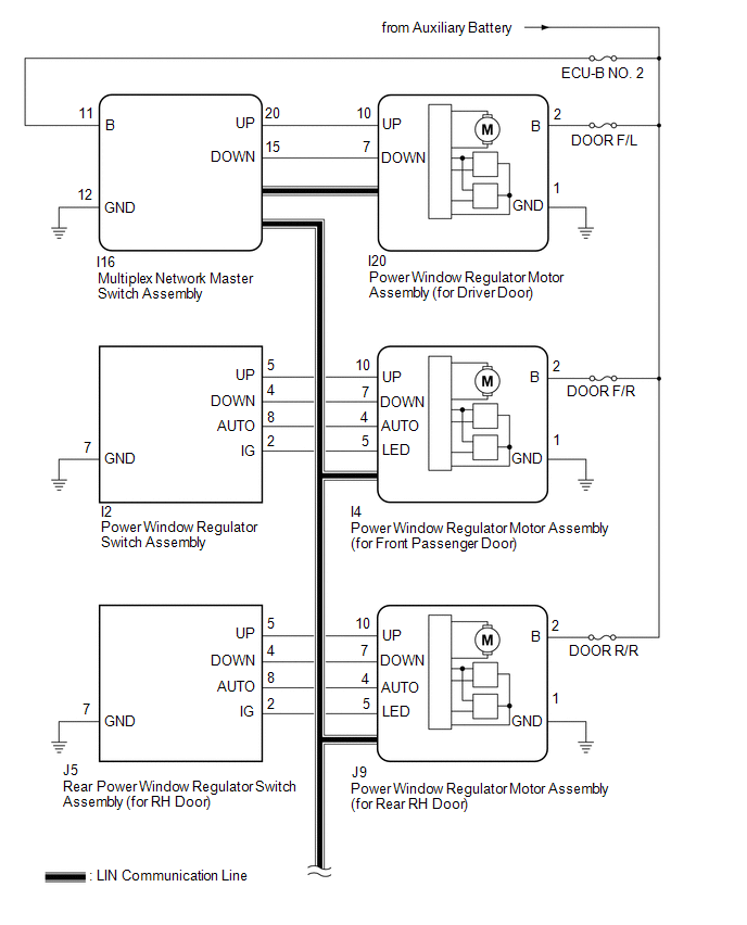
WIRING DIAGRAM

CAUTION / NOTICE / HINT
NOTICE:
Click here 
Click here
HINT:
If DTC B2312 is not output again after the DTC has been cleared, the DTC was stored due to the switch being held in the same position continuously.
PROCEDURE
| 1. |
CHECK FOR DTC |
(a) Connect the Techstream to the DLC3.
(b) Turn the power switch on (IG).
(c) Turn the Techstream on.
(d) Enter the following menus: Body Electrical / (desired system) / Clear DTCs.
(e) Clear the DTCs.
Body Electrical > Master Switch > Clear DTCs Body Electrical > D-Door Motor > Clear DTCs Body Electrical > P-Door Motor > Clear DTCs Body Electrical > RL-Door Motor > Clear DTCs Body Electrical > RR-Door Motor > Clear DTCs(f) Check for DTCs.
Body Electrical > Master Switch > Trouble Codes Body Electrical > D-Door Motor > Trouble Codes Body Electrical > P-Door Motor > Trouble Codes Body Electrical > RL-Door Motor > Trouble Codes Body Electrical > RR-Door Motor > Trouble CodesOK:
DTC B2312 is not output.
| OK |  | END (DTC WAS STORED DUE TO SWITCH BEING OPERATED FOR 20 SECONDS OR MORE) |
|
| 2. |
CHECK DTC OUTPUT |
(a) Check the parts from which this DTC has been output.
|
Result | Proceed to |
|---|---|
|
DTC output from multiplex network master switch assembly |
A |
| DTC output from power window regulator motor assembly (for driver door) |
B |
| DTC output from power window regulator motor assembly (for front passenger door) |
C |
| DTC output from power window regulator motor assembly (for rear LH door) |
D |
| DTC output from power window regulator motor assembly (for rear RH door) |
E |
| A |
| REPLACE MULTIPLEX NETWORK MASTER SWITCH ASSEMBLY |
| C |
| GO TO STEP 6 |
| D |
| GO TO STEP 9 |
| E |
| GO TO STEP 12 |
|
| 3. |
READ VALUE USING TECHSTREAM (D-DOOR MOTOR) |
(a) Enter the following menus: Body Electrical / D-Door Motor / Data List.
(b) Read the Data List according to the display on the Techstream.
Body Electrical > D-Door Motor > Data List|
Tester Display | Measurement Item |
Range | Normal Condition |
Diagnostic Note |
|---|---|---|---|---|
|
D Door P/W Up SW | Driver door power window manual up switch signal |
OFF or ON | OFF: Driver door power window manual up switch not being operated ON: Driver door power window manual up switch being operated |
- |
| D Door P/W Down SW |
Driver door power window manual down switch signal |
OFF or ON | OFF: Driver door power window manual down switch not being operated ON: Driver door power window manual down switch being operated |
- |
|
Tester Display |
|---|
| D Door P/W Up SW |
|
D Door P/W Down SW |
OK:
On the Techstream screen, ON or OFF is displayed accordingly.
| OK | | REPLACE POWER WINDOW REGULATOR MOTOR ASSEMBLY (for Driver Door) |
|
| 4. |
CHECK MULTIPLEX NETWORK MASTER SWITCH ASSEMBLY |
| (a) Disconnect the I20 power window regulator motor assembly (for driver door) connector. |
|
(b) Measure the voltage according to the value(s) in the table below.
Standard Voltage:
|
Tester Connection | Condition |
Specified Condition |
|---|---|---|
|
I20-10 (UP) - Body ground |
Power switch on (IG) |
11 to 14 V |
|
I20-7 (DOWN) - Body ground |
Power switch on (IG) |
11 to 14 V |
| OK | | REPLACE POWER WINDOW REGULATOR MOTOR ASSEMBLY (for Driver Door) |
|
| 5. |
CHECK HARNESS AND CONNECTOR (MULTIPLEX NETWORK MASTER SWITCH ASSEMBLY - POWER WINDOW REGULATOR MOTOR ASSEMBLY (for Driver Door)) |
(a) Disconnect the I16 multiplex network master switch assembly connector.
(b) Measure the resistance according to the value(s) in the table below.
Standard Resistance:
|
Tester Connection | Condition |
Specified Condition |
|---|---|---|
|
I16-20 (UP) or I20-10 (UP) - Body ground |
Always | 10 kΩ or higher |
|
I16-15 (DOWN) or I20-7 (DOWN) - Body ground |
Always | 10 kΩ or higher |
| OK | | REPLACE MULTIPLEX NETWORK MASTER SWITCH ASSEMBLY |
| NG | | REPAIR OR REPLACE HARNESS OR CONNECTOR |
| 6. |
READ VALUE USING TECHSTREAM (P-DOOR MOTOR) |
(a) Enter the following menus: Body Electrical / P-Door Motor / Data List.
(b) Read the Data List according to the display on the Techstream.
Body Electrical > P-Door Motor > Data List|
Tester Display | Measurement Item |
Range | Normal Condition |
Diagnostic Note |
|---|---|---|---|---|
|
P Door P/W Auto SW | Front passenger door power window auto switch signal |
OFF or ON | OFF: Front passenger door power window auto up or auto down switch not being operated ON: Front passenger door power window auto up or auto down switch being operated |
- |
| P Door P/W Up SW |
Front passenger door power window manual up switch signal |
OFF or ON | OFF: Front passenger door power window manual up switch not being operated ON: Front passenger door power window manual up switch being operated |
- |
| P Door P/W Down SW |
Front passenger door power window manual down switch signal |
OFF or ON | OFF: Front passenger door power window manual down switch not being operated ON: Front passenger door power window manual down switch being operated |
- |
|
Tester Display |
|---|
| P Door P/W Auto SW |
|
P Door P/W Up SW |
|
P Door P/W Down SW |
OK:
On the Techstream screen, ON or OFF is displayed accordingly.
| OK | | REPLACE POWER WINDOW REGULATOR MOTOR ASSEMBLY (for Front Passenger Door) |
|
| 7. |
INSPECT POWER WINDOW REGULATOR SWITCH ASSEMBLY |
(a) Remove the power window regulator switch assembly.
Click here
(b) Inspect the power window regulator switch assembly.
Click here
| NG | | REPLACE POWER WINDOW REGULATOR SWITCH ASSEMBLY |
|
| 8. |
CHECK HARNESS AND CONNECTOR (POWER WINDOW REGULATOR SWITCH ASSEMBLY - POWER WINDOW REGULATOR MOTOR ASSEMBLY (for Front Passenger Door)) |
(a) Disconnect the I4 power window regulator motor assembly (for front passenger door) connector.
(b) Measure the resistance according to the value(s) in the table below.
Standard Resistance:
|
Tester Connection | Condition |
Specified Condition |
|---|---|---|
|
I2-5 (UP) or I4-10 (UP) - Body ground |
Always | 10 kΩ or higher |
|
I2-4 (DOWN) or I4-7 (DOWN) - Body ground |
Always | 10 kΩ or higher |
|
I2-8 (AUTO) or I4-4 (AUTO) - Body ground |
Always | 10 kΩ or higher |
| OK | | REPLACE POWER WINDOW REGULATOR MOTOR ASSEMBLY (for Front Passenger Door) |
| NG | | REPAIR OR REPLACE HARNESS OR CONNECTOR |
| 9. |
READ VALUE USING TECHSTREAM (RL-DOOR MOTOR) |
(a) Enter the following menus: Body Electrical / RL-Door Motor / Data List.
(b) Read the Data List according to the display on the Techstream.
Body Electrical > RL-Door Motor > Data List|
Tester Display | Measurement Item |
Range | Normal Condition |
Diagnostic Note |
|---|---|---|---|---|
|
RL Door P/W Auto SW | Rear LH door power window auto switch signal |
OFF or ON | OFF: Rear LH door power window auto up or auto down switch not being operated ON: Rear LH door power window auto up or auto down switch being operated |
- |
| RL Door P/W Up SW |
Rear LH door power window manual up switch signal |
OFF or ON | OFF: Rear LH door power window manual up switch not being operated ON: Rear LH door power window manual up switch being operated |
- |
| RL Door P/W Down SW |
Rear LH door power window manual down switch signal |
OFF or ON | OFF: Rear LH door power window manual down switch not being operated ON: Rear LH door power window manual down switch being operated |
- |
|
Tester Display |
|---|
| RL Door P/W Auto SW |
|
RL Door P/W Up SW |
|
RL Door P/W Down SW |
OK:
On the Techstream screen, ON or OFF is displayed accordingly.
| OK | | REPLACE POWER WINDOW REGULATOR MOTOR ASSEMBLY (for Rear LH Door) |
|
| 10. |
INSPECT REAR POWER WINDOW REGULATOR SWITCH ASSEMBLY (for LH Door) |
(a) Remove the rear power window regulator switch assembly (for LH door).
Click here
(b) Inspect the rear power window regulator switch assembly (for LH door).
Click here
| NG | | REPLACE REAR POWER WINDOW REGULATOR SWITCH ASSEMBLY (for LH Door) |
|
| 11. |
CHECK HARNESS AND CONNECTOR (REAR POWER WINDOW REGULATOR SWITCH ASSEMBLY (for LH Door) - POWER WINDOW REGULATOR MOTOR ASSEMBLY (for Rear LH Door)) |
(a) Disconnect the J10 power window regulator motor assembly (for rear LH door) connector.
(b) Measure the resistance according to the value(s) in the table below.
Standard Resistance:
|
Tester Connection | Condition |
Specified Condition |
|---|---|---|
|
J6-5 (UP) or J10-10 (UP) - Body ground |
Always | 10 kΩ or higher |
|
J6-4 (DOWN) or J10-7 (DOWN) - Body ground |
Always | 10 kΩ or higher |
|
J6-8 (AUTO) or J10-4 (AUTO) - Body ground |
Always | 10 kΩ or higher |
| OK | | REPLACE POWER WINDOW REGULATOR MOTOR ASSEMBLY (for Rear LH Door) |
| NG | | REPAIR OR REPLACE HARNESS OR CONNECTOR |
| 12. |
READ VALUE USING TECHSTREAM (RR-DOOR MOTOR) |
(a) Enter the following menus: Body Electrical / RR-Door Motor / Data List.
(b) Read the Data List according to the display on the Techstream.
Body Electrical > RR-Door Motor > Data List|
Tester Display | Measurement Item |
Range | Normal Condition |
Diagnostic Note |
|---|---|---|---|---|
|
RR Door P/W Auto SW | Rear RH door power window auto switch signal |
OFF or ON | OFF: Rear RH door power window auto up or auto down switch not being operated ON: Rear RH door power window auto up or auto down switch being operated |
- |
| RR Door P/W Up SW |
Rear RH door power window manual up switch signal |
OFF or ON | OFF: Rear RH door power window manual up switch not being operated ON: Rear RH door power window manual up switch being operated |
- |
| RR Door P/W Down SW |
Rear RH door power window manual down switch signal |
OFF or ON | OFF: Rear RH door power window manual down switch not being operated ON: Rear RH door power window manual down switch being operated |
- |
|
Tester Display |
|---|
| RR Door P/W Auto SW |
|
RR Door P/W Up SW |
|
RR Door P/W Down SW |
OK:
On the Techstream screen, ON or OFF is displayed accordingly.
| OK | | REPLACE POWER WINDOW REGULATOR MOTOR ASSEMBLY (for Rear RH Door) |
|
| 13. |
INSPECT REAR POWER WINDOW REGULATOR SWITCH ASSEMBLY (for RH Door) |
(a) Remove the rear power window regulator switch assembly (for RH door).
Click here
(b) Inspect the rear power window regulator switch assembly (for RH door).
Click here
| NG | | REPLACE REAR POWER WINDOW REGULATOR SWITCH ASSEMBLY (for RH Door) |
|
| 14. |
CHECK HARNESS AND CONNECTOR (REAR POWER WINDOW REGULATOR SWITCH ASSEMBLY (for RH Door) - POWER WINDOW REGULATOR MOTOR ASSEMBLY (for Rear RH Door)) |
(a) Disconnect the J9 power window regulator motor assembly (for rear RH door) connector.
(b) Measure the resistance according to the value(s) in the table below.
Standard Resistance:
|
Tester Connection | Condition |
Specified Condition |
|---|---|---|
|
J5-5 (UP) or J9-10 (UP) - Body ground |
Always | 10 kΩ or higher |
|
J5-4 (DOWN) or J9-7 (DOWN) - Body ground |
Always | 10 kΩ or higher |
|
J5-8 (AUTO) or J9-4 (AUTO) - Body ground |
Always | 10 kΩ or higher |
| OK | | REPLACE POWER WINDOW REGULATOR MOTOR ASSEMBLY (for Rear RH Door) |
| NG | | REPAIR OR REPLACE HARNESS OR CONNECTOR |
DESCRIPTION
The power window regulator motor assemblies are operated by the multiplex network master switch assembly, power window regulator switch assembly or rear power window regulator switch assemblies. The power window regulator motor assembly has motor, regulator and ECU functions.
When the ECU built into a power window regulator motor assembly determines that the power window regulator motor assembly has not been initialized, DTC B2313 is stored.
D-Door Motor|
DTC No. | Detection Item |
DTC Detection Condition | Trouble Area |
|---|---|---|---|
|
B2313 | Glass Position Initialization Incomplete |
|
|
|
DTC No. | Detection Item |
DTC Detection Condition | Trouble Area |
|---|---|---|---|
|
B2313 | Glass Position Initialization Incomplete |
|
|
|
DTC No. | Detection Item |
DTC Detection Condition | Trouble Area |
|---|---|---|---|
|
B2313 | Glass Position Initialization Incomplete |
|
|
|
DTC No. | Detection Item |
DTC Detection Condition | Trouble Area |
|---|---|---|---|
|
B2313 | Glass Position Initialization Incomplete |
|
|
CAUTION / NOTICE / HINT
NOTICE:
Click here 
PROCEDURE
|
1. | PERFORM INITIALIZATION (APPLICABLE LOCATION) |
(a) Turn the power switch on (IG).
(b) Initialize the power window regulator motor assembly.
Click here
HINT:
Initialize the power window regulator motor assembly that has DTC B2313 stored in its ECU.
|
| 2. |
CHECK DTC OUTPUT |
(a) Turn the power switch off.
(b) Wait for at least 10 seconds, and then turn the power switch on (IG).
(c) Check for DTCs.
Body Electrical > D-Door Motor > Trouble Codes Body Electrical > P-Door Motor > Trouble Codes Body Electrical > RL-Door Motor > Trouble Codes Body Electrical > RR-Door Motor > Trouble CodesHINT:
Check for DTCs for the power window regulator motor assembly that had DTC B2313 stored in its ECU.
OK:
DTC B2313 is not output.
|
Result | Proceed to |
|---|---|
|
OK | A |
|
NG (Driver door power window) |
B |
| NG (Front passenger door power window) | |
|
NG (Rear LH door power window) |
C |
| NG (Rear RH door power window) |
| A |
 | END (POWER WINDOW CONTROL SYSTEM HAS NOT BEEN INITIALIZED) |
| B |
| REPLACE POWER WINDOW REGULATOR MOTOR ASSEMBLY (for Driver Door or Front Passenger Door) |
| C |
| REPLACE POWER WINDOW REGULATOR MOTOR ASSEMBLY (for Rear LH Door or Rear RH Door) |
CUSTOMIZE PARAMETERS
CUSTOMIZE POWER WINDOW CONTROL SYSTEM
HINT:
The following items can be customized.
NOTICE:
(a) Customizing with the Techstream
(1) Connect the Techstream to the DLC3.
(2) Turn the power switch on (IG).
(3) Turn the Techstream on.
(4) Enter the following menus: Customize Setting / Power Window.
(5) Select the setting by referring to the table below.
Power Window|
Tester Display | Description |
Default | Setting |
ECU |
|---|---|---|---|---|
| Door Key P/W Up |
Function to close the power windows using the mechanical key |
OFF | 0:OFF,1:ON |
Main body ECU (Multiplex network body ECU) |
|
Door Key P/W Down | Function to open the power windows using the mechanical key |
OFF | 0:OFF,1:ON |
Main body ECU (Multiplex network body ECU) |
|
P/W Down W/ Transmit | Function to open the power windows using the key |
OFF | 0:OFF,1:ON |
Main body ECU (Multiplex network body ECU) |
|
D Window Auto Up | Function to enable or disable the auto up function for the driver door power window using the multiplex network master switch assembly. |
ON | 0:OFF,1:ON |
Power window regulator motor assembly (for Driver Door) |
|
P Window Auto Up | Function to enable or disable the auto up function for the front passenger door power window using the power window regulator switch assembly |
ON | 0:OFF,1:ON |
Power window regulator motor assembly (for Front Passenger Door) |
|
RR Window Auto Up | Function to enable or disable the auto up function using the rear power window regulator switch assembly (for RH door) |
ON | 0:OFF,1:ON |
Power window regulator motor assembly (for Rear RH Door) |
|
RL Window Auto Up | Function to enable or disable the auto up function using the rear power window regulator switch assembly (for LH door) |
ON | 0:OFF,1:ON |
Power window regulator motor assembly (for Rear LH Door) |
|
P Window Auto Up From Driver |
Function to enable or disable the remote auto up function for the front passenger door power window using the multiplex network master switch assembly | ON |
0:OFF,1:ON | Power window regulator motor assembly (for Front Passenger Door) |
|
RR Window Auto Up From Driver |
Function to enable or disable the remote auto up function for the rear RH door power window using the multiplex network master switch assembly |
ON | 0:OFF,1:ON |
Power window regulator motor assembly (for Rear RH Door) |
|
RL Window Auto Up From Driver |
Function to enable or disable the remote auto up function for the rear LH door power window using the multiplex network master switch assembly |
ON | 0:OFF,1:ON |
Power window regulator motor assembly (for Rear LH Door) |
|
D Window Auto Down | Function to enable or disable the auto down function for the driver door power window using the multiplex network master switch assembly |
ON | 0:OFF,1:ON |
Power window regulator motor assembly (for Driver Door) |
|
P Window Auto Down | Function to enable or disable the auto down function for the front passenger door power window using the power window regulator switch assembly |
ON | 0:OFF,1:ON |
Power window regulator motor assembly (for Front Passenger Door) |
|
RR Window Auto Down | Function to enable or disable the auto down function using the rear power window regulator switch assembly (for RH door) |
ON | 0:OFF,1:ON |
Power window regulator motor assembly (for Rear RH Door) |
|
RL Window Auto Down | Function to enable or disable the auto down function using the rear power window regulator switch assembly (for LH door) |
ON | 0:OFF,1:ON |
Power window regulator motor assembly (for Rear LH Door) |
|
P Window Auto Down From Driver |
Function to enable or disable the remote auto down function for the front passenger door power window using the multiplex network master switch assembly | ON |
0:OFF,1:ON | Power window regulator motor assembly (for Front Passenger Door) |
|
RR Window Auto Down From Driver |
Function to enable or disable the remote auto down function for the rear RH door power window using the multiplex network master switch assembly |
ON | 0:OFF,1:ON |
Power window regulator motor assembly (for Rear RH Door) |
|
RL Window Auto Down From Driver |
Function to enable or disable the remote auto down function for the rear LH door power window using the multiplex network master switch assembly |
ON | 0:OFF,1:ON |
Power window regulator motor assembly (for Rear LH Door) |
(6) Enter the following menus: Customize Setting / Wireless Door Lock.
(7) Select the setting by referring to the table below.
Wireless Door Lock|
Tester Display | Description |
Default | Setting |
ECU |
|---|---|---|---|---|
| P/W Wireless Ope Buzz |
Function to turn the wireless power window buzzer response on or off |
ON | 0:OFF,1:ON |
Main body ECU (Multiplex network body ECU) |
(8) Enter the following menus: Customize Setting / Security.
(9) Select the setting by referring to the table below.
Security|
Tester Display | Description |
Default | Setting |
ECU |
|---|---|---|---|---|
| Window Open Warning |
Function to enable or disable the window open warning |
ON | 0:OFF,1:ON |
Main body ECU (Multiplex network body ECU) |
(10) Enter the following menus: Customize Setting / Warning.
(11) Select the setting by referring to the table below.
Warning|
Tester Display | Description |
Default | Setting |
ECU |
|---|---|---|---|---|
| Suggestion Service Function |
Function to enable or disable the display of a message when approaching a tunnel with a power window open |
ON | 00:OFF,01:Only Parked,11:ON |
Main body ECU (Multiplex network body ECU) |
DATA LIST / ACTIVE TEST
DATA LIST
HINT:
Using the Techstream to read the Data List allows the values or states of switches, sensors, actuators and other items to be read without removing any parts. This non-intrusive inspection can be very useful because intermittent conditions or signals may be discovered before parts or wiring is disturbed. Reading the Data List information early in troubleshooting is one way to save diagnostic time.
NOTICE:
In the table below, the values listed under "Normal Condition" are reference values. Do not depend solely on these reference values when deciding whether a part is faulty or not.
(a) Connect the Techstream to the DLC3.
(b) Turn the power switch on (IG).
(c) Turn the Techstream on.
(d) Enter the following menus: Body Electrical / (desired system) / Data List.
(e) Read the Data List according to the display on the Techstream.
Body Electrical > Master Switch > Data List|
Tester Display | Measurement Item |
Range | Normal Condition |
Diagnostic Note |
|---|---|---|---|---|
|
D Door P/W Auto SW | Driver door power window auto switch signal |
OFF or ON | OFF: Driver door power window auto up or auto down switch not being operated ON: Driver door power window auto up or auto down switch being operated |
- |
| P Door P/W Auto SW |
Front passenger door power window auto switch signal |
OFF or ON | OFF: Front passenger door power window auto up or auto down switch not being operated ON: Front passenger door power window auto up or auto down switch being operated |
- |
| RR Door P/W Auto SW |
Rear RH door power window auto switch signal |
OFF or ON | OFF: Rear RH door power window auto up or auto down switch not being operated ON: Rear RH door power window auto up or auto down switch being operated |
- |
| RL Door P/W Auto SW |
Rear LH door power window auto switch signal |
OFF or ON | OFF: Rear LH door power window auto up or auto down switch not being operated ON: Rear LH door power window auto up or auto down switch being operated |
- |
| P Door P/W Up SW |
Front passenger door power window manual up switch signal |
OFF or ON | OFF: Front passenger door power window manual up switch not being operated ON: Front passenger door power window manual up switch being operated |
- |
| RR Door P/W up switch |
Rear RH door power window manual up switch signal |
OFF or ON | OFF: Rear RH door power window manual up switch not being operated ON: Rear RH door power window manual up switch being operated |
- |
| RL Door P/W up switch |
Rear LH door power window manual up switch signal |
OFF or ON | OFF: Rear LH door power window manual up switch not being operated ON: Rear LH door power window manual up switch being operated |
- |
| P Door P/W Down SW |
Front passenger door power window manual down switch signal |
OFF or ON | OFF: Front passenger door power window manual down switch not being operated ON: Front passenger door power window manual down switch being operated |
- |
| RR Door P/W Down SW |
Rear RH door power window manual down switch signal |
OFF or ON | OFF: Rear RH door power window manual down switch not being operated ON: Rear RH door power window manual down switch being operated |
- |
| RL Door P/W Down SW |
Rear LH door power window manual down switch signal |
OFF or ON | OFF: Rear LH door power window manual down switch not being operated ON: Rear LH door power window manual down switch being operated |
- |
| Window Lock Switch Status |
Window lock switch signal |
OFF or ON | OFF: Window lock switch off (not pushed in) ON: Window lock switch on (pushed in) |
- |
| Number of Trouble Codes |
Number of trouble codes |
Min.: 0 or Max.: 255 | Number of stored DTCs are displayed |
- |
|
Tester Display | Measurement Item |
Range | Normal Condition |
Diagnostic Note |
|---|---|---|---|---|
|
D Door P/W Auto SW | Driver door power window auto switch signal |
OFF or ON | OFF: Driver door power window auto up or auto down switch not being operated ON: Driver door power window auto up or auto down switch being operated |
- |
| D Door P/W Up SW |
Driver door power window manual up switch signal |
OFF or ON | OFF: Driver door power window manual up switch not being operated ON: Driver door power window manual up switch being operated |
- |
| D Door P/W Down SW |
Driver door power window manual down switch signal |
OFF or ON | OFF: Driver door power window manual down switch not being operated ON: Driver door power window manual down switch being operated |
- |
| Glass Position (Close-1/4) |
Margin for jam protection triggering force of power window within range of fully closed to 1/4 open power window position |
OK or Caution | OK: Normal manual up operation Caution: Jam detected in the specified range |
Caution is displayed only when the power window ECU built into the power window regulator motor assembly detects a jam. |
|
Glass Position (1/4-2/4) |
Margin for jam protection triggering force of power window within range of 1/4 to 1/2 open power window position |
OK or Caution | OK: Normal manual up operation Caution: Jam detected in the specified range |
Caution is displayed only when the power window ECU built into the power window regulator motor assembly detects a jam. |
|
Glass Position (2/4-3/4) |
Margin for jam protection triggering force of power window within range of 1/2 to 3/4 open power window position |
OK or Caution | OK: Normal manual up operation Caution: Jam detected in the specified range |
Caution is displayed only when the power window ECU built into the power window regulator motor assembly detects a jam. |
|
Glass Position (3/4-Open) |
Margin for jam protection triggering force of power window within range of 3/4 to fully open power window position |
OK or Caution | OK: Normal manual up operation Caution: Jam detected in the specified range |
Caution is displayed only when the power window ECU built into the power window regulator motor assembly detects a jam. |
|
D Window Auto Up | Auto up operation using the multiplex network master switch assembly |
OFF or ON | Customize setting displayed |
- |
| D Window Auto Down |
Auto down operation using the multiplex network master switch assembly |
OFF or ON | Customize setting displayed |
- |
| Number of Trouble Codes |
Number of trouble codes |
Min.: 0 or Max.: 255 | Number of stored DTCs are displayed |
- |
|
Tester Display | Measurement Item |
Range | Normal Condition |
Diagnostic Note |
|---|---|---|---|---|
|
P Door P/W Auto SW | Front passenger door power window auto switch signal |
OFF or ON | OFF: Front passenger door power window auto up or auto down switch not being operated ON: Front passenger door power window auto up or auto down switch being operated |
- |
| P Door P/W Up SW |
Front passenger door power window manual up switch signal |
OFF or ON | OFF: Front passenger door power window manual up switch not being operated ON: Front passenger door power window manual up switch being operated |
- |
| P Door P/W Down SW |
Front passenger door power window manual down switch signal |
OFF or ON | OFF: Front passenger door power window manual down switch not being operated ON: Front passenger door power window manual down switch being operated |
- |
| Glass Position (Close-1/4) |
Margin for jam protection triggering force of power window within range of fully closed to 1/4 open power window position |
OK or Caution | OK: Normal manual up operation Caution: Jam detected in the specified range |
Caution is displayed only when the power window ECU built into the power window regulator motor assembly detects a jam. |
|
Glass Position (1/4-2/4) |
Margin for jam protection triggering force of power window within range of 1/4 to 1/2 open power window position |
OK or Caution | OK: Normal manual up operation Caution: Jam detected in the specified range |
Caution is displayed only when the power window ECU built into the power window regulator motor assembly detects a jam. |
|
Glass Position (2/4-3/4) |
Margin for jam protection triggering force of power window within range of 1/2 to 3/4 open power window position |
OK or Caution | OK: Normal manual up operation Caution: Jam detected in the specified range |
Caution is displayed only when the power window ECU built into the power window regulator motor assembly detects a jam. |
|
Glass Position (3/4-Open) |
Margin for jam protection triggering force of power window within range of 3/4 to fully open power window position |
OK or Caution | OK: Normal manual up operation Caution: Jam detected in the specified range |
Caution is displayed only when the power window ECU built into the power window regulator motor assembly detects a jam. |
|
P Window Auto Up | Auto up operation using the power window regulator switch assembly |
OFF or ON | Customize setting displayed |
- |
| P Window Auto Up From Driver |
Remote auto up operation using the multiplex network master switch assembly |
OFF or ON | Customize setting displayed |
- |
| P Window Auto Down |
Auto down operation using the power window regulator switch assembly |
OFF or ON | Customize setting displayed |
- |
| P Window Auto Down From Driver |
Remote auto down operation using the multiplex network master switch assembly |
OFF or ON | Customize setting displayed |
- |
| Number of Trouble Codes |
Number of trouble codes |
Min.: 0 or Max.: 255 | Number of stored DTCs are displayed |
- |
|
Tester Display | Measurement Item |
Range | Normal Condition |
Diagnostic Note |
|---|---|---|---|---|
|
RL Door P/W Auto SW | Rear LH door power window auto switch signal |
OFF or ON | OFF: Rear LH door power window auto up or auto down switch not being operated ON: Rear LH door power window auto up or auto down switch being operated |
- |
| RL Door P/W Up SW |
Rear LH door power window manual up switch signal |
OFF or ON | OFF: Rear LH door power window manual up switch not being operated ON: Rear LH door power window manual up switch being operated |
- |
| RL Door P/W Down SW |
Rear LH door power window manual down switch signal |
OFF or ON | OFF: Rear LH door power window manual down switch not being operated ON: Rear LH door power window manual down switch being operated |
- |
| Glass Position (Close-1/4) |
Margin for jam protection triggering force of power window within range of fully closed to 1/4 open power window position |
OK or Caution | OK: Normal manual up operation Caution: Jam detected in the specified range |
Caution is displayed only when the power window ECU built into the power window regulator motor assembly detects a jam. |
|
Glass Position (1/4-2/4) |
Margin for jam protection triggering force of power window within range of 1/4 to 1/2 open power window position |
OK or Caution | OK: Normal manual up operation Caution: Jam detected in the specified range |
Caution is displayed only when the power window ECU built into the power window regulator motor assembly detects a jam. |
|
Glass Position (2/4-3/4) |
Margin for jam protection triggering force of power window within range of 1/2 to 3/4 open power window position |
OK or Caution | OK: Normal manual up operation Caution: Jam detected in the specified range |
Caution is displayed only when the power window ECU built into the power window regulator motor assembly detects a jam. |
|
Glass Position (3/4-Open) |
Margin for jam protection triggering force of power window within range of 3/4 to fully open power window position |
OK or Caution | OK: Normal manual up operation Caution: Jam detected in the specified range |
Caution is displayed only when the power window ECU built into the power window regulator motor assembly detects a jam. |
|
RL Window Auto Up | Auto up operation using the rear power window regulator switch assembly (for LH door) |
OFF or ON | Customize setting displayed |
- |
| RL Window Auto Up From Driver |
Remote auto up operation using the multiplex network master switch assembly |
OFF or ON | Customize setting displayed |
- |
| RL Window Auto Down |
Auto down operation using the rear power window regulator switch assembly (for LH door) |
OFF or ON | Customize setting displayed |
- |
| RL Window Auto Down From Driver |
Remote auto down operation using the multiplex network master switch assembly |
OFF or ON | Customize setting displayed |
- |
| Number of Trouble Codes |
Number of trouble codes |
Min.: 0 or Max.: 255 | Number of stored DTCs are displayed |
- |
|
Tester Display | Measurement Item |
Range | Normal Condition |
Diagnostic Note |
|---|---|---|---|---|
|
RR Door P/W Auto SW | Rear RH door power window auto switch signal |
OFF or ON | OFF: Rear RH door power window auto up or auto down switch not being operated ON: Rear RH door power window auto up or auto down switch being operated |
- |
| RR Door P/W Up SW |
Rear RH door power window manual up switch signal |
OFF or ON | OFF: Rear RH door power window manual up switch not being operated ON: Rear RH door power window manual up switch being operated |
- |
| RR Door P/W Down SW |
Rear RH door power window manual down switch signal |
OFF or ON | OFF: Rear RH door power window manual down switch not being operated ON: Rear RH door power window manual down switch being operated |
- |
| Glass Position (Close-1/4) |
Margin for jam protection triggering force of power window within range of fully closed to 1/4 open power window position |
OK or Caution | OK: Normal manual up operation Caution: Jam detected in the specified range |
Caution is displayed only when the power window ECU built into the power window regulator motor assembly detects a jam. |
|
Glass Position (1/4-2/4) |
Margin for jam protection triggering force of power window within range of 1/4 to 1/2 open power window position |
OK or Caution | OK: Normal manual up operation Caution: Jam detected in the specified range |
Caution is displayed only when the power window ECU built into the power window regulator motor assembly detects a jam. |
|
Glass Position (2/4-3/4) |
Margin for jam protection triggering force of power window within range of 1/2 to 3/4 open power window position |
OK or Caution | OK: Normal manual up operation Caution: Jam detected in the specified range |
Caution is displayed only when the power window ECU built into the power window regulator motor assembly detects a jam. |
|
Glass Position (3/4-Open) |
Margin for jam protection triggering force of power window within range of 3/4 to fully open power window position |
OK or Caution | OK: Normal manual up operation Caution: Jam detected in the specified range |
Caution is displayed only when the power window ECU built into the power window regulator motor assembly detects a jam. |
|
RR Window Auto Up | Auto up operation using the rear power window regulator switch assembly (for RH door) |
OFF or ON | Customize setting displayed |
- |
| RR Window Auto Up From Driver |
Remote auto up operation using the multiplex network master switch assembly |
OFF or ON | Customize setting displayed |
- |
| RR Window Auto Down |
Auto down operation using the rear power window regulator switch assembly (for RH door) |
OFF or ON | Customize setting displayed |
- |
| RR Window Auto Down From Driver |
Remote auto down operation using the multiplex network master switch assembly |
OFF or ON | Customize setting displayed |
- |
| Number of Trouble Codes |
Number of trouble codes |
Min.: 0 or Max.: 255 | Number of stored DTCs are displayed |
- |
|
Tester Display | Measurement Item |
Range | Normal Condition |
Diagnostic Note |
|---|---|---|---|---|
|
IG SW | Power switch status |
OFF or ON | OFF: Power switch off ON: Power switch on (IG) |
"OFF" is also displayed for this item when the power switch is turned on (ACC). |
|
Door Key SW-Lock | Driver door lock/unlock switch lock signal (key-linked lock switch) |
OFF or ON | OFF: Driver door key cylinder not turned ON: Driver door key cylinder turned to lock position |
- |
| D Door Key SW-UL |
Driver door lock/unlock switch unlock signal (key-linked unlock switch) |
OFF or ON | OFF: Driver door key cylinder not turned ON: Driver door key cylinder turned to unlock position |
- |
| FR Door Courtesy SW |
Front door courtesy light switch assembly (for RH) signal |
OFF or ON | OFF: Front door RH closed ON: Front door RH open |
- |
| FL Door Courtesy SW |
Front door courtesy light switch assembly (for LH) signal |
OFF or ON | OFF: Front door LH closed ON: Front door LH open |
- |
| Door Key P/W Up |
Door key linked power window up |
OFF or ON | Customize setting displayed |
- |
| Door Key P/W Down |
Door key linked power window down |
OFF or ON | Customize setting displayed |
- |
| P/W Down W/ Transmit |
Wireless transmitter linked power window down |
OFF or ON | Customize setting displayed |
- |
| P/W Wireless Ope Buzz |
Power window buzzer answer-back of wireless function |
OFF or ON | Customize setting displayed |
- |
| Window Open Warning |
Window open warning function (when power switch turned to off) |
OFF or ON | Customize setting displayed |
- |
| Suggestion Service Function |
Window open warning function (when approaching a tunnel) |
OFF, Only Parked or ON |
Customize setting displayed |
- |
| Communication D-Door Motor |
Connection status between power window regulator motor assembly (for driver door) and main body ECU (multiplex network body ECU) |
STOP or OK | STOP: Communication stopped OK: Normal communication |
- |
| Communication P-Door Motor |
Connection status between power window regulator motor assembly (for front passenger door) and main body ECU (multiplex network body ECU) |
STOP or OK | STOP: Communication stopped OK: Normal communication |
- |
| Communication RR-Door Motor |
Connection status between power window regulator motor assembly (for rear RH door) and main body ECU (multiplex network body ECU) |
STOP or OK | STOP: Communication stopped OK: Normal communication |
- |
| Communication RL-Door Motor |
Connection status between power window regulator motor assembly (for rear LH door) and main body ECU (multiplex network body ECU) |
STOP or OK | STOP: Communication stopped OK: Normal communication |
- |
| Communication Master SW |
Connection status between multiplex network master switch assembly and main body ECU (multiplex network body ECU) |
STOP or OK | STOP: Communication stopped OK: Normal communication |
- |
ACTIVE TEST
HINT:
Using the Techstream to perform Active Tests allows relays, VSVs, actuators and other items to be operated without removing any parts. This non-intrusive functional inspection can be very useful because intermittent operation may be discovered before parts or wiring is disturbed. Performing Active Tests early in troubleshooting is one way to save diagnostic time. Data List information can be displayed while performing Active Tests.
(a) Connect the Techstream to the DLC3.
(b) Turn the power switch on (IG).
(c) Turn the Techstream on.
(d) Enter the following menus: Body Electrical / (desired system) / Active Test.
(e) Perform the Active Test, according to the display on the Techstream.
CAUTION:
Be careful to avoid injuries as this test causes vehicle parts to move. During the Active Test, the jam protection function will not operate.
Body Electrical > D-Door Motor > Active Test|
Tester Display | Measurement Item |
Control Range | Diagnostic Note |
|---|---|---|---|
|
Power Window | Power window |
OFF / DOWN / UP | - |
|
Tester Display | Measurement Item |
Control Range | Diagnostic Note |
|---|---|---|---|
|
Power Window | Power window |
OFF / DOWN / UP | - |
|
Tester Display | Measurement Item |
Control Range | Diagnostic Note |
|---|---|---|---|
|
Power Window | Power window |
OFF / DOWN / UP | - |
|
Tester Display | Measurement Item |
Control Range | Diagnostic Note |
|---|---|---|---|
|
Power Window | Power window |
OFF / DOWN / UP | - |
DIAGNOSIS SYSTEM
DESCRIPTION
(a) Power window control system data and Diagnostic Trouble Codes (DTCs) can be read through the vehicle Data Link Connector 3 (DLC3). When the system seems to be malfunctioning, use the Techstream to check for malfunctions and perform repairs.
CHECK DLC3
(a) Check the DLC3.
Click here 
INSPECT AUXILIARY BATTERY VOLTAGE
(a) Measure the auxiliary battery voltage with the power switch off.
Standard Voltage:
11 to 14 V
If the voltage is below 11 V, recharge or replace the auxiliary battery.
DIAGNOSTIC TROUBLE CODE CHART
Power Window Control System (for HV Model)|
DTC No. | Detection Item |
Link |
|---|---|---|
| B2311 |
Power Window Motor Malfunction |
|
|
B2311 | Power Window Motor Malfunction |
|
|
B2311 | Power Window Motor Malfunction |
|
|
B2311 | Power Window Motor Malfunction |
|
|
B2312 | Power Window Switch Malfunction |
|
|
B2312 | Power Window Switch Malfunction |
|
|
B2312 | Power Window Switch Malfunction |
|
|
B2312 | Power Window Switch Malfunction |
|
|
B2312 | Power Window Switch Malfunction |
|
|
B2313 | Glass Position Initialization Incomplete |
|
|
B2313 | Glass Position Initialization Incomplete |
|
|
B2313 | Glass Position Initialization Incomplete |
|
|
B2313 | Glass Position Initialization Incomplete |
|
DESCRIPTION
If the manual up and down functions operate normally but the auto up and down functions do not, the power window control system may be in fail-safe mode.
If power window initialization has not been performed, the auto up and down functions will not operate.
Click here 
WIRING DIAGRAM

CAUTION / NOTICE / HINT
NOTICE:
Click here
Click here
Click here
HINT:
If the pulse sensor built into the power window regulator motor assembly (for driver door) is malfunctioning, the power window control system will enter fail-safe mode. The remote up and down and auto up and down functions cannot be operated during fail-safe mode. However, the power window can be closed by holding the multiplex network master switch assembly at the auto up position, and opened manually by pushing down the multiplex network master switch assembly.
Click here
PROCEDURE
| 1. |
READ VALUE USING TECHSTREAM (MASTER SWITCH) |
(a) Connect the Techstream to the DLC3.
(b) Turn the power switch on (IG).
(c) Turn the Techstream on.
(d) Enter the following menus: Body Electrical / Master switch / Data List.
(e) Read the Data List according to the display on the Techstream.
Body Electrical > Master Switch > Data List|
Tester Display | Measurement Item |
Range | Normal Condition |
Diagnostic Note |
|---|---|---|---|---|
|
D Door P/W Auto SW | Driver door power window auto switch signal |
OFF or ON | OFF: Driver door power window auto up or auto down switch not being operated ON: Driver door power window auto up or auto down switch being operated |
- |
|
Tester Display |
|---|
| D Door P/W Auto SW |
OK:
On the Techstream screen, ON or OFF is displayed accordingly.
| NG |  | REPLACE MULTIPLEX NETWORK MASTER SWITCH ASSEMBLY |
|
| 2. |
READ VALUE USING TECHSTREAM (D-DOOR MOTOR) |
(a) Enter the following menus: Body Electrical / D-Door Motor / Data List.
(b) Read the Data List according to the display on the Techstream.
Body Electrical > D-Door Motor > Data List|
Tester Display | Measurement Item |
Range | Normal Condition |
Diagnostic Note |
|---|---|---|---|---|
|
D Door P/W Auto SW | Driver door power window auto switch signal |
OFF or ON | OFF: Driver door power window auto up or auto down switch not being operated ON: Driver door power window auto up or auto down switch being operated |
- |
|
Tester Display |
|---|
| D Door P/W Auto SW |
OK:
On the Techstream screen, ON or OFF is displayed accordingly.
| NG | | GO TO STEP 5 |
|
| 3. |
PERFORM INITIALIZATION (for Driver Door) |
(a) Initialize the power window regulator motor assembly (for driver door).
Click here
|
| 4. |
CHECK POWER WINDOW CONTROL SYSTEM (AUTO UP / DOWN FUNCTION) |
(a) Check that the driver door power window moves when the auto up and down functions of the multiplex network master switch assembly are operated.
Click here
OK:
Driver door auto up and down functions are normal.
| OK | | END (PROBLEM DUE TO INITIALIZATION FAILURE) |
| NG | | REPLACE POWER WINDOW REGULATOR MOTOR ASSEMBLY (for Driver Door) |
| 5. |
REPLACE MULTIPLEX NETWORK MASTER SWITCH ASSEMBLY |
(a) Replace the multiplex network master switch assembly.
Click here
|
| 6. |
CHECK POWER WINDOW CONTROL SYSTEM (AUTO UP / DOWN FUNCTION) |
(a) Check that the driver door power window moves when the auto up and down functions of the multiplex network master switch assembly are operated.
Click here
OK:
Driver door auto up and down functions are normal.
| OK | | END (MULTIPLEX NETWORK MASTER SWITCH ASSEMBLY WAS DEFECTIVE) |
| NG | | REPLACE POWER WINDOW REGULATOR MOTOR ASSEMBLY (for Driver Door) |
DESCRIPTION
When the power switch is on (IG), the power window regulator motor assembly (for driver door) is operated by the multiplex network master switch assembly. The power window regulator motor assembly (for driver door) has motor, regulator and ECU functions.
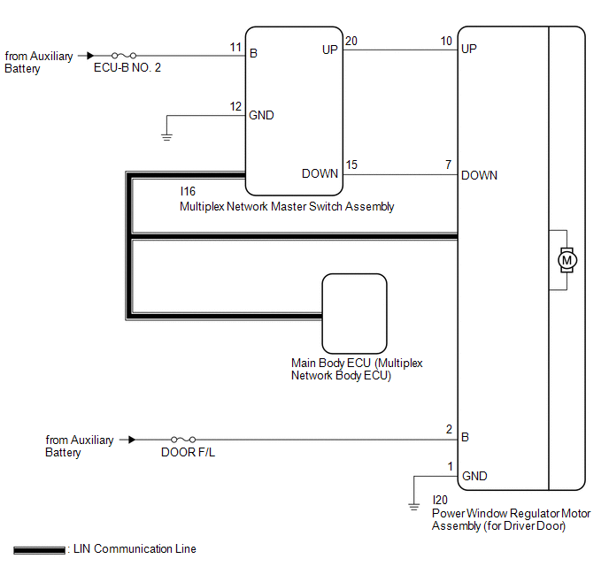
WIRING DIAGRAM
CAUTION / NOTICE / HINT
NOTICE:
Click here 
Click here
Click here
PROCEDURE
|
1. | READ VALUE USING TECHSTREAM (MAIN BODY) |
(a) Connect the Techstream to the DLC3.
(b) Turn the power switch on (IG).
(c) Turn the Techstream on.
(d) Enter the following menus: Body Electrical / Main Body / Data List.
(e) Read the Data List according to the display on the Techstream.
Body Electrical > Main Body > Data List|
Tester Display | Measurement Item |
Range | Normal Condition |
Diagnostic Note |
|---|---|---|---|---|
|
Communication D-Door Motor |
Connection status between power window regulator motor assembly (for driver door) and main body ECU (multiplex network body ECU) |
STOP or OK | STOP: Communication stopped OK: Normal communication |
- |
| Communication Master SW |
Connection status between multiplex network master switch assembly and main body ECU (multiplex network body ECU) |
STOP or OK | STOP: Communication stopped OK: Normal communication |
- |
|
Tester Display |
|---|
| Communication D-Door Motor |
|
Communication Master SW |
OK:
OK is displayed for each Data List item above.
| NG |  | GO TO LIN COMMUNICATION SYSTEM (Proceed to How to Proceed with Troubleshooting) |
|
| 2. |
READ VALUE USING TECHSTREAM (D-DOOR MOTOR) |
(a) Enter the following menus: Body Electrical / D-Door Motor / Data List.
(b) Read the Data List according to the display on the Techstream.
Body Electrical > D-Door Motor > Data List|
Tester Display | Measurement Item |
Range | Normal Condition |
Diagnostic Note |
|---|---|---|---|---|
|
D Door P/W Up SW | Driver door power window manual up switch signal |
OFF or ON | OFF: Driver door power window manual up switch not being operated ON: Driver door power window manual up switch being operated |
- |
| D Door P/W Down SW |
Driver door power window manual down switch signal |
OFF or ON | OFF: Driver door power window manual down switch not being operated ON: Driver door power window manual down switch being operated |
- |
|
Tester Display |
|---|
| D Door P/W Up SW |
|
D Door P/W Down SW |
OK:
On the Techstream screen, ON or OFF is displayed accordingly.
| NG | | GO TO STEP 4 |
|
| 3. |
PERFORM ACTIVE TEST USING TECHSTREAM (D-DOOR MOTOR) |
(a) Enter the following menus: Body Electrical / D-Door Motor / Active Test.
(b) Perform the Active Test according to the display on the Techstream.
CAUTION:
Be careful to avoid injuries as this test causes vehicle parts to move. During the Active Test, the jam protection function will not operate.
Body Electrical > D-Door Motor > Active Test|
Tester Display | Measurement Item |
Control Range | Diagnostic Note |
|---|---|---|---|
|
Power Window | Power window |
OFF / DOWN / UP | - |
|
Tester Display |
|---|
| Power Window |
OK:
Driver door power window operates normally.
| OK | | REPLACE MAIN BODY ECU (MULTIPLEX NETWORK BODY ECU) |
| NG | | REPLACE POWER WINDOW REGULATOR MOTOR ASSEMBLY (for Driver Door) |
| 4. |
CHECK HARNESS AND CONNECTOR (MULTIPLEX NETWORK MASTER SWITCH ASSEMBLY - POWER WINDOW REGULATOR MOTOR ASSEMBLY (for Driver Door)) |
(a) Disconnect the I16 multiplex network master switch assembly connector.
(b) Disconnect the I20 power window regulator motor assembly (for driver door) connector.
(c) Measure the resistance according to the value(s) in the table below.
Standard Resistance:
|
Tester Connection | Condition |
Specified Condition |
|---|---|---|
|
I16-20 (UP) - I20-10 (UP) |
Always | Below 1 Ω |
|
I16-20 (UP) or I20-10 (UP) - Body ground |
Always | 10 kΩ or higher |
|
I16-15 (DOWN) - I20-7 (DOWN) |
Always | Below 1 Ω |
|
I16-15 (DOWN) or I20-7 (DOWN) - Body ground |
Always | 10 kΩ or higher |
| NG | | REPAIR OR REPLACE HARNESS OR CONNECTOR |
|
| 5. |
INSPECT POWER WINDOW REGULATOR MOTOR ASSEMBLY (for Driver Door) |
(a) Remove the power window regulator motor assembly (for driver door).
Click here
(b) Inspect the power window regulator motor assembly (for driver door).
Click here
| OK | | REPLACE MULTIPLEX NETWORK MASTER SWITCH ASSEMBLY |
| NG | | REPLACE POWER WINDOW REGULATOR MOTOR ASSEMBLY (for Driver Door) |
DTC CHECK / CLEAR
CHECK DTC
(a) Connect the Techstream to the DLC3.
(b) Turn the power switch on (IG).
(c) Turn the Techstream on.
(d) Enter the following menus: Body Electrical / (desired system) / Trouble Codes.
Body Electrical > Master Switch > Trouble Codes Body Electrical > D-Door Motor > Trouble Codes Body Electrical > P-Door Motor > Trouble Codes Body Electrical > RL-Door Motor > Trouble Codes Body Electrical > RR-Door Motor > Trouble Codes(e) Check the details of the DTCs.
Click here 
CLEAR DTC
(a) Connect the Techstream to the DLC3.
(b) Turn the power switch on (IG).
(c) Turn the Techstream on.
(d) Enter the following menus: Body Electrical / (desired system) / Trouble Codes.
Body Electrical > Master Switch > Clear DTCs Body Electrical > D-Door Motor > Clear DTCs Body Electrical > P-Door Motor > Clear DTCs Body Electrical > RL-Door Motor > Clear DTCs Body Electrical > RR-Door Motor > Clear DTCs(e) Clear the DTCs.
FAIL-SAFE CHART
PULSE FAILURE
(a) If a pulse sensor built into the power window regulator motor assembly malfunctions, the following power window operations will be prohibited.
Multiplex Network Master Switch Assembly, Power Window Regulator Switch Assembly, Rear Power Window Regulator Switch Assembly (for RH and LH Doors)|
Power Window Operation |
Condition | ||
|---|---|---|---|
| Power switch on (IG) |
Power switch off (Key-off operation permitted) |
Power switch off (Key-off operation prohibited) | |
|
Manual up (Switch on the door) |
▲ | X |
- |
| Manual down (Switch on the door) |
● | X |
- |
| Auto up (Switch on the door) |
X | X |
- |
| Auto down (Switch on the door) |
X | X |
- |
| Manual up (Remote switch operation) |
X | X |
- |
| Manual down (Remote switch operation) |
X | X |
- |
| Auto up (Remote switch operation) |
X | X |
- |
| Auto down (Remote switch operation) |
X | X |
- |
| Key-linked open and close |
X | X |
X |
| Wireless transmitter-linked open and close |
X | X |
X |
HINT:
DISPLACEMENT OF NON-DETECTION RANGE TO THE OPENING DIRECTION
(a) If the door glass position or learned value is abnormal, the following power window operations will be prohibited.
Multiplex Network Master Switch Assembly, Power Window Regulator Switch Assembly, Rear Power Window Regulator Switch Assembly (for RH and LH Doors)|
Power Window Operation |
Condition | ||
|---|---|---|---|
| Power switch on (IG) |
Power switch off (Key-off operation permitted) |
Power switch off (Key-off operation prohibited) | |
|
Manual up (Switch on the door) |
● | X |
- |
| Manual down (Switch on the door) |
● | X |
- |
| Auto up (Switch on the door) |
X | X |
- |
| Auto down (Switch on the door) |
X | X |
- |
| Manual up (Remote switch operation) |
X | X |
- |
| Manual down (Remote switch operation) |
X | X |
- |
| Auto up (Remote switch operation) |
X | X |
- |
| Auto down (Remote switch operation) |
X | X |
- |
| Key-linked open and close |
X | X |
X |
| Wireless transmitter-linked open and close |
X | X |
X |
HINT:
INITIAL FAILURE
(a) During initialization, if the power window position or initialization complete status cannot be properly read from the non-volatile memory, the following power window operations will be prohibited.
Multiplex Network Master Switch Assembly, Power Window Regulator Switch Assembly, Rear Power Window Regulator Switch Assembly (for RH and LH Doors)|
Power Window Operation |
Condition | ||
|---|---|---|---|
| Power switch on (IG) |
Power switch off (Key-off operation permitted) |
Power switch off (Key-off operation prohibited) | |
|
Manual up (Switch on the door) |
● | X |
- |
| Manual down (Switch on the door) |
● | X |
- |
| Auto up (Switch on the door) |
X | X |
- |
| Auto down (Switch on the door) |
X | X |
- |
| Manual up (Remote switch operation) |
X | X |
- |
| Manual down (Remote switch operation) |
X | X |
- |
| Auto up (Remote switch operation) |
X | X |
- |
| Auto down (Remote switch operation) |
X | X |
- |
| Key-linked open and close |
X | X |
X |
| Wireless transmitter-linked open and close |
X | X |
X |
HINT:
Click here 
LIN COMMUNICATION FAILURE
(a) If the LIN communication system is malfunctioning (communication stop), the following power window control operations will be prohibited. (Operation is only possible using the power window switch of each seat.)
Multiplex Network Master Switch Assembly|
Power Window Operation | Condition |
|---|---|
|
Always | |
| Manual up |
●* |
| Manual down |
● |
| Auto up |
- |
| Auto down |
- |
|
Power Window Operation | Condition |
|---|---|
|
Always | |
| Manual up |
●* |
| Manual down |
● |
| Auto up |
●* |
| Auto down |
● |
HINT:
Click here
PULSE FAILURE AND LIN COMMUNICATION FAILURE
(a) If the LIN communication system is malfunctioning (communication stop) and the pulse sensor is malfunctioning, the following power window operations will be prohibited.
Multiplex Network Master Switch Assembly, Power Window Regulator Switch Assembly, Rear Power Window Regulator Switch Assembly (for RH and LH Doors)|
Power Window Operation | Condition |
|---|---|
|
Always | |
| Manual up |
X |
| Manual down |
X |
| Auto up |
X |
| Auto down |
X |
HINT:
When the jam protection function does not operate due to LIN communication failure, the manual up and auto up functions will not operate as the state of the IG signal is unknown.
Operation is not possible during LIN communication failure.
DISPLACEMENT OF NON-DETECTION RANGE TO THE OPENING DIRECTION AND LIN COMMUNICATION FAILURE / INITIAL FAILURE AND LIN COMMUNICATION FAILURE
(a) If the LIN communication system is malfunctioning and the power window position and learned value are abnormal, or the LIN communication system is malfunctioning and the power window position or initialization complete status cannot be properly read from the non-volatile memory during initialization, the following power window operations will be prohibited.
Multiplex Network Master Switch Assembly|
Power Window Operation | Condition |
|---|---|
|
Always | |
| Manual up |
●* |
| Manual down |
● |
| Auto up |
- |
| Auto down |
- |
|
Power Window Operation | Condition |
|---|---|
|
Always | |
| Manual up |
●* |
| Manual down |
● |
| Auto up |
X |
| Auto down |
X |
HINT:
Operation is not possible during LIN communication failure.
DESCRIPTION
When the power switch is on (IG), the power window regulator motor assembly (for front passenger door) is operated by the power window regulator switch assembly. The power window regulator motor assembly (for front passenger door) has motor, regulator, and ECU functions.
WIRING DIAGRAM
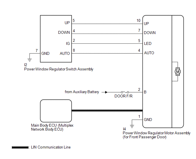
CAUTION / NOTICE / HINT
NOTICE:
Click here 
Click here
Click here
PROCEDURE
|
1. | READ VALUE USING TECHSTREAM (MAIN BODY) |
(a) Connect the Techstream to the DLC3.
(b) Turn the power switch on (IG).
(c) Turn the Techstream on.
(d) Enter the following menus: Body Electrical / Main Body / Data List.
(e) Read the Data List according to the display on the Techstream.
Body Electrical > Main Body > Data List|
Tester Display | Measurement Item |
Range | Normal Condition |
Diagnostic Note |
|---|---|---|---|---|
|
Communication P-Door Motor |
Connection status between power window regulator motor assembly (for front passenger door) and main body ECU (multiplex network body ECU) |
STOP or OK | STOP: Communication stopped OK: Normal communication |
- |
|
Tester Display |
|---|
| Communication P-Door Motor |
OK:
OK is displayed for each Data List item above.
| NG |  | GO TO LIN COMMUNICATION SYSTEM (Proceed to How to Proceed with Troubleshooting) |
|
| 2. |
READ VALUE USING TECHSTREAM (P-DOOR MOTOR) |
(a) Enter the following menus: Body Electrical / P-Door Motor / Data List.
(b) Read the Data List according to the display on the Techstream.
Body Electrical > P-Door Motor > Data List|
Tester Display | Measurement Item |
Range | Normal Condition |
Diagnostic Note |
|---|---|---|---|---|
|
P Door P/W Up SW | Front passenger door power window manual up switch signal |
OFF or ON | OFF: Front passenger door power window manual up switch not being operated ON: Front passenger door power window manual up switch being operated |
- |
| P Door P/W Down SW |
Front passenger door power window manual down switch signal |
OFF or ON | OFF: Front passenger door power window manual down switch not being operated ON: Front passenger door power window manual down switch being operated |
- |
|
Tester Display |
|---|
| P Door P/W Up SW |
|
P Door P/W Down SW |
OK:
On the Techstream screen, ON or OFF is displayed accordingly.
| NG | | GO TO STEP 4 |
|
| 3. |
PERFORM ACTIVE TEST USING TECHSTREAM (P-DOOR MOTOR) |
(a) Enter the following menus: Body Electrical / P-Door Motor / Active Test.
(b) Perform the Active Test according to the display on the Techstream.
CAUTION:
Be careful to avoid injuries as this test causes vehicle parts to move. During the Active Test, the jam protection function will not operate.
Body Electrical > P-Door Motor > Active Test|
Tester Display | Measurement Item |
Control Range | Diagnostic Note |
|---|---|---|---|
|
Power Window | Power window |
OFF / DOWN / UP | - |
|
Tester Display |
|---|
| Power Window |
OK:
Front passenger door power window operates normally.
| OK | | REPLACE MAIN BODY ECU (MULTIPLEX NETWORK BODY ECU) |
| NG | | REPLACE POWER WINDOW REGULATOR MOTOR ASSEMBLY (for Front Passenger Door) |
| 4. |
INSPECT POWER WINDOW REGULATOR SWITCH ASSEMBLY |
(a) Remove the power window regulator switch assembly.
Click here
(b) Inspect the power window regulator switch assembly.
Click here
| NG | | REPLACE POWER WINDOW REGULATOR SWITCH ASSEMBLY |
|
| 5. |
CHECK HARNESS AND CONNECTOR (POWER WINDOW REGULATOR SWITCH ASSEMBLY -POWER WINDOW REGULATOR MOTOR ASSEMBLY (FOR FRONT PASSENGER DOOR) AND BODY GROUND) |
(a) Disconnect the I4 power window regulator motor assembly (for front passenger door) connector.
(b) Measure the resistance according to the value(s) in the table below.
Standard Resistance:
|
Tester Connection | Condition |
Specified Condition |
|---|---|---|
|
I2-5 (UP) - I4-10 (UP) |
Always | Below 1 Ω |
|
I2-5 (UP) or I4-10 (UP) - Body ground |
Always | 10 kΩ or higher |
|
I2-4 (DOWN) - I4-7 (DOWN) |
Always | Below 1 Ω |
|
I2-4 (DOWN) or I4-7 (DOWN) - Body ground |
Always | 10 kΩ or higher |
|
I2-7 (GND) - Body ground |
Always | Below 1 Ω |
| OK | | REPLACE POWER WINDOW REGULATOR MOTOR ASSEMBLY (for Front Passenger Door) |
| NG | | REPAIR OR REPLACE HARNESS OR CONNECTOR |
CAUTION / NOTICE / HINT
HINT:
PROCEDURE
|
1. | VEHICLE BROUGHT TO WORKSHOP |
|
| 2. |
CUSTOMER PROBLEM ANALYSIS |
HINT:
|
What |
Vehicle model, system name |
|
When |
Date, time, occurrence frequency |
|
Where |
Road conditions |
|
Under what conditions? |
Driving conditions, weather conditions |
|
How did it happen? |
Problem symptoms |
|
| 3. |
PRE-CHECK |
(a) Measure the auxiliary battery voltage with the power switch off.
Standard Voltage:
11 to 14 V
If the voltage is below 11 V, recharge or replace the auxiliary battery before proceeding to the next step.
(b) Check the fuses and relays.
(c) Check the connector connections and terminals to make sure that there are no abnormalities such as loose connections, deformation, etc.
|
| 4. |
INSPECT COMMUNICATION FUNCTION OF CAN COMMUNICATION SYSTEM* |
(a) Using the Techstream, check for CAN communication system DTCs.
Click here

|
Result | Proceed to |
|---|---|
|
CAN DTCs are not output |
A |
| CAN DTCs are output |
B |
| B |
 | GO TO CAN COMMUNICATION SYSTEM |
|
| 5. |
INSPECT COMMUNICATION FUNCTION OF LIN COMMUNICATION SYSTEM* |
(a) Using the Techstream, check for LIN communication system DTCs.
Click here
|
Result | Proceed to |
|---|---|
|
LIN DTCs are not output |
A |
| LIN DTCs are output |
B |
| B |
| GO TO LIN COMMUNICATION SYSTEM |
|
| 6. |
CHECK FOR DTC* |
(a) Check for DTCs and make a note of any codes that are output.
Click here
(b) Clear the DTCs.
Body Electrical > Master Switch > Clear DTCs Body Electrical > D-Door Motor > Clear DTCs Body Electrical > P-Door Motor > Clear DTCs Body Electrical > RL-Door Motor > Clear DTCs Body Electrical > RR-Door Motor > Clear DTCs(c) Recheck for DTCs.
Body Electrical > Master Switch > Trouble Codes Body Electrical > D-Door Motor > Trouble Codes Body Electrical > P-Door Motor > Trouble Codes Body Electrical > RL-Door Motor > Trouble Codes Body Electrical > RR-Door Motor > Trouble Codes|
Result | Proceed to |
|---|---|
|
DTCs are not output | A |
|
DTCs are output | B |
| B |
| GO TO DIAGNOSTIC TROUBLE CODE CHART |
|
| 7. |
PROBLEM SYMPTOMS TABLE |
(a) Refer to Problem Symptoms Table.
Click here
|
Result | Proceed to |
|---|---|
|
Fault is not listed in problem symptoms table |
A |
| Fault is listed in problem symptoms table |
B |
| B |
| GO TO STEP 9 |
|
| 8. |
OVERALL ANALYSIS AND TROUBLESHOOTING* |
(a) Operation Check
Click here
(b) Terminals of ECU
Click here
(c) Data List / Active Test
Click here
(d) Fail-safe Chart
Click here
(e) Inspection
|
| 9. |
ADJUST, REPAIR OR REPLACE |
(a) Check if any of the door window regulator sub-assemblies, power window regulator motor assemblies, door glass or door glass runs have been removed and reinstalled.
|
Result | Proceed to |
|---|---|
|
Any of the door window regulator sub-assemblies, power window regulator motor assemblies, door glass or door glass runs have been removed and reinstalled. | A |
|
The door window regulator sub-assemblies, power window regulator motor assemblies, door glass and door glass runs have not been removed and reinstalled. | B |
| B |
| GO TO STEP 11 |
|
| 10. |
INITIALIZE POWER WINDOW CONTROL SYSTEM |
(a) If any of the door window regulator sub-assemblies, power window regulator motor assemblies, door glass or door glass runs have been removed and reinstalled, initialize the power window control system.
Click here
|
| 11. |
CONFIRMATION TEST |
| NEXT | | END |
INITIALIZATION
INITIALIZE POWER WINDOW CONTROL SYSTEM (ALL DOORS)
NOTICE:
Click here 
Click here
HINT:
If the auxiliary battery has been replaced, it is not necessary to initialize the power window regulator motor assemblies.
(a) Perform initialization according to the table below.
|
Condition of Power Window |
Proceed to |
|---|---|
| A power window regulator motor assembly has been replaced with a new one. |
Procedure A |
HINT: Use this procedure if a power window regulator motor assembly is being reused. |
Procedure B |
| Power window unexpectedly operates in reverse or stops due to a change in the sliding resistance after a fitting adjustment is made. |
Procedure C |
(b) Procedure A
(1) Perform window position initialization (fully closed, fully open) and sliding resistance learning.
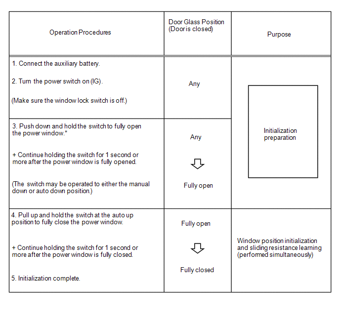
HINT:
*: Even if the door glass is in the fully open position before performing step 3, push down and hold the switch for 1 second or more.
(c) Procedure B
(1) Perform window position initialization (fully closed, fully open) and sliding resistance learning.
Reset the power window position, perform window position initialization (fully closed, fully opened) and sliding resistance learning.
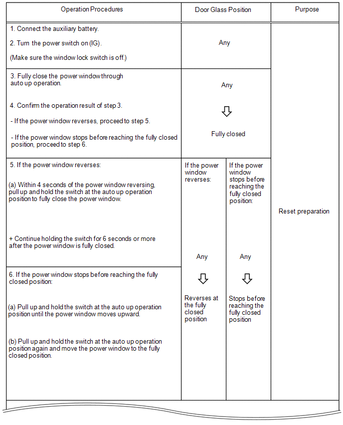
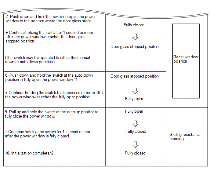
HINT:
If initialization cannot be completed properly, the LIN communication system may be malfunctioning.
Click here
(d) Procedure C
(1) Perform sliding resistance learning.
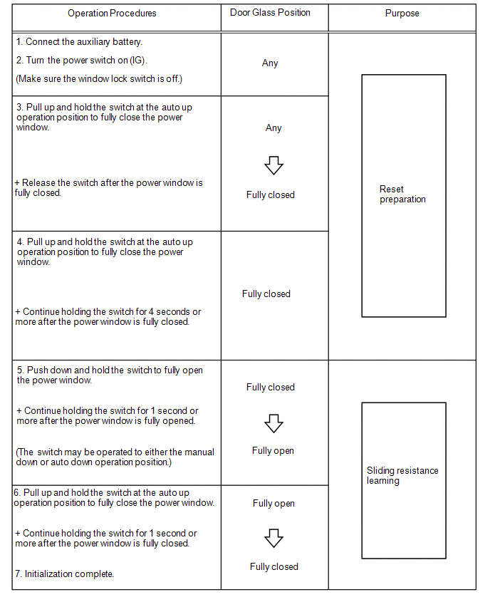
HINT:
If the jam protection function or catch protection function continues to operate even after performing steps 4, 5 and 6, perform the procedure again from step 3.
DESCRIPTION
This symptom may occur for any of the power windows.
The jam protection function operates within a specified range during the manual up or auto up operation.
CAUTION / NOTICE / HINT
NOTICE:
Click here 
Click here
PROCEDURE
|
1. | PERFORM INITIALIZATION (APPLICABLE LOCATION) |
(a) Initialize the power window regulator motor assembly (applicable location).
Click here
|
| 2. |
CHECK POWER WINDOW CONTROL SYSTEM (AUTO UP / DOWN FUNCTION) |
(a) Check if the power window auto up and down functions operate normally.
Click here
OK:
Auto up and down functions are normal.
| NG |  | GO TO OTHER PROBLEM (Proceed to Problem Symptoms Table) |
|
| 3. |
CHECK JAM PROTECTION FUNCTION OPERATING RANGE |
(a) Check if the jam protection function operates normally for the applicable power window.
HINT:
The jam protection function will not operate within 4 mm (0.157 in.) of the fully closed position.
OK:
Jam protection function operates normally.
|
Result | Proceed to |
|---|---|
|
OK | A |
|
NG (Driver door power window) |
B |
| NG (Front passenger door power window) | |
|
NG (Rear LH door power window) |
C |
| NG (Rear RH door power window) |
| A |
| END (PROBLEM DUE TO INITIALIZATION FAILURE) |
| B |
| REPLACE POWER WINDOW REGULATOR MOTOR ASSEMBLY (for Driver Door or Front Passenger Door) |
| C |
| REPLACE POWER WINDOW REGULATOR MOTOR ASSEMBLY (for Rear LH Door or Rear RH Door) |
DESCRIPTION
When the front doors are closed, each power window regulator motor assembly can be operated for approximately 45 seconds after the power switch is turned from on (IG) to off by receiving operation permission signals from the main body ECU (multiplex network body ECU). However, when approximately 45 seconds have elapsed, or the driver door or front passenger door is opened within approximately 45 seconds of the power switch being turned off, the power window regulator motor assemblies stop operating.
During auto operation, when 45 seconds have elapsed and key-off operation is prohibited, the power window stops immediately.
CAUTION / NOTICE / HINT
NOTICE:
Click here 
Click here
Click here
PROCEDURE
|
1. | CHECK MANUAL UP / DOWN FUNCTION |
(a) Check that the manual up and down functions using the multiplex network master switch assembly, power window regulator switch assembly and rear power window regulator switch assembly (for LH or RH door) can operate the power windows.
Click here
OK:
Manual up and down functions are normal.
| NG |  | GO TO OTHER PROBLEM (Proceed to Problem Symptoms Table) |
|
| 2. |
CHECK REMOTE UP / DOWN FUNCTION |
(a) Check that the remote up and down functions using the multiplex network master switch assembly can operate all of the power windows.
Click here
OK:
Remote up and down functions are normal.
| NG | | GO TO OTHER PROBLEM (Proceed to Problem Symptoms Table) |
|
| 3. |
CHECK KEY-OFF OPERATION FUNCTION |
(a) Check the key-off operation function.
Click here
|
Result | Proceed to |
|---|---|
|
Power window can be operated even after opening driver door or front passenger door within approximately 45 seconds of power switch being turned off | A |
|
Power window can be operated even after approximately 45 seconds have elapsed since power switch was turned off (for All Doors) |
B |
| Power window can be operated even after approximately 45 seconds have elapsed since power switch was turned off (for Driver Door or Front Passenger Door) | C |
|
Power window can be operated even after approximately 45 seconds have elapsed since power switch was turned off (for Rear LH Door or Rear RH Door) |
D |
| B |
| REPLACE MAIN BODY ECU (MULTIPLEX NETWORK BODY ECU) |
| C |
| REPLACE POWER WINDOW REGULATOR MOTOR ASSEMBLY (for Driver Door or Front Passenger Door) |
| D |
| REPLACE POWER WINDOW REGULATOR MOTOR ASSEMBLY (for Rear LH Door or Rear RH Door) |
|
| 4. |
READ VALUE USING TECHSTREAM (MAIN BODY) |
(a) Connect the Techstream to the DLC3.
(b) Turn the power switch on (IG).
(c) Turn the Techstream on.
(d) Enter the following menus: Body Electrical / Main Body / Data List.
(e) Read the Data List according to the display on the Techstream.
Body Electrical > Main Body > Data List|
Tester Display | Measurement Item |
Range | Normal Condition |
Diagnostic Note |
|---|---|---|---|---|
|
FR Door Courtesy SW | Front door courtesy light switch assembly (for RH) signal |
OFF or ON | OFF: Front door RH closed ON: Front door RH open |
- |
| FL Door Courtesy SW |
Front door courtesy light switch assembly (for LH) signal |
OFF or ON | OFF: Front door LH closed ON: Front door LH open |
- |
|
Tester Display |
|---|
| FR Door Courtesy SW |
|
FL Door Courtesy SW |
OK:
On the Techstream screen, ON or OFF is displayed accordingly.
| OK | | REPLACE MAIN BODY ECU (MULTIPLEX NETWORK BODY ECU) |
| NG | | GO TO LIGHTING SYSTEM (Proceed to Front Door Courtesy Switch Circuit) |
OPERATION CHECK
CHECK WINDOW LOCK FUNCTION
HINT:
Before performing the window lock switch operation check, make sure that the window lock switch is off (the switch is not pushed in).
(a) Turn the window lock switch of the multiplex network master switch assembly on (pushed in) and check that the front passenger and rear windows are disabled.
OK:
Front passenger and rear windows are disabled.
(b) Turn the window lock switch off (not pushed in) and check that the front passenger and rear windows can be operated normally.
OK:
Front passenger and rear windows operate normally.
CHECK MANUAL UP / DOWN FUNCTION
(a) Check that the driver door power window operates as follows:
OK|
Condition | Master Switch |
Switch Operation | Power Window |
|---|---|---|---|
|
Power switch on (IG) | Driver door |
Pulled halfway up | UP (Closes) |
|
Pushed halfway down | DOWN (Opens) |
(b) Check that the front passenger door power window and rear door power windows operate as follows:
OK|
Condition | Regulator Switch |
Switch Operation | Power Window |
|---|---|---|---|
| Front passenger door |
Pulled halfway up | UP (Closes) |
|
Pushed halfway down | DOWN (Opens) | ||
|
Rear LH door | Pulled halfway up |
UP (Closes) | |
| Pushed halfway down |
DOWN (Opens) | ||
|
Rear RH door | Pulled halfway up |
UP (Closes) | |
| Pushed halfway down |
DOWN (Opens) |
CHECK AUTO UP / DOWN FUNCTION
(a) Check that the driver door power window operates as follows:
OK|
Condition | Master Switch |
Switch Operation | Power Window |
|---|---|---|---|
|
Power switch on (IG) | Driver door |
Pulled up (One touch operation) | AUTO UP (Closes) |
|
Pushed down (One touch operation) | AUTO DOWN (Opens) |
(b) Check that the front passenger door power window and rear door power windows operate as follows:
OK|
Condition | Regulator Switch |
Switch Operation | Power Window |
|---|---|---|---|
| Front passenger door |
Pulled up (One touch operation) | AUTO UP (Closes) |
|
Pushed down (One touch operation) | AUTO DOWN (Opens) | ||
|
Rear LH door | Pulled up (One touch operation) |
AUTO UP (Closes) | |
| Pushed down (One touch operation) |
AUTO DOWN (Opens) | ||
|
Rear RH door | Pulled up (One touch operation) |
AUTO UP (Closes) | |
| Pushed down (One touch operation) |
AUTO DOWN (Opens) |
CHECK REMOTE MANUAL UP / DOWN FUNCTION
(a) Check that the front passenger door power window and rear door power windows operate as follows:
OK|
Condition | Master Switch |
Switch Operation | Power Window |
|---|---|---|---|
| Front passenger door |
Pulled halfway up | UP (Closes) |
|
Pushed halfway down | DOWN (Opens) | ||
|
Rear LH door | Pulled halfway up |
UP (Closes) | |
| Pushed halfway down |
DOWN (Opens) | ||
|
Rear RH door | Pulled halfway up |
UP (Closes) | |
| Pushed halfway down |
DOWN (Opens) |
CHECK REMOTE AUTO UP / DOWN FUNCTION
(a) Check that the front passenger door power window and rear door power windows operate as follows:
OK|
Condition | Master Switch |
Switch Operation | Power Window |
|---|---|---|---|
| Front passenger door |
Pulled up (One touch operation) | AUTO UP (Closes) |
|
Pushed down (One touch operation) | AUTO DOWN (Opens) | ||
|
Rear LH door | Pulled up (One touch operation) |
AUTO UP (Closes) | |
| Pushed down (One touch operation) |
AUTO DOWN (Opens) | ||
|
Rear RH door | Pulled up (One touch operation) |
AUTO UP (Closes) | |
| Pushed down (One touch operation) |
AUTO DOWN (Opens) |
CHECK KEY-OFF OPERATION FUNCTION
(a) Check that each power window can be operated with the multiplex network master switch assembly, power window regulator switch assembly or rear power window regulator switch assembly after the power switch is turned off.
HINT:
If the window lock switch is on, the power windows cannot be operated using the power window regulator switch assembly and rear power window regulator switch assemblies. Therefore, turn the window lock switch off before checking the power window operation.
(b) Check that the key-off operation function does not operate immediately after the driver door or front passenger door is opened.
HINT:
(c) Check that all of the power windows cannot be operated after more than approximately 45 seconds have elapsed since the power switch is turned off.
CHECK WIRELESS TRANSMITTER-LINKED FUNCTION*
(a) Check that all of the power windows operate as follows when operating the key:
OK|
Condition | Transmitter Operation |
Power Window |
|---|---|---|
| No key is inside vehicle, and all doors are closed and locked |
UNLOCK switch pressed for more than 3 seconds |
DOWN (Opens) |
| No key is inside vehicle, and all doors are closed and locked |
UNLOCK switch released |
STOP |
CHECK KEY-LINKED FUNCTION*
(a) Check that all of the power windows operate as follows:
OK|
Condition | Door Key Cylinder Operation |
Power Window |
|---|---|---|
| No key is inside vehicle, and all doors are closed |
Turned to the lock position and held for more than 1.5 seconds |
UP (Closes) |
| No Key is inside vehicle, and all doors are closed |
Returned to neutral position |
STOP |
| No Key is inside vehicle, and all doors are closed |
Turned to the unlock position and held for more than 1.5 seconds |
DOWN (Opens) |
| No Key is inside vehicle, and all doors are closed |
Returned to neutral position |
STOP |
CHECK WINDOW OPEN WARNING FUNCTION
(a) Open a window using the power window switch.
(b) Turn the power switch from on (IG) to off, open the driver door with the Key in the vehicle and check that the warning buzzer in the combination meter assembly sounds once. Then, check that message is displayed on the multi-information display in the combination meter assembly.
CHECK JAM PROTECTION FUNCTION
(a) Check the basic function.
CAUTION:
Do not put your fingers between the door frame and door glass to check the jam protection function. Also, prevent any part of your body from being caught during inspection.
HINT:
The jam protection function is operative during both the auto up and manual up operations while the hybrid control system is started or the power switch is on (IG), and also for approximately 45 seconds after the power switch is turned off.
(1) Fully open the power window.
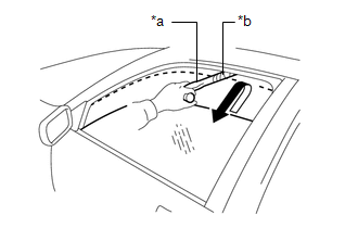
|
*a | Check Jig |
|
*b | Cloth |
(2) Set a check jig wrapped with a piece of cloth near the power window fully closed position.
(3) Operate the auto up or manual up function and check that the power window stops and goes down after the check jig is caught between the door glass and door frame, and stops.
HINT:
(4) While the power window is moving down, check that the door glass cannot be raised using the power window switch.
CHECK CATCH PROTECTION FUNCTION
(a) Check the basic function.
CAUTION:
Do not put your fingers between the door frame and door glass to check the jam protection function. Also, prevent any part of your body from being caught during inspection.
HINT:
The catch protection function is operative during both the auto down and manual down operations while the hybrid control system is started or the power switch is on (IG), and also for approximately 45 seconds after the power switch is turned off.
(1) Fully close all of the power windows.
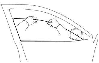
(2) Operate the auto down or manual down function to open the power window, grasp the upper edge of the door glass with one or two hands and check that the power window stops.
HINT:
After the catch protection function has operated when an auto down or manual down operation was performed, the catch protection function will not operate if the manual down operation is performed again within approximately 4 seconds.
CHECK POWER WINDOW SWITCH LED ILLUMINATION
(a) Check the LED illumination (multiplex network master switch assembly).
(1) Check that the LEDs located in the multiplex network master switch assembly illuminate when the headlight dimmer switch is in the tail position.
(b) Check the LED illumination (power window regulator switch assembly).
(1) Check that the LED located in the power window regulator switch assembly illuminates when the headlight dimmer switch is in the tail position.
(c) Check the LED illumination (rear power window regulator switch assembly).
(1) Check that the LED located in each rear power window regulator switch assembly illuminates when the headlight dimmer switch is in the tail position.
PARTS LOCATION
ILLUSTRATION
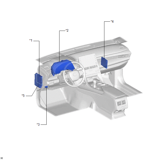
|
*1 | MAIN BODY ECU (MULTIPLEX NETWORK BODY ECU) |
*2 | COMBINATION METER ASSEMBLY |
|
*3 | DLC3 |
*4 | CERTIFICATION ECU (SMART KEY ECU ASSEMBLY) |
|
*5 | INSTRUMENT PANEL JUNCTION BLOCK ASSEMBLY - ECU-B NO. 2 FUSE - DOOR F/L FUSE - DOOR F/R FUSE - DOOR R/L FUSE - DOOR R/R FUSE |
- | - |
ILLUSTRATION
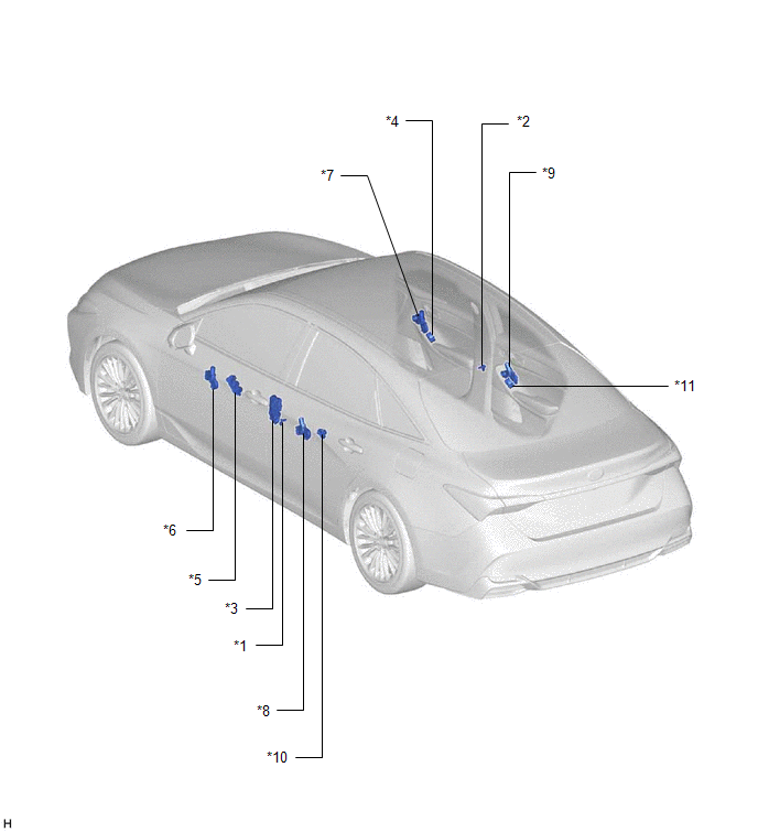
|
*1 | FRONT DOOR COURTESY LIGHT SWITCH ASSEMBLY (for LH) |
*2 | FRONT DOOR COURTESY LIGHT SWITCH ASSEMBLY (for RH) |
|
*3 | FRONT DOOR LOCK WITH MOTOR ASSEMBLY LH |
*4 | POWER WINDOW REGULATOR SWITCH ASSEMBLY |
|
*5 | MULTIPLEX NETWORK MASTER SWITCH ASSEMBLY |
*6 | POWER WINDOW REGULATOR MOTOR ASSEMBLY (for Driver Door) |
|
*7 | POWER WINDOW REGULATOR MOTOR ASSEMBLY (for Front Passenger Door) |
*8 | POWER WINDOW REGULATOR MOTOR ASSEMBLY (for Rear LH Door) |
|
*9 | POWER WINDOW REGULATOR MOTOR ASSEMBLY (for Rear RH Door) |
*10 | REAR POWER WINDOW REGULATOR SWITCH ASSEMBLY (for LH Door) |
|
*11 | REAR POWER WINDOW REGULATOR SWITCH ASSEMBLY (for RH Door) |
- | - |
PRECAUTION
PRECAUTION FOR DISCONNECTING CABLE FROM NEGATIVE AUXILIARY BATTERY TERMINAL
NOTICE:
When disconnecting the cable from the negative (-) auxiliary battery terminal, initialize the following systems after the cable is reconnected.
|
System Name | See Procedure |
|---|---|
|
Lane Departure Alert System (w/ Steering Control) |
|
|
Intelligent Clearance Sonar System | |
|
Parking Assist Monitor System | |
|
Panoramic View Monitor System | |
|
Pre-collision System | |
|
Lighting System (for HV Model with Cornering Light) |
POWER WINDOW CONTROL SYSTEM PRECAUTIONS
NOTICE:
Click here 
Click here
Click here
Click here
PROBLEM SYMPTOMS TABLE
NOTICE:
Click here 
HINT:
|
Symptom | Suspected Area |
Link |
|---|---|---|
|
Remote up / down function does not operate |
LIN communication system |
|
|
Multiplex network master switch assembly | ||
|
Power window regulator motor assembly (for front passenger door) | ||
|
Power window regulator motor assembly (for rear LH door) | ||
|
Power window regulator motor assembly (for rear RH door) | ||
|
Driver side power window does not operate with power window master switch |
LIN communication system |
|
|
Power window regulator motor assembly (for driver door) | ||
|
Multiplex network master switch assembly | ||
|
Main body ECU (Multiplex network body ECU) | ||
|
Wire harness or connector | ||
|
Front passenger side power window does not operate with front passenger side power window switch |
LIN communication system |
|
|
Power window regulator motor assembly (for front passenger door) | ||
|
Power window regulator switch assembly | ||
|
Main body ECU (Multiplex network body ECU) | ||
|
Wire harness or connector | ||
|
Rear power window LH does not operate with rear power window switch LH |
LIN communication system |
|
|
Power window regulator motor assembly (for rear LH door) | ||
|
Rear power window regulator switch assembly (for LH door) | ||
|
Main body ECU (Multiplex network body ECU) | ||
|
Wire harness or connector | ||
|
Rear power window RH does not operate with rear power window switch RH |
LIN communication system |
|
|
Power window regulator motor assembly (for rear RH door) | ||
|
Rear power window regulator switch assembly (for RH door) | ||
|
Main body ECU (Multiplex network body ECU) | ||
|
Wire harness or connector | ||
|
Driver side power window auto up / down function does not operate with power window master switch |
LIN communication system |
|
|
Power window regulator motor assembly (for driver door) | ||
|
Multiplex network master switch assembly | ||
|
Power window position initialization | ||
|
Wire harness or connector | ||
|
Front passenger side power window auto up / down function does not operate with front passenger side power window switch |
Power window regulator motor assembly (for front passenger door) |
|
|
Power window regulator switch assembly | ||
|
Power window position initialization | ||
|
Wire harness or connector | ||
|
Rear power window LH auto up / down function does not operate with rear power window switch LH |
Power window regulator motor assembly (for rear LH door) |
|
|
Rear power window regulator switch assembly (for LH door) | ||
|
Power window position initialization | ||
|
Wire harness or connector | ||
|
Rear power window RH auto up / down function does not operate with rear power window switch RH |
Power window regulator motor assembly (for rear RH door) |
|
|
Rear power window regulator switch assembly (for RH door) | ||
|
Power window position initialization | ||
|
Wire harness or connector | ||
|
All power windows do not operate with driver side door key cylinder or wireless transmitter |
LIN communication system |
|
| Wireless door lock control system | ||
|
Power door lock control system | ||
| Main body ECU (Multiplex network body ECU) | ||
|
Key-off operation function operates even if operating conditions are not satisfied |
LIN communication system |
|
|
Lighting system | ||
|
Power window regulator motor assembly (for driver door) | ||
|
Power window regulator motor assembly (for front passenger door) | ||
|
Power window regulator motor assembly (for rear LH door) | ||
|
Power window regulator motor assembly (for rear RH door) | ||
|
Main body ECU (Multiplex network body ECU) | ||
|
Auto up operation does not fully close power window (jam protection function is activated) |
Power window position initialization (applicable location) |
|
|
Improper installation (applicable location) | ||
|
Power window regulator motor assembly (for driver door) | ||
|
Power window regulator motor assembly (for front passenger door) | ||
|
Power window regulator motor assembly (for rear LH door) | ||
|
Power window regulator motor assembly (for rear RH door) | ||
|
Auto down operation does not fully open power window (catch protection function is activated) |
Power window position initialization (applicable location) |
|
|
Improper installation (applicable location) | ||
|
Power window regulator motor assembly (for driver door) | ||
|
Power window regulator motor assembly (for front passenger door) | ||
|
Power window regulator motor assembly (for rear LH door) | ||
|
Power window regulator motor assembly (for rear RH door) | ||
|
Jam protection function does not operate |
Power window position initialization (applicable location) |
|
|
Power window regulator motor assembly (for driver door) | ||
|
Power window regulator motor assembly (for front passenger door) | ||
|
Power window regulator motor assembly (for rear LH door) | ||
|
Power window regulator motor assembly (for rear RH door) | ||
|
Power windows do not operate using all window switch |
Main body ECU (Multiplex network body ECU) |
|
DESCRIPTION
If the manual up and down functions operate normally but the auto up and down functions do not, the power window control system may be in fail-safe mode.
If power window initialization has not been performed, the auto up and down functions will not operate.
Click here 
WIRING DIAGRAM
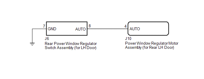
CAUTION / NOTICE / HINT
NOTICE:
Click here
Click here
HINT:
If the pulse sensor built into the power window regulator motor assembly (for rear LH door) is malfunctioning, the power window control system will enter fail-safe mode. The remote up and down and auto up and down functions cannot be operated during fail-safe mode. However, the power window can be closed by holding the rear power window regulator switch assembly (for LH door) at the auto up position, and opened manually by pushing down the rear power window regulator switch assembly (for LH door).
Click here
PROCEDURE
| 1. |
READ VALUE USING TECHSTREAM (RL-DOOR MOTOR) |
(a) Connect the Techstream to the DLC3.
(b) Turn the power switch on (IG).
(c) Turn the Techstream on.
(d) Enter the following menus: Body Electrical / RL-Door Motor / Data List.
(e) Read the Data List according to the display on the Techstream.
Body Electrical > RL-Door Motor > Data List|
Tester Display | Measurement Item |
Range | Normal Condition |
Diagnostic Note |
|---|---|---|---|---|
|
RL Door P/W Auto SW | Rear LH door power window auto switch signal |
OFF or ON | OFF: Rear LH door power window auto up or auto down switch not being operated ON: Rear LH door power window auto up or auto down switch being operated |
- |
|
Tester Display |
|---|
| RL Door P/W Auto SW |
OK:
On the Techstream screen, ON or OFF is displayed accordingly.
| NG |  | GO TO STEP 4 |
|
| 2. |
PERFORM INITIALIZATION (for Rear LH Door) |
(a) Initialize the power window regulator motor assembly (for rear LH door).
Click here
|
| 3. |
CHECK POWER WINDOW CONTROL SYSTEM (AUTO UP / DOWN FUNCTION) |
(a) Check that the rear LH door power window moves when the auto up and down functions of the rear power window regulator switch assembly (for LH door) are operated.
Click here
OK:
Rear LH door auto up and down functions are normal.
| OK | | END (PROBLEM DUE TO INITIALIZATION FAILURE) |
| NG | | REPLACE POWER WINDOW REGULATOR MOTOR ASSEMBLY (for Rear LH Door) |
| 4. |
INSPECT REAR POWER WINDOW REGULATOR SWITCH ASSEMBLY (for LH Door) |
(a) Remove the rear power window regulator switch assembly (for LH door).
Click here
(b) Inspect the rear power window regulator switch assembly (for LH door).
Click here
| NG | | REPLACE REAR POWER WINDOW REGULATOR SWITCH ASSEMBLY (for LH Door) |
|
| 5. |
CHECK HARNESS AND CONNECTOR (REAR POWER WINDOW REGULATOR SWITCH ASSEMBLY (for LH Door) - POWER WINDOW REGULATOR MOTOR ASSEMBLY (for Rear LH Door)) |
(a) Disconnect the J10 power window regulator motor assembly (for rear LH door) connector.
(b) Measure the resistance according to the value(s) in the table below.
Standard Resistance:
|
Tester Connection | Condition |
Specified Condition |
|---|---|---|
|
J6-8 (AUTO) - J10-4 (AUTO) |
Always | Below 1 Ω |
|
J6-8 (AUTO) or J10-4 (AUTO) - Body ground |
Always | 10 kΩ or higher |
| OK | | REPLACE POWER WINDOW REGULATOR MOTOR ASSEMBLY (for Rear LH Door) |
| NG | | REPAIR OR REPLACE HARNESS OR CONNECTOR |
DESCRIPTION
When the power switch is on (IG), the power window regulator motor assembly (for rear LH door) is operated by the rear power window regulator switch assembly (for LH door). The power window regulator motor assembly (for rear LH door) has motor, regulator, and ECU functions.
WIRING DIAGRAM

CAUTION / NOTICE / HINT
NOTICE:
Click here 
Click here
Click here
PROCEDURE
|
1. | READ VALUE USING TECHSTREAM (MAIN BODY) |
(a) Connect the Techstream to the DLC3.
(b) Turn the power switch on (IG).
(c) Turn the Techstream on.
(d) Enter the following menus: Body Electrical / Main Body / Data List.
(e) Read the Data List according to the display on the Techstream.
Body Electrical > Main Body > Data List|
Tester Display | Measurement Item |
Range | Normal Condition |
Diagnostic Note |
|---|---|---|---|---|
|
Communication RL-Door Motor |
Connection status between power window regulator motor assembly (for rear LH door) and main body ECU (multiplex network body ECU) |
STOP or OK | STOP: Communication stopped OK: Normal communication |
- |
|
Tester Display |
|---|
| Communication RL-Door Motor |
OK:
OK is displayed for each Data List item above.
| NG |  | GO TO LIN COMMUNICATION SYSTEM (Proceed to How to Proceed with Troubleshooting) |
|
| 2. |
READ VALUE USING TECHSTREAM (RL-DOOR MOTOR) |
(a) Enter the following menus: Body Electrical / RL-Door Motor / Data List.
(b) Read the Data List according to the display on the Techstream.
Body Electrical > RL-Door Motor > Data List|
Tester Display | Measurement Item |
Range | Normal Condition |
Diagnostic Note |
|---|---|---|---|---|
|
RL Door P/W Up SW | Rear LH door power window manual up switch signal |
OFF or ON | OFF: Rear LH door power window manual up switch not being operated ON: Rear LH door power window manual up switch being operated |
- |
| RL Door P/W Down SW |
Rear LH door power window manual down switch signal |
OFF or ON | OFF: Rear LH door power window manual down switch not being operated ON: Rear LH door power window manual down switch being operated |
- |
|
Tester Display |
|---|
| RL Door P/W Up SW |
|
RL Door P/W Down SW |
OK:
On the Techstream screen, ON or OFF is displayed accordingly.
| NG | | GO TO STEP 4 |
|
| 3. |
PERFORM ACTIVE TEST USING TECHSTREAM (RL-DOOR MOTOR) |
(a) Enter the following menus: Body Electrical / RL-Door Motor / Active Test.
(b) Perform the Active Test according to the display on the Techstream.
CAUTION:
Be careful to avoid injuries as this test causes vehicle parts to move. During the Active Test, the jam protection function will not operate.
Body Electrical > RL-Door Motor > Active Test|
Tester Display | Measurement Item |
Control Range | Diagnostic Note |
|---|---|---|---|
|
Power Window | Power window |
OFF / DOWN / UP | - |
|
Tester Display |
|---|
| Power Window |
OK:
Rear LH door power window operates normally.
| OK | | REPLACE MAIN BODY ECU (MULTIPLEX NETWORK BODY ECU) |
| NG | | REPLACE POWER WINDOW REGULATOR MOTOR ASSEMBLY (for Rear LH Door) |
| 4. |
INSPECT REAR POWER WINDOW REGULATOR SWITCH ASSEMBLY (for LH Door) |
(a) Remove the rear power window regulator switch assembly (for LH door).
Click here
(b) Inspect the rear power window regulator switch assembly (for LH door).
Click here
| NG | | REPLACE REAR POWER WINDOW REGULATOR SWITCH ASSEMBLY (for LH Door) |
|
| 5. |
CHECK HARNESS AND CONNECTOR (REAR POWER WINDOW REGULATOR SWITCH (for LH Door) - POWER WINDOW REGULATOR MOTOR (for Rear LH Door) AND BODY GROUND) |
(a) Disconnect the J10 power window regulator motor assembly (for rear LH door) connector.
(b) Measure the resistance according to the value(s) in the table below.
Standard Resistance:
|
Tester Connection | Condition |
Specified Condition |
|---|---|---|
|
J6-5 (UP) - J10-10 (UP) |
Always | Below 1 Ω |
|
J6-5 (UP) or J10-10 (UP) - Body ground |
Always | 10 kΩ or higher |
|
J6-4 (DOWN) - J10-7 (DOWN) |
Always | Below 1 Ω |
|
J6-4 (DOWN) or J10-7 (DOWN) - Body ground |
Always | 10 kΩ or higher |
|
J6-7 (GND) - Body ground |
Always | Below 1 Ω |
| OK | | REPLACE POWER WINDOW REGULATOR MOTOR ASSEMBLY (for Rear LH Door) |
| NG | | REPAIR OR REPLACE HARNESS OR CONNECTOR |
DESCRIPTION
If the manual up and down functions operate normally but the auto up and down functions do not, the power window control system may be in fail-safe mode.
If power window initialization has not been performed, the auto up and down functions will not operate.
Click here 
WIRING DIAGRAM
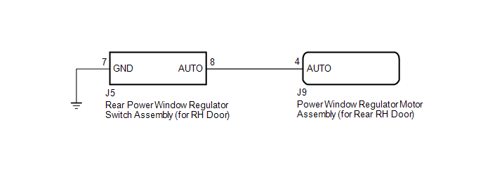
CAUTION / NOTICE / HINT
NOTICE:
Click here
Click here
HINT:
If the pulse sensor built into the power window regulator motor assembly (for rear RH door) is malfunctioning, the power window control system will enter fail-safe mode. The remote up and down and auto up and down functions cannot be operated during fail-safe mode. However, the power window can be closed by holding the rear power window regulator switch assembly (for RH door) at the auto up position, and opened manually by pushing down the rear power window regulator switch assembly (for RH door).
Click here
PROCEDURE
| 1. |
READ VALUE USING TECHSTREAM (RR-DOOR MOTOR) |
(a) Connect the Techstream to the DLC3.
(b) Turn the power switch on (IG).
(c) Turn the Techstream on.
(d) Enter the following menus: Body Electrical / RR-Door Motor / Data List.
(e) Read the Data List according to the display on the Techstream.
Body Electrical > RR-Door Motor > Data List|
Tester Display | Measurement Item |
Range | Normal Condition |
Diagnostic Note |
|---|---|---|---|---|
|
RR Door P/W Auto SW | Rear RH door power window auto switch signal |
OFF or ON | OFF: Rear RH door power window auto up or auto down switch not being operated ON: Rear RH door power window auto up or auto down switch being operated |
- |
|
Tester Display |
|---|
| RR Door P/W Auto SW |
OK:
On the Techstream screen, ON or OFF is displayed accordingly.
| NG |  | GO TO STEP 4 |
|
| 2. |
PERFORM INITIALIZATION (for Rear RH Door) |
(a) Initialize the power window regulator motor assembly (for rear RH door).
Click here
|
| 3. |
CHECK POWER WINDOW CONTROL SYSTEM (AUTO UP / DOWN FUNCTION) |
(a) Check that the rear RH door power window moves when the auto up and down functions of the rear power window regulator switch assembly (for RH door) are operated.
Click here
OK:
Rear RH door auto up and down functions are normal.
| OK | | END (PROBLEM DUE TO INITIALIZATION FAILURE) |
| NG | | REPLACE POWER WINDOW REGULATOR MOTOR ASSEMBLY (for Rear RH Door) |
| 4. |
INSPECT REAR POWER WINDOW REGULATOR SWITCH ASSEMBLY (for RH Door) |
(a) Remove the rear power window regulator switch assembly (for RH door).
Click here
(b) Inspect the rear power window regulator switch assembly (for RH door).
Click here
| NG | | REPLACE REAR POWER WINDOW REGULATOR SWITCH ASSEMBLY (for RH Door) |
|
| 5. |
CHECK HARNESS AND CONNECTOR (REAR POWER WINDOW REGULATOR SWITCH ASSEMBLY (for RH Door) - POWER WINDOW REGULATOR MOTOR ASSEMBLY (for Rear RH Door)) |
(a) Disconnect the J9 power window regulator motor assembly (for rear RH door) connector.
(b) Measure the resistance according to the value(s) in the table below.
Standard Resistance:
|
Tester Connection | Condition |
Specified Condition |
|---|---|---|
|
J5-8 (AUTO) - J9-4 (AUTO) |
Always | Below 1 Ω |
|
J5-8 (AUTO) or J9-4 (AUTO) - Body ground |
Always | 10 kΩ or higher |
| OK | | REPLACE POWER WINDOW REGULATOR MOTOR ASSEMBLY (for Rear RH Door) |
| NG | | REPAIR OR REPLACE HARNESS OR CONNECTOR |
DESCRIPTION
When the power switch is on (IG), the power window regulator motor assembly (for rear RH door) is operated by the rear power window regulator switch assembly (for RH door). The power window regulator motor assembly (for rear RH door) has motor, regulator, and ECU functions.
WIRING DIAGRAM
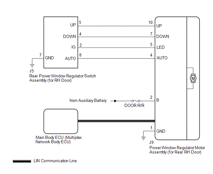
CAUTION / NOTICE / HINT
NOTICE:
Click here 
Click here
Click here
PROCEDURE
|
1. | READ VALUE USING TECHSTREAM (MAIN BODY) |
(a) Connect the Techstream to the DLC3.
(b) Turn the power switch on (IG).
(c) Turn the Techstream on.
(d) Enter the following menus: Body Electrical / Main Body / Data List.
(e) Read the Data List according to the display on the Techstream.
Body Electrical > Main Body > Data List|
Tester Display | Measurement Item |
Range | Normal Condition |
Diagnostic Note |
|---|---|---|---|---|
|
Communication RR-Door Motor |
Connection status between power window regulator motor assembly (for rear RH door) and main body ECU (multiplex network body ECU) |
STOP or OK | STOP: Communication stopped OK: Normal communication |
- |
|
Tester Display |
|---|
| Communication RR-Door Motor |
OK:
OK is displayed for each Data List item above.
| NG |  | GO TO LIN COMMUNICATION SYSTEM (Proceed to How to Proceed with Troubleshooting) |
|
| 2. |
READ VALUE USING TECHSTREAM (RR-DOOR MOTOR) |
(a) Enter the following menus: Body Electrical / RR-Door Motor / Data List.
(b) Read the Data List according to the display on the Techstream.
Body Electrical > RR-Door Motor > Data List|
Tester Display | Measurement Item |
Range | Normal Condition |
Diagnostic Note |
|---|---|---|---|---|
|
RR Door P/W Up SW | Rear RH door power window manual up switch signal |
OFF or ON | OFF: Rear RH door power window manual up switch not being operated ON: Rear RH door power window manual up switch being operated |
- |
| RR Door P/W Down SW |
Rear RH door power window manual down switch signal |
OFF or ON | OFF: Rear RH door power window manual down switch not being operated ON: Rear RH door power window manual down switch being operated |
- |
|
Tester Display |
|---|
| RR Door P/W Up SW |
|
RR Door P/W Down SW |
OK:
On the Techstream screen, ON or OFF is displayed accordingly.
| NG | | GO TO STEP 4 |
|
| 3. |
PERFORM ACTIVE TEST USING TECHSTREAM (RR-DOOR MOTOR) |
(a) Enter the following menus: Body Electrical / RR-Door Motor / Active Test.
(b) Perform the Active Test according to the display on the Techstream.
CAUTION:
Be careful to avoid injuries as this test causes vehicle parts to move. During the Active Test, the jam protection function will not operate.
Body Electrical > RR-Door Motor > Active Test|
Tester Display | Measurement Item |
Control Range | Diagnostic Note |
|---|---|---|---|
|
Power Window | Power window |
OFF / DOWN / UP | - |
|
Tester Display |
|---|
| Power Window |
OK:
Rear RH door power window operates normally.
| OK | | REPLACE MAIN BODY ECU (MULTIPLEX NETWORK BODY ECU) |
| NG | | REPLACE POWER WINDOW REGULATOR MOTOR ASSEMBLY (for Rear RH Door) |
| 4. |
INSPECT REAR POWER WINDOW REGULATOR SWITCH ASSEMBLY (for RH Door) |
(a) Remove the rear power window regulator switch assembly (for RH door).
Click here
(b) Inspect the rear power window regulator switch assembly (for RH door).
Click here
| NG | | REPLACE REAR POWER WINDOW REGULATOR SWITCH ASSEMBLY (for RH Door) |
|
| 5. |
CHECK HARNESS AND CONNECTOR (REAR POWER WINDOW REGULATOR SWITCH (for RH Door) - POWER WINDOW REGULATOR MOTOR (for Rear RH Door) AND BODY GROUND) |
(a) Disconnect the J9 power window regulator motor assembly (for rear RH door) connector.
(b) Measure the resistance according to the value(s) in the table below.
Standard Resistance:
|
Tester Connection | Condition |
Specified Condition |
|---|---|---|
|
J5-5 (UP) - J9-10 (UP) |
Always | Below 1 Ω |
|
J5-5 (UP) or J9-10 (UP) - Body ground |
Always | 10 kΩ or higher |
|
J5-4 (DOWN) - J9-7 (DOWN) |
Always | Below 1 Ω |
|
J5-4 (DOWN) or J9-7 (DOWN) - Body ground |
Always | 10 kΩ or higher |
|
J5-7 (GND) - Body ground |
Always | Below 1 Ω |
| OK | | REPLACE POWER WINDOW REGULATOR MOTOR ASSEMBLY (for Rear RH Door) |
| NG | | REPAIR OR REPLACE HARNESS OR CONNECTOR |
DESCRIPTION
When the power switch on (IG), the multiplex network master switch assembly sends remote up and down signals to each power window regulator motor assembly via LIN communication.
WIRING DIAGRAM
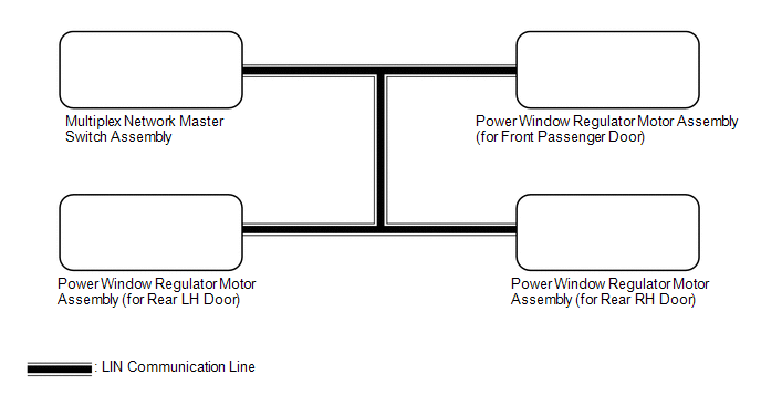
CAUTION / NOTICE / HINT
NOTICE:
Click here 
Click here
PROCEDURE
|
1. | READ VALUE USING TECHSTREAM (MAIN BODY) |
(a) Connect the Techstream to the DLC3.
(b) Turn the power switch on (IG).
(c) Turn the Techstream on.
(d) Enter the following menus: Body Electrical / Main Body / Data List.
(e) Read the Data List according to the display on the Techstream.
Body Electrical > Main Body > Data List|
Tester Display | Measurement Item |
Range | Normal Condition |
Diagnostic Note |
|---|---|---|---|---|
|
Communication P-Door Motor |
Connection status between power window regulator motor assembly (for front passenger door) and main body ECU (multiplex network body ECU) |
STOP or OK | STOP: Communication stopped OK: Normal communication |
- |
| Communication RR-Door Motor |
Connection status between power window regulator motor assembly (for rear RH door) and main body ECU (multiplex network body ECU) |
STOP or OK | STOP: Communication stopped OK: Normal communication |
- |
| Communication RL-Door Motor |
Connection status between power window regulator motor assembly (for rear LH door) and main body ECU (multiplex network body ECU) |
STOP or OK | STOP: Communication stopped OK: Normal communication |
- |
| Communication Master SW |
Connection status between multiplex network master switch assembly and main body ECU (multiplex network body ECU) |
STOP or OK | STOP: Communication stopped OK: Normal communication |
- |
|
Tester Display |
|---|
| Communication P-Door Motor |
|
Communication RR-Door Motor |
|
Communication RL-Door Motor |
|
Communication Master SW |
OK:
OK is displayed for each Data List item above.
| NG |  | GO TO LIN COMMUNICATION SYSTEM (Proceed to How to Proceed with Troubleshooting) |
|
| 2. |
READ VALUE USING TECHSTREAM (MASTER SWITCH) |
(a) Enter the following menus: Body Electrical / Master Switch / Data List.
(b) Read the Data List according to the display on the Techstream.
Body Electrical > Master Switch > Data List|
Tester Display | Measurement Item |
Range | Normal Condition |
Diagnostic Note |
|---|---|---|---|---|
|
P Door P/W Auto SW | Front passenger door power window auto switch signal |
OFF or ON | OFF: Front passenger door power window auto up or auto down switch not being operated ON: Front passenger door power window auto up or auto down switch being operated |
- |
| RR Door P/W Auto SW |
Rear RH door power window auto switch signal |
OFF or ON | OFF: Rear RH door power window auto up or auto down switch not being operated ON: Rear RH door power window auto up or auto down switch being operated |
- |
| RL Door P/W Auto SW |
Rear LH door power window auto switch signal |
OFF or ON | OFF: Rear LH door power window auto up or auto down switch not being operated ON: Rear LH door power window auto up or auto down switch being operated |
- |
| P Door P/W Up SW |
Front passenger door power window manual up switch signal |
OFF or ON | OFF: Front passenger door power window manual up switch not being operated ON: Front passenger door power window manual up switch being operated |
- |
| RR Door P/W up switch |
Rear RH door power window manual up switch signal |
OFF or ON | OFF: Rear RH door power window manual up switch not being operated ON: Rear RH door power window manual up switch being operated |
- |
| RL Door P/W up switch |
Rear LH door power window manual up switch signal |
OFF or ON | OFF: Rear LH door power window manual up switch not being operated ON: Rear LH door power window manual up switch being operated |
- |
| P Door P/W Down SW |
Front passenger door power window manual down switch signal |
OFF or ON | OFF: Front passenger door power window manual down switch not being operated ON: Front passenger door power window manual down switch being operated |
- |
| RR Door P/W Down SW |
Rear RH door power window manual down switch signal |
OFF or ON | OFF: Rear RH door power window manual down switch not being operated ON: Rear RH door power window manual down switch being operated |
- |
| RL Door P/W Down SW |
Rear LH door power window manual down switch signal |
OFF or ON | OFF: Rear LH door power window manual down switch not being operated ON: Rear LH door power window manual down switch being operated |
- |
| Window Lock Switch Status |
Window lock switch signal |
OFF or ON | OFF: Window lock switch off (not pushed in) ON: Window lock switch on (pushed in) |
- |
|
Tester Display |
|---|
| P Door P/W Auto SW |
|
RR Door P/W Auto SW |
|
RL Door P/W Auto SW |
|
P Door P/W Up SW |
|
RR Door P/W up switch |
|
RL Door P/W up switch |
|
P Door P/W Down SW |
|
RR Door P/W Down SW |
|
RL Door P/W Down SW |
|
Window Lock Switch Status |
OK:
On the Techstream screen, ON or OFF is displayed accordingly.
|
Result | Proceed to |
|---|---|
|
NG | A |
|
OK (Front passenger door power window remote up and down functions do not operate) |
B |
| OK (Rear LH door power window remote up and down functions do not operate) |
C |
| OK (Rear RH door power window remote up and down functions do not operate) |
| A |
| REPLACE MULTIPLEX NETWORK MASTER SWITCH ASSEMBLY |
| B |
| REPLACE POWER WINDOW REGULATOR MOTOR ASSEMBLY (for Front Passenger Door) |
| C |
| REPLACE POWER WINDOW REGULATOR MOTOR ASSEMBLY (for Rear LH Door or Rear RH Door) |
SYSTEM DESCRIPTION
POWER WINDOW CONTROL SYSTEM DESCRIPTION
(a) The power window control system controls the power window operation using the power window regulator motor assemblies. The main controls of this system are the multiplex network master switch assembly (mounted on the driver door), power window regulator switch assembly (mounted on the front passenger door) and rear power window regulator switch assemblies (mounted on the rear doors). Operating a window switch results in electrical power being transmitted to the corresponding power window regulator motor.
FUNCTION OF MAIN COMPONENTS
The power window control system consists of the following components:
|
Component | Outline |
|---|---|
|
Multiplex Network Master Switch Assembly |
|
| Power Window Regulator Switch Assembly |
|
| Rear Power Window Regulator Switch Assembly
|
|
| Power Window Regulator Motor Assembly |
|
SYSTEM FUNCTION
The power window control system has the following functions:
|
Function | Outline |
|---|---|
|
Manual up and down function | Function that causes the power window to go up while the power window switch is being pulled halfway up and to go down while it is being pushed halfway down. The power window stops as soon as the switch is released. |
|
Auto up and down function | Function that enables the power window of each door to be fully opened or closed by one full pull or push of the multiplex network master switch assembly, power window regulator switch assembly or rear power window regulator switch assembly. |
|
Window lock function |
|
| Jam protection function |
Function that automatically stops the power window and moves it downward if a foreign object gets jammed between the door and door glass during auto up or manual up operation. |
| Catch protection function |
Function that automatically stops the power window if something gets caught between the door and door glass during auto down or manual down operation. |
| Remote control function |
Function that allows the multiplex network master switch assembly to control manual and auto up and down operations of the front passenger door power window and rear door power windows. |
|
Key-off operation function |
HINT: If a power window is being operated by auto operation while the key-off operation function is on, and the driver door or passenger door is opened, the power window will stop operating. |
|
Key-linked function* |
|
| Wireless transmitter-linked function* |
When the main body ECU (multiplex network body ECU) receives an UNLOCK signal from the key for 3 seconds or more, the main body ECU (multiplex network body ECU) sends an operation request signal to the power window ECU in each power window regulator motor assembly. As a result, the power window regulator motor assembly open all of the power windows. |
|
Window open warning function (when approaching a tunnel) |
Displays a message on the multi-information display if any window is open when the vehicle is approaching a tunnel. |
|
Window open warning function | When the power switch is turned from on (IG) to off and the driver door is opened with the power window open, the buzzer in the combination meter assembly sounds once and a warning message is displayed on the multi-information display. |
|
Diagnosis | Function that allows diagnosis of the power window control system if any of the power window ECUs (built into each power window regulator motor assembly) detects a malfunction in the system. |
|
Fail-safe |
|
SYSTEM DIAGRAM
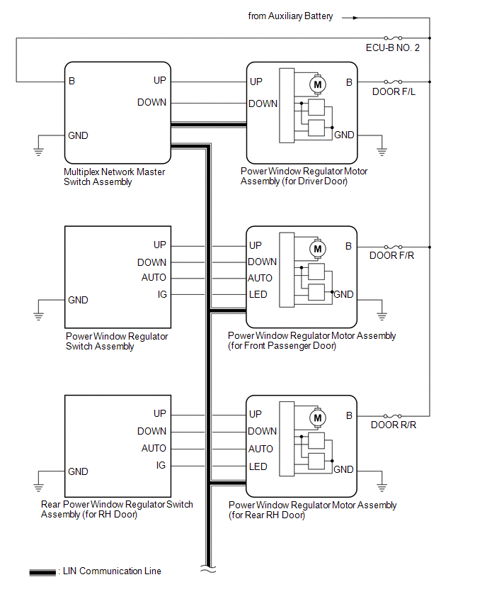
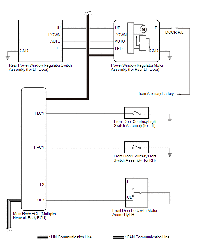
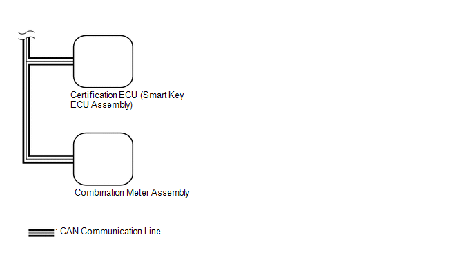 Communication Table
 |
Transmitting ECU | Receiving ECU |
Signal | Communication Method |
|---|---|---|---|
|
Multiplex Network Master Switch Assembly |
Power Window Regulator Motor Assembly (for Driver Door) |
Power window auto up and down signal |
LIN |
| Power window remote up and down signal |
LIN | |
| Main Body ECU (Multiplex Network Body ECU) |
| Power window operation permission signal |
LIN |
| Certification ECU (Smart Key ECU Assembly) |
Main Body ECU (Multiplex Network Body ECU) |
Wireless power window operation signal |
CAN |
| Main Body ECU (Multiplex Network Body ECU) |
Combination Meter Assembly | Window open warning request signal |
CAN |
TERMINALS OF ECU
CHECK MULTIPLEX NETWORK MASTER SWITCH ASSEMBLY

(a) Disconnect the I16 multiplex network master switch assembly connector.
(b) Measure the voltage and resistance according to the value(s) in the table below.
HINT:
Measure the values on the wire harness side with the connector disconnected.
|
Terminal No. (Symbol) | Wiring Color |
Terminal Description | Condition |
Specified Condition |
|---|---|---|---|---|
|
I16-11 (B) - I16-12 (GND) |
LA-R - W-B | Power supply |
Power switch off | 11 to 14 V |
|
I16-12 (GND) - Body ground |
W-B - Body ground | Ground |
Always | Below 1 Ω |
(c) Reconnect the I16 multiplex network master switch assembly connector.
(d) Measure the voltage according to the value(s) in the table below.
|
Terminal No. (Symbol) | Wiring Color |
Terminal Description | Condition |
Specified Condition |
|---|---|---|---|---|
|
I16-15 (DOWN) - I16-12 (GND) |
LA-V - W-B | Power window motor DOWN output |
Power switch on (IG), driver door power window regulator switch not pushed or not pulled |
11 to 14 V |
|
I16-15 (DOWN) - I16-12 (GND) |
LA-V - W-B | Power window motor DOWN output |
Power switch on (IG), driver door power window moving, driver door power window regulator switch pushed halfway down (Manual operation) |
Below 1 V |
|
I16-20 (UP) - I16-12 (GND) |
LA-L - W-B | Power window motor UP output |
Power switch on (IG), driver door power window regulator switch not pushed or not pulled |
11 to 14 V |
|
I16-20 (UP) - I16-12 (GND) |
LA-L - W-B | Power window motor UP output |
Power switch on (IG), driver door power window moving, driver door power window regulator switch pulled halfway up (Manual operation) |
Below 1 V |
CHECK POWER WINDOW REGULATOR SWITCH ASSEMBLY

(a) Disconnect the I2 power window regulator switch assembly connector.
(b) Measure the resistance according to the value(s) in the table below.
HINT:
Measure the values on the wire harness side with the connector disconnected.
|
Terminal No. (Symbol) | Wiring Color |
Terminal Description | Condition |
Specified Condition |
|---|---|---|---|---|
|
I2-7 (GND) - Body ground |
W-B - Body ground | Ground |
Always | Below 1 Ω |
(c) Reconnect the I2 power window regulator switch assembly connector.
(d) Measure the voltage according to the value(s) in the table below.
|
Terminal No. (Symbol) | Wiring Color |
Terminal Description | Condition |
Specified Condition |
|---|---|---|---|---|
|
I2-5 (UP) - I2-7 (GND) |
LA-W - W-B | Power window motor UP output |
Power switch on (IG), power window regulator switch assembly not pushed or not pulled |
11 to 14 V |
|
I2-5 (UP) - I2-7 (GND) |
LA-W - W-B | Power window motor UP output |
Power switch on (IG), front passenger door power window moving, power window regulator switch assembly pulled halfway up (Manual operation) |
Below 1 V |
|
I2-5 (UP) - I2-7 (GND) |
LA-W - W-B | Power window motor UP output |
Power switch on (IG), front passenger door power window fully open |
11 to 14 V |
|
I2-5 (UP) - I2-7 (GND) |
LA-W - W-B | Power window motor UP output |
Power switch on (IG), front passenger door power window moving, power window regulator switch assembly fully pulled up (Auto operation) |
Below 1 V |
|
I2-5 (UP) - I2-7 (GND) |
LA-W - W-B | Power window motor UP output |
Power switch on (IG), front passenger door power window fully closed |
11 to 14 V |
|
I2-4 (DOWN) - I2-7 (GND) |
LA-R - W-B | Power window motor DOWN output |
Power switch on (IG), power window regulator switch assembly not pushed or not pulled |
11 to 14 V |
|
I2-4 (DOWN) - I2-7 (GND) |
LA-R - W-B | Power window motor DOWN output |
Power switch on (IG), front passenger door power window moving, power window regulator switch assembly pushed halfway down (Manual operation) |
Below 1 V |
|
I2-4 (DOWN) - I2-7 (GND) |
LA-R - W-B | Power window motor DOWN output |
Power switch on (IG), front passenger door power window fully closed |
11 to 14 V |
|
I2-4 (DOWN) - I2-7 (GND) |
LA-R - W-B | Power window motor DOWN output |
Power switch on (IG), front passenger door power window moving, power window regulator switch assembly fully pushed down (Auto operation) |
Below 1 V |
|
I2-4 (DOWN) - I2-7 (GND) |
LA-R - W-B | Power window motor DOWN output |
Power switch on (IG), front passenger door power window fully open |
11 to 14 V |
|
I2-8 (AUTO) - I2-7 (GND) |
LA-G - W-B | Power window motor AUTO UP output |
Power switch on (IG), front passenger door power window fully open |
11 to 14 V |
|
I2-8 (AUTO) - I2-7 (GND) |
LA-G - W-B | Power window motor AUTO UP output |
Power switch on (IG), front passenger door power window moving, power window regulator switch assembly fully pulled up (Auto operation) |
Below 1 V |
|
I2-8 (AUTO) - I2-7 (GND) |
LA-G - W-B | Power window motor AUTO UP output |
Power switch on (IG), front passenger door power window fully closed |
11 to 14 V |
|
I2-8 (AUTO) - I2-7 (GND) |
LA-G - W-B | Power window motor AUTO DOWN output |
Power switch on (IG), front passenger door power window fully closed |
11 to 14 V |
|
I2-8 (AUTO) - I2-7 (GND) |
LA-G - W-B | Power window motor AUTO DOWN output |
Power switch on (IG), front passenger door power window moving, power window regulator switch assembly fully pushed down (Auto operation) |
Below 1 V |
|
I2-8 (AUTO) - I2-7 (GND) |
LA-G - W-B | Power window motor AUTO DOWN output |
Power switch on (IG), front passenger door power window fully open |
11 to 14 V |
CHECK REAR POWER WINDOW REGULATOR SWITCH ASSEMBLY (FOR LH DOOR)

(a) Disconnect the J6 rear power window regulator switch assembly (for LH door) connector.
(b) Measure the resistance according to the value(s) in the table below.
HINT:
Measure the values on the wire harness side with the connector disconnected.
|
Terminal No. (Symbol) | Wiring Color |
Terminal Description | Condition |
Specified Condition |
|---|---|---|---|---|
|
J6-7 (GND) - Body ground |
W-B - Body ground | Ground |
Always | Below 1 Ω |
(c) Reconnect the J6 rear power window regulator switch assembly (for LH door) connector.
(d) Measure the voltage according to the value(s) in the table below.
|
Terminal No. (Symbol) | Wiring Color |
Terminal Description | Condition |
Specified Condition |
|---|---|---|---|---|
|
J6-5 (UP) - J6-7 (GND) |
LA-B - W-B | Power window motor UP output |
Power switch on (IG), rear power window regulator switch assembly (for LH door) not pushed or not pulled |
11 to 14 V |
|
J6-5 (UP) - J6-7 (GND) |
LA-B - W-B | Power window motor UP output |
Power switch on (IG), rear LH door power window moving, rear power window regulator switch assembly (for LH door) pulled halfway up (Manual operation) | Below 1 V |
|
J6-5 (UP) - J6-7 (GND) |
LA-B - W-B | Power window motor UP output |
Power switch on (IG), rear LH door power window fully open |
11 to 14 V |
|
J6-5 (UP) - J6-7 (GND) |
LA-B - W-B | Power window motor UP output |
Power switch on (IG), rear LH door power window moving, rear power window regulator switch assembly (for LH door) fully pulled up (Auto operation) |
Below 1 V |
|
J6-5 (UP) - J6-7 (GND) |
LA-B - W-B | Power window motor UP output |
Power switch on (IG), rear LH door power window fully closed |
11 to 14 V |
|
J6-4 (DOWN) - J6-7 (GND) |
LA-R - W-B | Power window motor DOWN output |
Power switch on (IG), rear power window regulator switch assembly (for LH door) not pushed or not pulled |
11 to 14 V |
|
J6-4 (DOWN) - J6-7 (GND) |
LA-R - W-B | Power window motor DOWN output |
Power switch on (IG), rear LH door power window moving, rear power window regulator switch assembly (for LH door) pushed halfway down (Manual operation) | Below 1 V |
|
J6-4 (DOWN) - J6-7 (GND) |
LA-R - W-B | Power window motor DOWN output |
Power switch on (IG), rear LH door power window fully closed |
11 to 14 V |
|
J6-4 (DOWN) - J6-7 (GND) |
LA-R - W-B | Power window motor DOWN output |
Power switch on (IG), rear LH door power window moving, rear power window regulator switch assembly (for LH door) fully pushed down (Auto operation) | Below 1 V |
|
J6-4 (DOWN) - J6-7 (GND) |
LA-R - W-B | Power window motor DOWN output |
Power switch on (IG), rear LH door power window fully open |
11 to 14 V |
|
J6-8 (AUTO) - J6-7 (GND) |
LA-GR - W-B | Power window motor AUTO UP output |
Power switch on (IG), rear LH door power window fully open |
11 to 14 V |
|
J6-8 (AUTO) - J6-7 (GND) |
LA-GR - W-B | Power window motor AUTO UP output |
Power switch on (IG), rear LH door power window moving, rear power window regulator switch assembly (for LH door) fully pulled up (Auto operation) |
Below 1 V |
|
J6-8 (AUTO) - J6-7 (GND) |
LA-GR - W-B | Power window motor AUTO UP output |
Power switch on (IG), rear LH door power window fully closed |
11 to 14 V |
|
J6-8 (AUTO) - J6-7 (GND) |
LA-GR - W-B | Power window motor AUTO DOWN output |
Power switch on (IG), rear LH door power window fully closed |
11 to 14 V |
|
J6-8 (AUTO) - J6-7 (GND) |
LA-GR - W-B | Power window motor AUTO DOWN output |
Power switch on (IG), rear LH door power window moving, rear power window regulator switch assembly (for LH door) fully pushed down (Auto operation) | Below 1 V |
|
J6-8 (AUTO) - J6-7 (GND) |
LA-GR - W-B | Power window motor AUTO DOWN output |
Power switch on (IG), rear LH door power window fully open |
11 to 14 V |
CHECK REAR POWER WINDOW REGULATOR SWITCH ASSEMBLY (FOR RH DOOR)

(a) Disconnect the J5 rear power window regulator switch assembly (for RH door) connector.
(b) Measure the resistance according to the value(s) in the table below.
HINT:
Measure the values on the wire harness side with the connector disconnected.
|
Terminal No. (Symbol) | Wiring Color |
Terminal Description | Condition |
Specified Condition |
|---|---|---|---|---|
|
J5-7 (GND) - Body ground |
W-B - Body ground | Ground |
Always | Below 1 Ω |
(c) Reconnect the J5 rear power window regulator switch assembly (for RH door) connector.
(d) Measure the voltage according to the value(s) in the table below.
|
Terminal No. (Symbol) | Wiring Color |
Terminal Description | Condition |
Specified Condition |
|---|---|---|---|---|
|
J5-5 (UP) - J5-7 (GND) |
LA-B - W-B | Power window motor UP output |
Power switch on (IG), rear power window regulator switch assembly (for RH door) not pushed or not pulled |
11 to 14 V |
|
J5-5 (UP) - J5-7 (GND) |
LA-B - W-B | Power window motor UP output |
Power switch on (IG), rear RH door power window moving, rear power window regulator switch assembly (for RH door) pulled halfway up (Manual operation) | Below 1 V |
|
J5-5 (UP) - J5-7 (GND) |
LA-B - W-B | Power window motor UP output |
Power switch on (IG), rear RH door power window fully open |
11 to 14 V |
|
J5-5 (UP) - J5-7 (GND) |
LA-B - W-B | Power window motor UP output |
Power switch on (IG), rear RH door power window moving, rear power window regulator switch assembly (for RH door) fully pulled up (Auto operation) |
Below 1 V |
|
J5-5 (UP) - J5-7 (GND) |
LA-B - W-B | Power window motor UP output |
Power switch on (IG), rear RH door power window fully closed |
11 to 14 V |
|
J5-4 (DOWN) - J5-7 (GND) |
LA-R - W-B | Power window motor DOWN output |
Power switch on (IG), rear power window regulator switch assembly (for RH door) not pushed or not pulled |
11 to 14 V |
|
J5-4 (DOWN) - J5-7 (GND) |
LA-R - W-B | Power window motor DOWN output |
Power switch on (IG), rear RH door power window moving, rear power window regulator switch assembly (for RH door) pushed halfway down (Manual operation) | Below 1 V |
|
J5-4 (DOWN) - J5-7 (GND) |
LA-R - W-B | Power window motor DOWN output |
Power switch on (IG), rear RH door power window fully closed |
11 to 14 V |
|
J5-4 (DOWN) - J5-7 (GND) |
LA-R - W-B | Power window motor DOWN output |
Power switch on (IG), rear RH door power window moving, rear power window regulator switch assembly (for RH door) fully pushed down (Auto operation) | Below 1 V |
|
J5-4 (DOWN) - J5-7 (GND) |
LA-R - W-B | Power window motor DOWN output |
Power switch on (IG), rear RH door power window fully open |
11 to 14 V |
|
J5-8 (AUTO) - J5-7 (GND) |
LA-GR - W-B | Power window motor AUTO UP output |
Power switch on (IG), rear RH door power window fully open |
11 to 14 V |
|
J5-8 (AUTO) - J5-7 (GND) |
LA-GR - W-B | Power window motor AUTO UP output |
Power switch on (IG), rear RH door power window moving, rear power window regulator switch assembly (for RH door) fully pulled up (Auto operation) |
Below 1 V |
|
J5-8 (AUTO) - J5-7 (GND) |
LA-GR - W-B | Power window motor AUTO UP output |
Power switch on (IG), rear RH door power window fully closed |
11 to 14 V |
|
J5-8 (AUTO) - J5-7 (GND) |
LA-GR - W-B | Power window motor AUTO DOWN output |
Power switch on (IG), rear RH door power window fully closed |
11 to 14 V |
|
J5-8 (AUTO) - J5-7 (GND) |
LA-GR - W-B | Power window motor AUTO DOWN output |
Power switch on (IG), rear RH door power window moving, rear power window regulator switch assembly (for RH door) fully pushed down (Auto operation) | Below 1 V |
|
J5-8 (AUTO) - J5-7 (GND) |
LA-GR - W-B | Power window motor AUTO DOWN output |
Power switch on (IG), rear RH door power window fully open |
11 to 14 V |
CHECK POWER WINDOW REGULATOR MOTOR ASSEMBLY (FOR DRIVER DOOR)

(a) Disconnect the I20 power window regulator motor assembly (for driver door) connector.
(b) Measure the voltage and resistance according to the value(s) in the table below.
HINT:
Measure the values on the wire harness side with the connector disconnected.
|
Terminal No. (Symbol) | Wiring Color |
Terminal Description | Condition |
Specified Condition |
|---|---|---|---|---|
|
I20-1 (GND) - Body ground |
W-B - Body ground | Ground |
Always | Below 1 Ω |
|
I20-2 (B) - Body ground |
GR - Body ground | Power supply |
Power switch off | 11 to 14 V |
(c) Reconnect the I20 power window regulator motor assembly (for driver door) connector.
(d) Measure the voltage according to the value(s) in the table below.
|
Terminal No. (Symbol) | Wiring Color |
Terminal Description | Condition |
Specified Condition |
|---|---|---|---|---|
|
I20-7 (DOWN) - I20-1 (GND) |
LA-V - W-B | Power window motor DOWN input |
Power switch on (IG), multiplex network master switch assembly (driver door power window regulator switch) not pushed or not pulled |
11 to 14 V |
|
I20-7 (DOWN) - I20-1 (GND) |
LA-V - W-B | Power window motor DOWN input |
Power switch on (IG), driver door power window moving, multiplex network master switch assembly (driver door power window regulator switch) pushed halfway down (Manual operation) |
Below 1 V |
|
I20-7 (DOWN) - I20-1 (GND) |
LA-V - W-B | Power window motor DOWN input |
Power switch on (IG), driver door power window fully closed |
11 to 14 V |
|
I20-7 (DOWN) - I20-1 (GND) |
LA-V - W-B | Power window motor DOWN input |
Power switch on (IG), driver door power window moving, multiplex network master switch assembly (driver door power window regulator switch) fully pushed down (Auto operation) | Below 1 V |
|
I20-7 (DOWN) - I20-1 (GND) |
LA-V - W-B | Power window motor DOWN input |
Power switch on (IG), driver door power window fully open |
11 to 14 V |
|
I20-10 (UP) - I20-1 (GND) |
LA-L - W-B | Power window motor UP input |
Power switch on (IG), multiplex network master switch assembly (driver door power window regulator switch) not pushed or not pulled |
11 to 14 V |
|
I20-10 (UP) - I20-1 (GND) |
LA-L - W-B | Power window motor UP input |
Power switch on (IG), driver door power window moving, multiplex network master switch assembly (driver door power window regulator switch) pulled halfway up (Manual operation) |
Below 1 V |
|
I20-10 (UP) - I20-1 (GND) |
LA-L - W-B | Power window motor UP input |
Power switch on (IG), multiplex network master switch assembly (driver door power window regulator switch) fully open |
11 to 14 V |
|
I20-10 (UP) - I20-1 (GND) |
LA-L - W-B | Power window motor UP input |
Power switch on (IG), driver door power window moving, multiplex network master switch assembly (driver door power window regulator switch) fully pulled up (Auto operation) | Below 1 V |
|
I20-10 (UP) - I20-1 (GND) |
LA-L - W-B | Power window motor UP input |
Power switch on (IG), driver door power window fully closed |
11 to 14 V |
CHECK POWER WINDOW REGULATOR MOTOR ASSEMBLY (FOR FRONT PASSENGER DOOR)

(a) Disconnect the I4 power window regulator motor assembly (for front passenger door) connector.
(b) Measure the voltage and resistance according to the value(s) in the table below.
HINT:
Measure the values on the wire harness side with the connector disconnected.
|
Terminal No. (Symbol) | Wiring Color |
Terminal Description | Condition |
Specified Condition |
|---|---|---|---|---|
|
I4-1 (GND) - Body ground |
W-B - Body ground | Ground |
Always | Below 1 Ω |
|
I4-2 (B) - Body ground |
GR - Body ground | Power supply |
Power switch off | 11 to 14 V |
(c) Reconnect the I4 power window regulator motor assembly (for front passenger door) connector.
(d) Measure the voltage according to the value(s) in the table below.
|
Terminal No. (Symbol) | Wiring Color |
Terminal Description | Condition |
Specified Condition |
|---|---|---|---|---|
|
I4-4 (AUTO) - I4-1 (GND) |
LA-G - W-B | Power window motor AUTO UP input |
Power switch on (IG), front passenger door power window fully open |
11 to 14 V |
|
I4-4 (AUTO) - I4-1 (GND) |
LA-G - W-B | Power window motor AUTO UP input |
Power switch on (IG), front passenger door power window moving, power window regulator switch assembly fully pulled up (Auto operation) |
Below 1 V |
|
I4-4 (AUTO) - I4-1 (GND) |
LA-G - W-B | Power window motor AUTO UP input |
Power switch on (IG), front passenger door power window fully closed |
11 to 14 V |
|
I4-4 (AUTO) - I4-1 (GND) |
LA-G - W-B | Power window motor AUTO DOWN input |
Power switch on (IG), front passenger door power window fully closed |
11 to 14 V |
|
I4-4 (AUTO) - I4-1 (GND) |
LA-G - W-B | Power window motor AUTO DOWN input |
Power switch on (IG), front passenger door power window moving, power window regulator switch assembly fully pushed down (Auto operation) |
Below 1 V |
|
I4-4 (AUTO) - I4-1 (GND) |
LA-G - W-B | Power window motor AUTO DOWN input |
Power switch on (IG), front passenger door power window fully open |
11 to 14 V |
|
I4-7 (DOWN) - I4-1 (GND) |
LA-R - W-B | Power window motor DOWN input |
Power switch on (IG), power window regulator switch assembly not pushed or not pulled |
11 to 14 V |
|
I4-7 (DOWN) - I4-1 (GND) |
LA-R - W-B | Power window motor DOWN input |
Power switch on (IG), front passenger door power window moving, power window regulator switch assembly pushed halfway down (Manual operation) |
Below 1 V |
|
I4-7 (DOWN) - I4-1 (GND) |
LA-R - W-B | Power window motor DOWN input |
Power switch on (IG), front passenger door power window fully closed |
11 to 14 V |
|
I4-7 (DOWN) - I4-1 (GND) |
LA-R - W-B | Power window motor DOWN input |
Power switch on (IG), front passenger door power window moving, power window regulator switch assembly fully pushed down (Auto operation) |
Below 1 V |
|
I4-7 (DOWN) - I4-1 (GND) |
LA-R - W-B | Power window motor DOWN input |
Power switch on (IG), front passenger door power window fully open |
11 to 14 V |
|
I4-10 (UP) - I4-1 (GND) |
LA-W - W-B | Power window motor UP input |
Power switch on (IG), power window regulator switch assembly not pushed or not pulled |
11 to 14 V |
|
I4-10 (UP) - I4-1 (GND) |
LA-W - W-B | Power window motor UP input |
Power switch on (IG), front passenger door power window moving, power window regulator switch assembly pulled halfway up (Manual operation) |
Below 1 V |
|
I4-10 (UP) - I4-1 (GND) |
LA-W - W-B | Power window motor UP input |
Power switch on (IG), front passenger door power window fully open |
11 to 14 V |
|
I4-10 (UP) - I4-1 (GND) |
LA-W - W-B | Power window motor UP input |
Power switch on (IG), front passenger door power window moving, power window regulator switch assembly fully pulled up (Auto operation) |
Below 1 V |
|
I4-10 (UP) - I4-1 (GND) |
LA-W - W-B | Power window motor UP input |
Power switch on (IG), front passenger door power window fully closed |
11 to 14 V |
CHECK POWER WINDOW REGULATOR MOTOR ASSEMBLY (FOR REAR LH DOOR)

(a) Disconnect the J10 power window regulator motor assembly (for rear LH door) connector.
(b) Measure the voltage and resistance according to the value(s) in the table below.
HINT:
Measure the values on the wire harness side with the connector disconnected.
|
Terminal No. (Symbol) | Wiring Color |
Terminal Description | Condition |
Specified Condition |
|---|---|---|---|---|
|
J10-1 (GND) - Body ground |
W-B - Body ground | Ground |
Always | Below 1 Ω |
|
J10-2 (B) - Body ground |
B - Body ground | Power supply |
Power switch off | 11 to 14 V |
(c) Reconnect the J10 power window regulator motor assembly (for rear LH door) connector.
(d) Measure the voltage according to the value(s) in the table below.
|
Terminal No. (Symbol) | Wiring Color |
Terminal Description | Condition |
Specified Condition |
|---|---|---|---|---|
|
J10-4 (AUTO) - J10-1 (GND) |
LA-GR - W-B | Power window motor AUTO UP input |
Power switch on (IG), rear LH door power window fully open |
11 to 14 V |
|
J10-4 (AUTO) - J10-1 (GND) |
LA-GR - W-B | Power window motor AUTO UP input |
Power switch on (IG), rear LH door power window moving, rear power window regulator switch assembly (for LH door) fully pulled up (Auto operation) |
Below 1 V |
|
J10-4 (AUTO) - J10-1 (GND) |
LA-GR - W-B | Power window motor AUTO UP input |
Power switch on (IG), rear LH door power window fully closed |
11 to 14 V |
|
J10-4 (AUTO) - J10-1 (GND) |
LA-GR - W-B | Power window motor AUTO DOWN input |
Power switch on (IG), rear LH door power window fully closed |
11 to 14 V |
|
J10-4 (AUTO) - J10-1 (GND) |
LA-GR - W-B | Power window motor AUTO DOWN input |
Power switch on (IG), rear LH door power window moving, rear power window regulator switch assembly (for LH door) fully pushed down (Auto operation) | Below 1 V |
|
J10-4 (AUTO) - J10-1 (GND) |
LA-GR - W-B | Power window motor AUTO DOWN input |
Power switch on (IG), rear LH door power window fully open |
11 to 14 V |
|
J10-7 (DOWN) - J10-1 (GND) |
LA-R - W-B | Power window motor DOWN input |
Power switch on (IG), rear power window regulator switch assembly (for LH door) not pushed or not pulled |
11 to 14 V |
|
J10-7 (DOWN) - J10-1 (GND) |
LA-R - W-B | Power window motor DOWN input |
Power switch on (IG), rear LH door power window moving, rear power window regulator switch assembly (for LH door) pushed halfway down (Manual operation) | Below 1 V |
|
J10-7 (DOWN) - J10-1 (GND) |
LA-R - W-B | Power window motor DOWN input |
Power switch on (IG), rear LH door power window fully closed |
11 to 14 V |
|
J10-7 (DOWN) - J10-1 (GND) |
LA-R - W-B | Power window motor DOWN input |
Power switch on (IG), rear LH door power window moving, rear power window regulator switch assembly (for LH door) fully pushed down (Auto operation) | Below 1 V |
|
J10-7 (DOWN) - J10-1 (GND) |
LA-R - W-B | Power window motor DOWN input |
Power switch on (IG), rear LH door power window fully open |
11 to 14 V |
|
J10-10 (UP) - J10-1 (GND) |
LA-B - W-B | Power window motor UP input |
Power switch on (IG), rear power window regulator switch assembly (for LH door) not pushed or not pulled |
11 to 14 V |
|
J10-10 (UP) - J10-1 (GND) |
LA-B - W-B | Power window motor UP input |
Power switch on (IG), rear LH door power window moving, rear power window regulator switch assembly (for LH door) pulled halfway up (Manual operation) | Below 1 V |
|
J10-10 (UP) - J10-1 (GND) |
LA-B - W-B | Power window motor UP input |
Power switch on (IG), rear LH door power window fully open |
11 to 14 V |
|
J10-10 (UP) - J10-1 (GND) |
LA-B - W-B | Power window motor UP input |
Power switch on (IG), rear LH door power window moving, rear power window regulator switch assembly (for LH door) fully pulled up (Auto operation) |
Below 1 V |
|
J10-10 (UP) - J10-1 (GND) |
LA-B - W-B | Power window motor UP input |
Power switch on (IG), rear LH door power window fully closed |
11 to 14 V |
CHECK POWER WINDOW REGULATOR MOTOR ASSEMBLY (FOR REAR RH DOOR)

(a) Disconnect the J9 power window regulator motor assembly (for rear RH door) connector.
(b) Measure the voltage and resistance according to the value(s) in the table below.
HINT:
Measure the values on the wire harness side with the connector disconnected.
|
Terminal No. (Symbol) | Wiring Color |
Terminal Description | Condition |
Specified Condition |
|---|---|---|---|---|
|
J9-1 (GND) - Body ground |
W-B - Body ground | Ground |
Always | Below 1 Ω |
|
J9-2 (B) - Body ground |
B - Body ground | Power supply |
Power switch off | 11 to 14 V |
(c) Reconnect the J9 power window regulator motor assembly (for rear RH door) connector.
(d) Measure the voltage according to the value(s) in the table below.
|
Terminal No. (Symbol) | Wiring Color |
Terminal Description | Condition |
Specified Condition |
|---|---|---|---|---|
|
J9-4 (AUTO) - J9-1 (GND) |
LA-GR - W-B | Power window motor AUTO UP input |
Power switch on (IG), rear RH door power window fully open |
11 to 14 V |
|
J9-4 (AUTO) - J9-1 (GND) |
LA-GR - W-B | Power window motor AUTO UP input |
Power switch on (IG), rear RH door power window moving, rear power window regulator switch assembly (for RH door) fully pulled up (Auto operation) |
Below 1 V |
|
J9-4 (AUTO) - J9-1 (GND) |
LA-GR - W-B | Power window motor AUTO UP input |
Power switch on (IG), rear RH door power window fully closed |
11 to 14 V |
|
J9-4 (AUTO) - J9-1 (GND) |
LA-GR - W-B | Power window motor AUTO DOWN input |
Power switch on (IG), rear RH door power window fully closed |
11 to 14 V |
|
J9-4 (AUTO) - J9-1 (GND) |
LA-GR - W-B | Power window motor AUTO DOWN input |
Power switch on (IG), rear RH door power window moving, rear power window regulator switch assembly (for RH door) fully pushed down (Auto operation) | Below 1 V |
|
J9-4 (AUTO) - J9-1 (GND) |
LA-GR - W-B | Power window motor AUTO DOWN input |
Power switch on (IG), rear RH door power window fully open |
11 to 14 V |
|
J9-7 (DOWN) - J9-1 (GND) |
LA-R - W-B | Power window motor DOWN input |
Power switch on (IG), rear power window regulator switch assembly (for RH door) not pushed or not pulled |
11 to 14 V |
|
J9-7 (DOWN) - J9-1 (GND) |
LA-R - W-B | Power window motor DOWN input |
Power switch on (IG), rear RH door power window moving, rear power window regulator switch assembly (for RH door) pushed halfway down (Manual operation) | Below 1 V |
|
J9-7 (DOWN) - J9-1 (GND) |
LA-R - W-B | Power window motor DOWN input |
Power switch on (IG), rear RH door power window fully closed |
11 to 14 V |
|
J9-7 (DOWN) - J9-1 (GND) |
LA-R - W-B | Power window motor DOWN input |
Power switch on (IG), rear RH door power window moving, rear power window regulator switch assembly (for RH door) fully pushed down (Auto operation) | Below 1 V |
|
J9-7 (DOWN) - J9-1 (GND) |
LA-R - W-B | Power window motor DOWN input |
Power switch on (IG), rear RH door power window fully open |
11 to 14 V |
|
J9-10 (UP) - J9-1 (GND) |
LA-B - W-B | Power window motor UP input |
Power switch on (IG), rear power window regulator switch assembly (for RH door) not pushed or not pulled |
11 to 14 V |
|
J9-10 (UP) - J9-1 (GND) |
LA-B - W-B | Power window motor UP input |
Power switch on (IG), rear RH door power window moving, rear power window regulator switch assembly (for RH door) pulled halfway up (Manual operation) | Below 1 V |
|
J9-10 (UP) - J9-1 (GND) |
LA-B - W-B | Power window motor UP input |
Power switch on (IG), rear RH door power window fully open |
11 to 14 V |
|
J9-10 (UP) - J9-1 (GND) |
LA-B - W-B | Power window motor UP input |
Power switch on (IG), rear RH door power window moving, rear power window regulator switch assembly (for RH door) fully pulled up (Auto operation) |
Below 1 V |
|
J9-10 (UP) - J9-1 (GND) |
LA-B - W-B | Power window motor UP input |
Power switch on (IG), rear RH door power window fully closed |
11 to 14 V |
CHECK INSTRUMENT PANEL JUNCTION BLOCK ASSEMBLY AND MAIN BODY ECU (MULTIPLEX NETWORK BODY ECU)
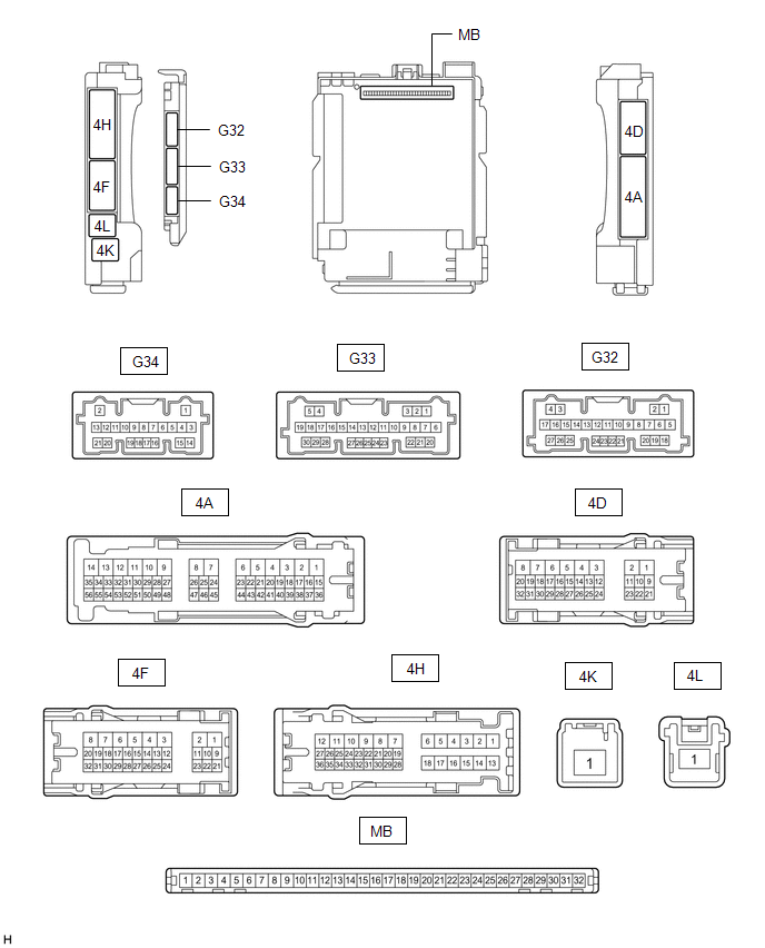
(a) Remove the main body ECU (multiplex network body ECU) from the instrument panel junction block assembly.
Click here 
(b) Measure the resistance according to the value(s) in the table below.
HINT:
Measure the values on the wire harness side with the connectors connected.
|
Terminal No. (Symbol) | Wiring Color |
Terminal Description | Condition |
Specified Condition |
|---|---|---|---|---|
|
G32-19 (GND2) - Body ground |
W-B - Body ground | Ground |
Always | Below 1 Ω |
(c) Reconnect the instrument panel junction block assembly connectors.
(d) Measure the voltage and resistance according to the value(s) in the table below.
|
Terminal No. (Symbol) | Wiring Color |
Terminal Description | Condition |
Specified Condition |
|---|---|---|---|---|
|
MB-11 (GND1) - Body ground |
- | Ground |
Always | Below 1 Ω |
|
MB-31 (BECU) - Body ground |
- | Auxiliary battery power supply |
Power switch off | 11 to 14 V |
|
MB-30 (ACC) - Body ground |
- | ACC power supply |
Power switch on (ACC) |
11 to 14 V |
|
MB-30 (ACC) - Body ground |
- | ACC power supply |
Power switch off | Below 1 V |
|
MB-32 (IG) - Body ground |
- | IG power supply |
Power switch on (IG) |
11 to 14 V |
|
MB-32 (IG) - Body ground |
- | IG power supply |
Power switch off or on (ACC) |
Below 1 V |
(e) Install the main body ECU (multiplex network body ECU) to the instrument panel junction block assembly.
Click here
(f) Measure the voltage and check for pulses according to the value(s) in the table below.
|
Terminal No. (Symbol) | Wiring Color |
Terminal Description | Condition |
Specified Condition |
|---|---|---|---|---|
|
G33-1 (FLCY) - Body ground |
W - Body ground | Front door courtesy light switch (for LH) input |
Front door LH open | Below 1 V |
|
G33-1 (FLCY) - Body ground |
W - Body ground | Front door courtesy light switch (for LH) input |
Front door LH closed |
11 to 14 V |
|
G33-6 (FRCY) - Body ground |
BE - Body ground | Front door courtesy light switch (for RH) input |
Front door RH open | Below 1 V |
|
G33-6 (FRCY) - Body ground |
BE - Body ground | Front door courtesy light switch (for RH) input |
Front door RH closed |
11 to 14 V |
|
G34-18 (L2) - Body ground |
LG - Body ground | Driver door key-linked lock input |
Driver door key cylinder turned to lock |
Below 1 V |
|
G34-18 (L2) - Body ground |
LG - Body ground | Driver door key-linked lock input |
Driver door key cylinder not turned |
11 to 14 V |
|
G34-17 (UL3) - Body ground |
BE - Body ground | Driver door key-linked unlock input |
Driver door key cylinder turned to unlock |
Below 1 V |
|
G34-17 (UL3) - Body ground |
BE - Body ground | Driver door key-linked unlock input |
Driver door key cylinder not turned |
11 to 14 V |
Toyota Avalon (XX50) 2019-2022 Service & Repair Manual > Hybrid Control System: Indicator Circuit. Inverter Low-voltage Circuit. Motor High-voltage Circuit
Indicator Circuit DESCRIPTION In accordance with the shift lever position, each shift position indicator light will turn on. WIRING DIAGRAM PROCEDURE 1. CHECK SHIFT POSITION INDICATOR (a) Turn the power switch on (ACC). (b) Check that each shift position indicator light turns on correctly. Result Pr ...