DATA LIST / ACTIVE TEST
ACTIVE TEST
HINT:
Using the Techstream to perform Active Tests allows relays, VSVs, actuators and other items to be operated without removing any parts. This non-intrusive functional inspection can be very useful because intermittent operation may be discovered before parts or wiring is disturbed. Performing Active Tests early in troubleshooting is one way to save diagnostic time. Data List information can be displayed while performing Active Tests.
(a) Connect the Techstream to the DLC3.
(b) Turn the power switch on (IG).
(c) Turn the Techstream on.
(d) Enter the following menus: Body Electrical / Air Conditioner / Active Test.
(e) Perform the Active Test according to the display on the Techstream.
Body Electrical > Air Conditioner > Active Test|
Tester Display | Measurement Item |
Control Range | Diagnostic Note |
|---|---|---|---|
|
Defogger Relay (Rear) | Rear window defogger wire (Back Window glass) |
OFF or ON | - |
DIAGNOSIS SYSTEM
CHECK DLC3
(a) Check the DLC3.
Click here 
INSPECT AUXILIARY BATTERY VOLTAGE
(a) Measure the auxiliary battery voltage with the power switch off.
Standard Voltage:
11 to 14 V
If the voltage is below 11 V, recharge or replace the auxiliary battery.
CAUTION / NOTICE / HINT
HINT:
PROCEDURE
|
1. | VEHICLE BROUGHT TO WORKSHOP |
|
| 2. |
CUSTOMER PROBLEM ANALYSIS |
HINT:
|
What |
Vehicle model, system name |
|
When |
Date, time, occurrence frequency |
|
Where |
Road conditions |
|
Under what conditions? |
Driving conditions, weather conditions |
|
How did it happen? |
Problem symptoms |
|
| 3. |
PRE-CHECK |
(a) Measure the auxiliary battery voltage with the power switch off.
Standard Voltage:
11 to 14 V
If the voltage is below 11 V, recharge or replace the auxiliary battery before proceeding to the next step.
(b) Check the fuses and relays.
(c) Check the connector connections and terminals to make sure that there are no abnormalities such as loose connections, deformation, etc.
(d) Check the vehicle specifications.
|
| 4. |
CHECK COMMUNICATION FUNCTION OF CAN COMMUNICATION SYSTEM* |
(a) Using the Techstream, check for CAN communication system DTCs.
Click here

|
Result | Proceed to |
|---|---|
|
CAN DTCs are not output |
A |
| CAN DTCs are output |
B |
| B |
 | GO TO CAN COMMUNICATION SYSTEM |
|
| 5. |
PROBLEM SYMPTOMS TABLE |
(a) Refer to Problem Symptoms Table.
Click here
|
Result | Proceed to |
|---|---|
|
Fault is not listed in Problem Symptoms Table |
A |
| Fault is listed in Problem Symptoms Table |
B |
| B |
| GO TO STEP 7 |
|
| 6. |
OVERALL ANALYSIS AND TROUBLESHOOTING* |
(a) Operation Check
Click here
(b) Terminals of ECU
Click here
(c) Data List / Active Test
Click here
(d) On-vehicle Inspection
|
| 7. |
REPAIR OR REPLACE |
|
| 8. |
CONFIRMATION TEST |
| NEXT | | END |
OPERATION CHECK
CHECK WINDOW DEFOGGER SYSTEM
(a) Turn the power switch on (IG).
(b) Check that the rear window defogger wire becomes warm by operating the rear window defogger switch of the radio and display receiver assembly.
(c) When the vehicle is stopped, confirm that the window defogger system operation stops after approximately 15 minutes.
NOTICE:
If the auxiliary battery voltage becomes low, auxiliary battery load control will operate in order to ensure sufficient power is supplied to the power steering system. In this case, the window defogger system may not operate.
HINT:
The window defogger system is linked with the mirror heater function.
PARTS LOCATION
ILLUSTRATION

|
*1 | DEF RELAY |
*2 | REAR WINDOW DEFOGGER WIRE |
|
*3 | NO. 1 ENGINE ROOM RELAY BLOCK AND NO. 1 JUNCTION BLOCK ASSEMBLY - DEF FUSE | *4 |
BACK WINDOW GLASS |
ILLUSTRATION
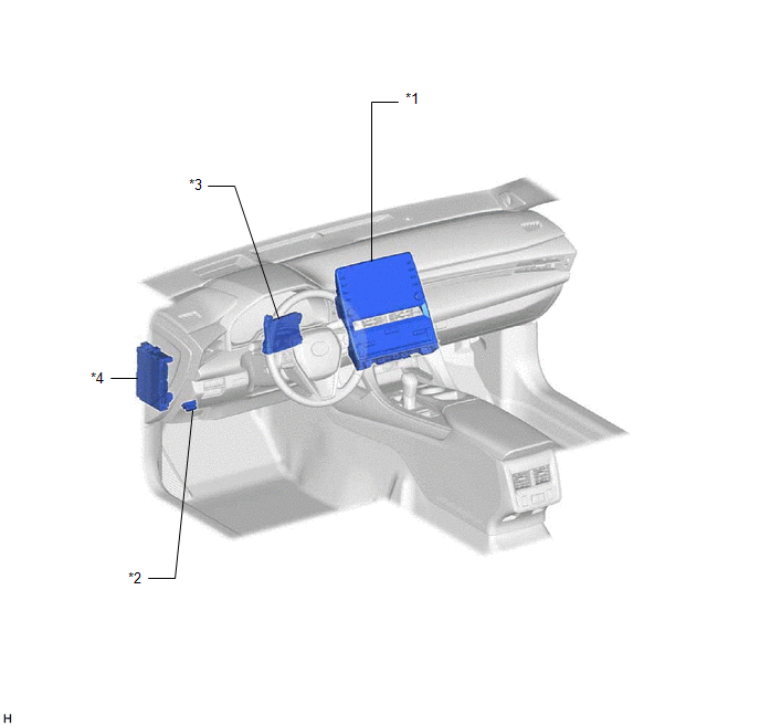
|
*1 | REAR WINDOW DEFOGGER SWITCH (RADIO AND DISPLAY RECEIVER ASSEMBLY) |
*2 | DLC3 |
|
*3 | AIR CONDITIONING AMPLIFIER ASSEMBLY |
*4 | INSTRUMENT PANEL JUNCTION BLOCK ASSEMBLY - ECU-IG1 NO. 3 FUSE |
PRECAUTION
PRECAUTION FOR DISCONNECTING CABLE FROM NEGATIVE AUXILIARY BATTERY TERMINAL
NOTICE:
When disconnecting the cable from the negative (-) auxiliary battery terminal, initialize the following systems after the cable is reconnected.
|
System Name | See Procedure |
|---|---|
|
Lane Departure Alert System (w/ Steering Control) |
|
|
Intelligent Clearance Sonar System | |
|
Parking Assist Monitor System | |
|
Panoramic View Monitor System | |
|
Pre-collision System | |
|
Lighting System (for HV Model with Cornering Light) |
PROBLEM SYMPTOMS TABLE
HINT:
|
Symptom | Suspected Area |
Link |
|---|---|---|
| Window defogger system does not operate |
Proceed to the "Rear Window Defogger System does not Operate" |
|
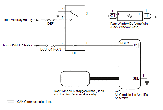
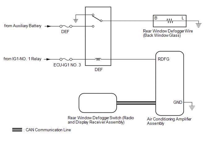
DESCRIPTION
When the rear window defogger switch on the radio and display receiver assembly is pressed, the operation signal is transmitted to the air conditioning amplifier assembly via CAN communication. When the air conditioning amplifier assembly receives the signal, it turns on the DEF relay to operate the window defogger system.
WIRING DIAGRAM
CAUTION / NOTICE / HINT
NOTICE:
PROCEDURE
|
1. | CHECK AIR CONDITIONING SYSTEM |
(a) Check the air conditioning system.
HINT:
Both the window defogger system operation signal and air conditioning system operation signal are transmitted to the air conditioning amplifier assembly via the same communication line.
OK:
The air conditioning system operates normally.
| NG |  | GO TO AIR CONDITIONING SYSTEM |
|
| 2. |
PERFORM ACTIVE TEST USING TECHSTREAM |
(a) Connect the Techstream to the DLC3.
(b) Turn the power switch on (IG).
(c) Turn the Techstream on.
(d) Enter the following menus: Body Electrical / Air Conditioner / Active Test.
(e) Perform the Active Test according to the display on the Techstream.
Body Electrical > Air Conditioner > Active Test|
Tester Display | Measurement Item |
Control Range | Diagnostic Note |
|---|---|---|---|
|
Defogger Relay (Rear) | Rear window defogger wire (Back window glass) |
OFF or ON | - |
|
Tester Display |
|---|
| Defogger Relay (Rear) |
OK:
The window defogger system operates normally.
| NG | | GO TO STEP 4 |
|
| 3. |
REPLACE REAR WINDOW DEFOGGER SWITCH (RADIO AND DISPLAY RECEIVER ASSEMBLY) |
(a) Replace the rear window defogger switch (radio and display receiver assembly) with a new or known good one.
Click here 
(b) Check that the window defogger system operates normally.
Click here
OK:
The window defogger system operates normally.
| OK | | END (REAR WINDOW DEFOGGER SWITCH (RADIO AND DISPLAY RECEIVER ASSEMBLY WAS DEFECTIVE)) |
| NG | | REPLACE AIR CONDITIONING AMPLIFIER ASSEMBLY |
| 4. |
INSPECT DEF RELAY |
(a) Inspect the DEF relay.
Click here
| NG | | REPLACE DEF RELAY |
|
| 5. |
CHECK HARNESS AND CONNECTOR (DEF RELAY - IG1-NO. 1 RELAY AND AUXILIARY BATTERY) |
| (a) Remove the DEF relay from the No. 1 engine room relay block and No. 1 junction block assembly. |
|
(b) Measure the voltage according to the value(s) in the table below.
Standard Voltage:
|
Tester Connection | Condition |
Specified Condition |
|---|---|---|
|
DEF relay holder terminal 2 - Body ground |
Power switch on (IG) |
11 to 14 V |
|
DEF relay holder terminal 5 - Body ground |
Power switch off | 11 to 14 V |
| NG | | REPAIR OR REPLACE HARNESS OR CONNECTOR |
|
| 6. |
CHECK HARNESS AND CONNECTOR (DEF RELAY - AIR CONDITIONING AMPLIFIER ASSEMBLY) |
| (a) Remove the DEF relay from the No. 1 engine room relay block and No. 1 junction block assembly. |
|
(b) Disconnect the G35 air conditioning amplifier assembly connector.
(c) Measure the resistance according to the value(s) in the table below.
Standard Resistance:
|
Tester Connection | Condition |
Specified Condition |
|---|---|---|
|
DEF relay holder terminal 1 - G35-5 (RDFG) |
Always | Below 1 Ω |
|
DEF relay holder terminal 1 or G35-5 (RDFG) - Body ground |
Always | 10 kΩ or higher |
| NG | | REPAIR OR REPLACE HARNESS OR CONNECTOR |
|
| 7. |
CHECK HARNESS AND CONNECTOR (DEF RELAY - REAR WINDOW DEFOGGER WIRE (BACK WINDOW GLASS)) |
| (a) Remove the DEF relay from the No. 1 engine room relay block and No. 1 junction block assembly. |
|
(b) Disconnect the K21 rear window defogger wire (back window glass) wire connector.
(c) Measure the resistance according to the value(s) in the table below.
Standard Resistance:
|
Tester Connection | Condition |
Specified Condition |
|---|---|---|
|
DEF relay holder terminal 3 - K21-1 (B) |
Always | Below 1 Ω |
|
DEF relay holder terminal 3 or K21-1 (B) - Body ground |
Always | 10 kΩ or higher |
| NG | | REPAIR OR REPLACE HARNESS OR CONNECTOR |
|
| 8. |
CHECK HARNESS AND CONNECTOR (REAR WINDOW DEFOGGER WIRE (BACK WINDOW GLASS) - BODY GROUND) |
(a) Disconnect the L1 rear window defogger wire (back window glass) connector.
(b) Measure the resistance according to the value(s) in the table below.
Standard Resistance:
|
Tester Connection | Condition |
Specified Condition |
|---|---|---|
|
L1-1 (L) - Body ground |
Always | Below 1 Ω |
| NG | | REPAIR OR REPLACE HARNESS OR CONNECTOR |
|
| 9. |
CHECK AIR CONDITIONING AMPLIFIER ASSEMBLY |
| (a) Reconnect the G35 air conditioning amplifier assembly connector. |
|
(b) Reinstall the DEF relay.
(c) Remove the air conditioning amplifier assembly with its connectors still connected.
Click here
(d) Measure the voltage according to the value(s) in the table below.
Standard Voltage:
|
Tester Connection | Condition |
Specified Condition |
|---|---|---|
|
G35-5 (RDFG) - G35-4 (GND) |
Power switch on (IG), rear window defogger switch on |
Below 1 V |
|
G35-5 (RDFG) - G35-4 (GND) |
Power switch on (IG), rear window defogger switch off |
11 to 14 V |
| OK | | REPAIR OR REPLACE BACK WINDOW GLASS |
| NG | | REPLACE AIR CONDITIONING AMPLIFIER ASSEMBLY |
SYSTEM DESCRIPTION
GENERAL
(a) The rear window defogger wire (back window glass) is attached to the inside of the rear window and defogs the window surface quickly when the rear window defogger switch is pressed. The indicator light on the switch illuminates while the system is operating. This system automatically turns off after approximately 15 minutes.
NOTICE:
If the auxiliary battery voltage becomes low, auxiliary battery load control will operate in order to ensure sufficient power is supplied to the power steering system. In this case, the window defogger system may not operate.
HINT:
The window defogger system is linked with the mirror heater function.
FUNCTION OF MAIN COMPONENT
|
Component | Outline |
|---|---|
|
Rear Window Defogger Switch (Radio and Display Receiver Assembly) |
Sends signals to the air conditioning amplifier assembly to operate the window defogger system. |
|
Air Conditioning Amplifier Assembly |
Sends a window defogger system activation request signal to the DEF relay. |
|
DEF Relay | Receives a window defogger system activation request signal from the air conditioning amplifier assembly and supplies power to the rear window defogger wire (back window glass). |
|
Rear Window Defogger Wire (Back Window Glass) |
Receives power from the DEF relay and heats the rear window using the rear window defogger wire (back window glass). |
SYSTEM DIAGRAM
 Communication Table
 |
Transmitter | Receiver |
Signal | Communication Method |
|---|---|---|---|
|
Rear Window Defogger Switch (Radio and Display Receiver Assembly) |
Air Conditioning Amplifier Assembly |
Rear Window Defogger Switch Signal |
CAN |
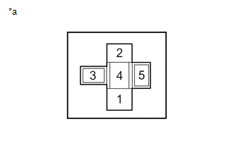
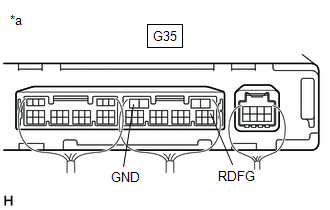
TERMINALS OF ECU
CHECK AIR CONDITIONING AMPLIFIER ASSEMBLY
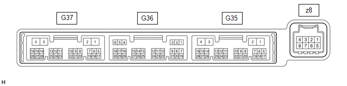
(a) Disconnect the G35 air conditioning amplifier assembly connector.
(b) Measure the voltage and resistance according to the value(s) in the table below.
HINT:
Measure the values on the wire harness side with the connector disconnected.
|
Terminal No. (Symbol) | Wiring Color |
Terminal Description | Condition |
Specified Condition |
|---|---|---|---|---|
|
G35-2 (IG+) - G35-4 (GND) |
LA-GR - W-B | Power source (IG) |
Power switch on (IG) |
11 to 14 V |
|
G35-2 (IG+) - G35-4 (GND) |
LA-GR - W-B | Power source (IG) |
Power switch off | Below 1 V |
|
G35-1 (B) - G35-4 (GND) |
LA-B - W-B | Auxiliary battery power supply |
Power switch off | 11 to 14 V |
|
G35-4 (GND) - Body ground |
W-B - Body ground | Ground |
Always | Below 1 Ω |
(c) Reconnect the G35 air conditioning amplifier assembly connector.
(d) Measure the voltage according to the value(s) in the table below.
|
Terminal No. (Symbol) | Wiring Color |
Terminal Description | Condition |
Specified Condition |
|---|---|---|---|---|
|
G35-5 (RDFG) - G35-4 (GND) |
L - W-B | Rear window defogger signal |
Power switch on (IG), rear window defogger switch off |
11 to 14 V |
|
G35-5 (RDFG) - G35-4 (GND) |
L - W-B | Rear window defogger signal |
Power switch on (IG), rear window defogger switch on |
Below 1 V |
CHECK REAR WINDOW DEFOGGER SWITCH (RADIO AND DISPLAY RECEIVER ASSEMBLY)
Click here 
Toyota Avalon (XX50) 2019-2022 Service & Repair Manual > Ua80e Automatic Transmission / Transaxle: Speed Sensor
ComponentsCOMPONENTS ILLUSTRATION *1 TRANSMISSION REVOLUTION SENSOR (NC) *2 TRANSMISSION REVOLUTION SENSOR (NT) *3 SPACER - - Tightening torque for "Major areas involving basic vehicle performance such as moving/turning/stopping": N*m (kgf*cm, ft.*lbf) - - InstallationINSTALLATION PROCEDURE 1. INST ...