Toyota Avalon (XX50) 2019-2022 Service & Repair Manual: Terminals Of Ecu

TERMINALS OF ECU

CHECK WINDSHIELD WIPER MOTOR ASSEMBLY

(a) Disconnect the A26 windshield wiper motor assembly connector.

(b) Measure the voltage and resistance on the wire harness side connector according to the value(s) in the table below.

Terminal No.

(Symbol)

Wiring Color

Terminal Description

Condition

Specified Condition

A26-1 (GND) - Body ground

W-B - Body ground

Ground

Always

Below 1 Ω

A26-4 (+B) - Body ground

SB - Body ground

Engine switch on (IG) signal (Power source circuit)

Engine switch on (IG)

11 to 14 V

Less than approximately 60 seconds after engine switch turned off

Approximately 60 seconds or more after engine switch turned off

Below 1 V

(c) Connect the A26 windshield wiper motor assembly connector.

HINT:

Since the A26 windshield wiper motor assembly connector is a waterproof type connector, the voltage and pulses cannot be checked directly. The values listed are for reference only.

(d) Measure the voltage and check for pulses according to the value(s) in the table below.

Terminal No.

(Symbol)

Wiring Color

Terminal Description

Condition

Specified Condition

A26-2 (LIN) - Body ground

R - Body ground

LIN communication signal

Engine switch on (IG)

Pulse generation

A26-3 (2S) - Body ground

B - Body ground

Windshield wiper motor assembly HI operation signal

Windshield wiper motor assembly stopped

4.8 to 5.2 V

Windshield wiper motor assembly operating in HI

Below 1 V

CHECK MAIN BODY ECU (MULTIPLEX NETWORK BODY ECU) AND INSTRUMENT PANEL JUNCTION BLOCK ASSEMBLY

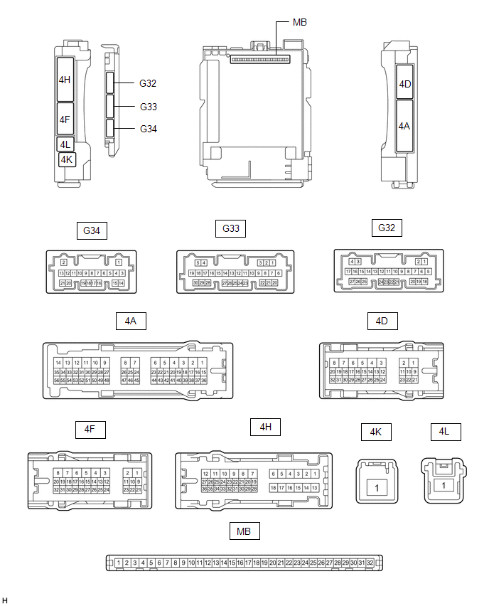
(a) Disconnect the instrument panel junction block assembly and main body ECU (multiplex network body ECU) connectors.

(b) Measure the voltage and resistance according to the value(s) in the table below.

Terminal No. (Symbol)

Wiring Color

Terminal Description

Condition

Specified Condition

4D-3 - Body ground

LA - Body ground

Ground

Always

Below 1 Ω

4F-1 - Body ground

LG - Body ground

Battery power supply

Always

11 to 14 V

4K-1 - Body ground

W - Body ground

Battery power supply

Always

11 to 14 V

(c) Connect the instrument panel junction block assembly and main body ECU (multiplex network body ECU) connectors.

(d) Measure the voltage and check for pulses according to the value(s) in the table below.

Terminal No. (Symbol)

Wiring Color

Terminal Description

Condition

Specified Condition

4F-2 - Body ground

R - Body ground

Washer circuit IG power source

Engine switch on (IG)

11 to 14 V

G32-3 (LIN3) - Body ground

BE - Body ground

LIN communication line

Engine switch on (IG)

Pulse generation

G32-12 (FWSR) - Body ground

L - Body ground

WASHER Relay operation signal

Engine switch on (IG), front washer switch off

11 to 14 V

Engine switch on (IG), front washer switch on

Below 2 V

G33-21 (WPS) - Body ground

LG - Body ground

WIPER Relay operation signal

Engine switch on (IG)

11 to 14 V

Less than approximately 60 seconds after engine switch turned off

Approximately 60 seconds or more after engine switch turned off

Below 1 V

CHECK COMBINATION METER ASSEMBLY

Click here

    System Diagram

    Utility

    See More:

    Toyota Avalon (XX50) 2019-2022 Service & Repair Manual > Power Window Control System(for Gasoline Model): Initialization
    INITIALIZATION INITIALIZE POWER WINDOW CONTROL SYSTEM (ALL DOORS) NOTICE: When any of the door window regulator sub-assemblies, power window regulator motor assemblies, door glass or door glass runs have been removed and reinstalled, the power window control system must be initialized. Functions suc ...

    Toyota Avalon (XX50) 2019-2022 Owners Manual

    Toyota Avalon (XX50) 2019-2022 Service & Repair Manual

    © 2024 Copyright www.tavalon.net
    0.0197