REMOVAL CAUTION / NOTICE / HINT The necessary procedures (adjustment, calibration, initialization, or registration) that must be performed after parts are removed and installed, or replaced during electrical key and tire pressure warning ECU and receiver removal/installation are shown below. Necessary Procedure After Parts Removed/Installed/Replaced (for Gasoline Model)
CAUTION: Some of these service operations affect the SRS airbag system. Read the precautionary notices concerning the SRS airbag system before servicing. 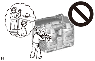 Click here
NOTICE: When replacing the electrical key and tire pressure warning ECU and receiver, read the transmitter IDs stored in the old ECU using the Techstream and write them down before removal. Click here
CAUTION: Some of these service operations affect the SRS airbag system. Read the precautionary notices concerning the SRS airbag system before servicing. Click here
NOTICE: When replacing the electrical key and tire pressure warning ECU and receiver, read the transmitter IDs stored in the old ECU using the Techstream and write them down before removal. Click here
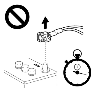
PROCEDURE 1. PRECAUTION NOTICE: After turning the engine switch (for Gasoline Model) or power switch (for HV Model) off, waiting time may be required before disconnecting the cable from the negative (-) auxiliary battery terminal. Therefore, make sure to read the disconnecting the cable from the negative (-) auxiliary battery terminal notices before proceeding with work. Click here
2. REMOVE LUGGAGE TRIM SERVICE HOLE COVER (for HV Model) Click here 3. REMOVE SPARE WHEEL COVER ASSEMBLY (w/ Seat Heater System) Click here 4. REMOVE LUGGAGE COMPARTMENT INNER TRIM PAD (w/ Seat Heater System) Click here 5. DISCONNECT CABLE FROM NEGATIVE AUXILIARY BATTERY TERMINAL for A25A-FXS: Click here for 2GR-FKS: Click here CAUTION:
 6. DISCONNECT REAR CENTER SEAT OUTER BELT ASSEMBLY Click here 7. REMOVE REAR SEAT CUSHION ASSEMBLY Click here 8. REMOVE REAR SEAT CUSHION LOCK HOOK Click here 9. REMOVE REAR SIDE SEATBACK ASSEMBLY RH HINT: Use the same procedure as for the LH side. Click here
10. DISCONNECT REAR DOOR OPENING TRIM WEATHERSTRIP RH HINT: Use the same procedure as for the LH side. Click here
11. REMOVE ROOF SIDE RAIL GARNISH ASSEMBLY RH HINT: Use the same procedure as for the LH side. Click here
12. REMOVE ROOF SIDE INNER GARNISH RH HINT: Use the same procedure as for the LH side. Click here
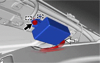
13. REMOVE ELECTRICAL KEY AND TIRE PRESSURE WARNING ECU AND RECEIVER NOTICE:
(b) Disengage the 2 guides. (c) Disconnect the connector to remove the electrical key and tire pressure warning ECU and receiver. | |||||||||||||||||||||||||||||||||||||||||||||||||||
Toyota Avalon (XX50) 2019-2022 Service & Repair Manual > Headup Display: Components
COMPONENTS ILLUSTRATION *1 DEFROSTER NOZZLE ASSEMBLY *2 METER MIRROR SUB-ASSEMBLY *3 METER MIRROR WIRE *4 NO. 1 SIDE DEFROSTER NOZZLE DUCT *5 NO. 2 SIDE DEFROSTER NOZZLE DUCT - - ...