DESCRIPTION
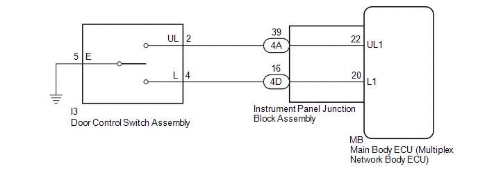
The main body ECU (multiplex network body ECU) receives switch signals from the door control switch assembly and activates the door lock motor on each door according to these signals.
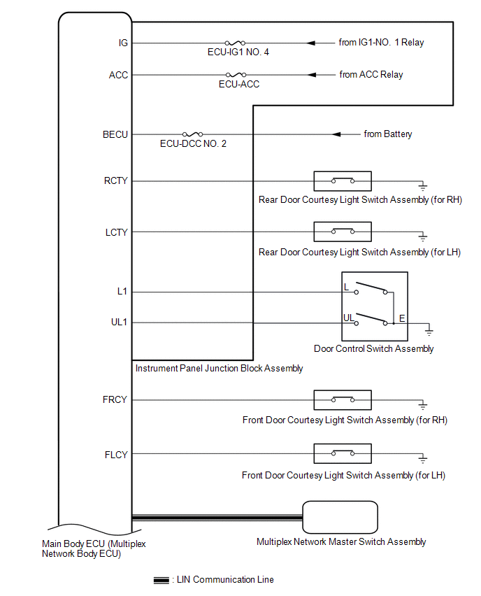
WIRING DIAGRAM
CAUTION / NOTICE / HINT
NOTICE:
Before replacing the main body ECU (multiplex network body ECU), refer to Registration.
Click here 
PROCEDURE
| 1. |
READ VALUE USING TECHSTREAM (Door Lock SW-Lock, Door Lock SW-Unlock) |
(a) Connect the Techstream to the DLC3.
(b) Turn the engine switch on (IG).
(c) Turn the Techstream on.
(d) Enter the following menus: Body Electrical / Main Body / Data List.
(e) Read the Data List according to the display on the Techstream.
Body Electrical > Main Body > Data List|
Tester Display | Measurement Item |
Range | Normal Condition |
Diagnostic Note |
|---|---|---|---|---|
|
Door Lock SW-Lock | Door control switch assembly lock signal |
OFF or ON | OFF: Lock side of door control switch assembly not pushed ON: Lock side of door control switch assembly pushed |
- |
| Door Lock SW-Unlock |
Door control switch assembly unlock signal |
OFF or ON | OFF: Unlock side of door control switch assembly not pushed ON: Unlock side of door control switch assembly pushed |
- |
|
Tester Display |
|---|
| Door Lock SW-Lock |
|
Door Lock SW-Unlock |
OK:
The Techstream indicates ON or OFF according to the switch operation shown in the table.
| OK |  | REPLACE MAIN BODY ECU (MULTIPLEX NETWORK BODY ECU) |
|
| 2. |
INSPECT DOOR CONTROL SWITCH ASSEMBLY |
(a) Remove the door control switch assembly.
Click here
(b) Inspect the door control switch assembly.
Click here
| NG | | REPLACE DOOR CONTROL SWITCH ASSEMBLY |
|
| 3. |
CHECK HARNESS AND CONNECTOR (DOOR CONTROL SWITCH ASSEMBLY - INSTRUMENT PANEL JUNCTION BLOCK ASSEMBLY AND BODY GROUND) |
(a) Disconnect the 4A and 4D instrument panel junction block assembly connectors.
(b) Measure the resistance according to the value(s) in the table below.
Standard Resistance:
|
Tester Connection | Condition |
Specified Condition |
|---|---|---|
|
I3-2 (UL) - 4A-39 | Always |
Below 1 Ω |
|
I3-4 (L) - 4D-16 | Always |
Below 1 Ω |
|
I3-5 (E) - Body ground |
Always | Below 1 Ω |
|
4A-39 or I3-2 (UL) - Body ground |
Always | 10 kΩ or higher |
|
4D-16 or I3-4 (L) - Body ground |
Always | 10 kΩ or higher |
| NG | | REPAIR OR REPLACE HARNESS OR CONNECTOR |
|
| 4. |
INSPECT INSTRUMENT PANEL JUNCTION BLOCK ASSEMBLY |
(a) Remove the instrument panel junction block assembly.
Click here
(b) Remove the main body ECU (multiplex network body ECU).
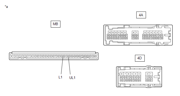
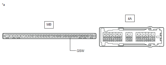
|
*a | Component without harness connected (Instrument Panel Junction Block Assembly) |
- | - |
(c) Measure the resistance according to the value(s) in the table below.
Standard Resistance:
|
Tester Connection | Condition |
Specified Condition |
|---|---|---|
|
MB-22 (UL1) - 4A-39 | Always |
Below 1 Ω |
|
MB-20 (L1) - 4D-16 | Always |
Below 1 Ω |
| OK | | REPLACE MAIN BODY ECU (MULTIPLEX NETWORK BODY ECU) |
| NG | | REPLACE INSTRUMENT PANEL JUNCTION BLOCK ASSEMBLY |
DESCRIPTION
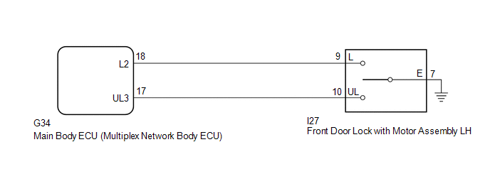
The main body ECU (multiplex network body ECU) receives switch signals from the door key lock and unlock switch (front door lock with motor assembly LH) and driver door key cylinder lock or unlock switch signals from the front door lock with motor assembly LH. The main body ECU (multiplex network body ECU) activates the door lock motor on each door according to these signals.
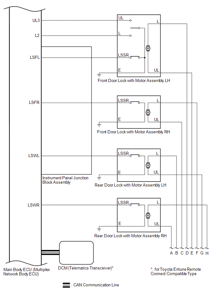
WIRING DIAGRAM
CAUTION / NOTICE / HINT
NOTICE:
Before replacing the main body ECU (multiplex network body ECU), refer to Registration.
Click here 
PROCEDURE
| 1. |
READ VALUE USING TECHSTREAM (Door Key SW-Lock, D Door Key SW-UL) |
(a) Connect the Techstream to the DLC3.
(b) Turn the engine switch on (IG).
(c) Turn the Techstream on.
(d) Enter the following menus: Body Electrical / Main Body / Data List.
(e) Read the Data List according to the display on the Techstream.
Body Electrical > Main Body > Data List|
Tester Display | Measurement Item |
Range | Normal Condition |
Diagnostic Note |
|---|---|---|---|---|
|
Door Key SW-Lock | Driver door key-linked lock / unlock switch lock signal |
OFF or ON | OFF: Driver door key cylinder not turned to lock position ON: Driver door key cylinder turned to lock position |
- |
| D Door Key SW-UL |
Driver door key-linked lock / unlock switch unlock signal |
OFF or ON | OFF: Driver door key cylinder not turned to unlock position ON: Driver door key cylinder turned to unlock position |
- |
|
Tester Display |
|---|
| Door Key SW-Lock |
|
D Door Key SW-UL |
| OK |  | REPLACE MAIN BODY ECU (MULTIPLEX NETWORK BODY ECU) |
|
| 2. |
INSPECT FRONT DOOR LOCK WITH MOTOR ASSEMBLY LH |
(a) Remove the front door lock with motor assembly LH.
Click here
(b) Inspect the front door lock with motor assembly LH.
Click here
| NG | | REPLACE FRONT DOOR LOCK WITH MOTOR ASSEMBLY LH |
|
| 3. |
CHECK HARNESS AND CONNECTOR (FRONT DOOR LOCK WITH MOTOR ASSEMBLY LH - MAIN BODY ECU (MULTIPLEX NETWORK BODY ECU) AND BODY GROUND) |
(a) Disconnect the G34 main body ECU (multiplex network body ECU) connector.
(b) Measure the resistance according to the value(s) in the table below.
Standard Resistance:
|
Tester Connection | Condition |
Specified Condition |
|---|---|---|
|
I27-9 (L) - G34-18 (L2) |
Always | Below 1 Ω |
|
I27-10 (UL) - G34-17 (UL3) |
Always | Below 1 Ω |
|
I27-7 (E) - Body ground |
Always | Below 1 Ω |
|
I27-9 (L) or G34-18 (L2) - Body ground |
Always | 10 kΩ or higher |
|
I27-10 (UL) or G34-17 (UL3) - Body ground |
Always | 10 kΩ or higher |
| OK | | REPLACE MAIN BODY ECU (MULTIPLEX NETWORK BODY ECU) |
| NG | | REPAIR OR REPLACE HARNESS OR CONNECTOR |
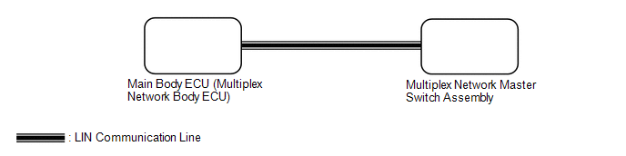
DESCRIPTION
The main body ECU (multiplex network body ECU) receives switch signals from the multiplex network master switch assembly and driver door key cylinder lock or unlock switch signals from the front door lock with motor assembly LH. The main body ECU (multiplex network body ECU) activates the door lock motor on each door according to these signals.
WIRING DIAGRAM
CAUTION / NOTICE / HINT
NOTICE:
Click here 
Click here
PROCEDURE
|
1. | CHECK FOR DTC (LIN COMMUNICATION SYSTEM) |
(a) Connect the Techstream to the DLC3.
(b) Turn the engine switch on (IG).
(c) Turn the Techstream on.
(d) Enter the following menus: Body Electrical / Main Body / Clear DTCs.
(e) Clear the DTCs.
Body Electrical > Main Body > Clear DTCs(f) Recheck for DTCs.
Body Electrical > Main Body > Trouble CodesOK:
DTC B1206 is not output.
| NG |  | GO TO LIN COMMUNICATION SYSTEM (DTC B1206) |
|
| 2. |
REPLACE MULTIPLEX NETWORK MASTER SWITCH ASSEMBLY |
(a) Replace the multiplex network master switch assembly.
Click here
|
| 3. |
CHECK DOOR LOCK OPERATION |
(a) Check that all doors can be locked and unlocked by the multiplex network master switch assembly.
Click here
OK:
All doors can be locked and unlocked by the multiplex network master switch assembly.
| OK | | END (MULTIPLEX NETWORK MASTER SWITCH ASSEMBLY WAS DEFECTIVE) |
| NG | | REPLACE MAIN BODY ECU (MULTIPLEX NETWORK BODY ECU) |
DESCRIPTION
If the collision door lock release function does not operate normally, or an open or short in the GSW input circuit of the main body ECU (multiplex network body ECU) is detected, DTC B1243 will be stored.
HINT:
If DTC B1243 is stored, the automatic door lock function, and collision door lock release function will be prohibited.
|
DTC No. | Detection Item |
DTC Detection Condition | Trouble Area |
|---|---|---|---|
|
B1243 | GSW Terminal Circuit Malfunction |
A malfunction occurs in the GSW input circuit of the main body ECU (multiplex network body ECU). |
|
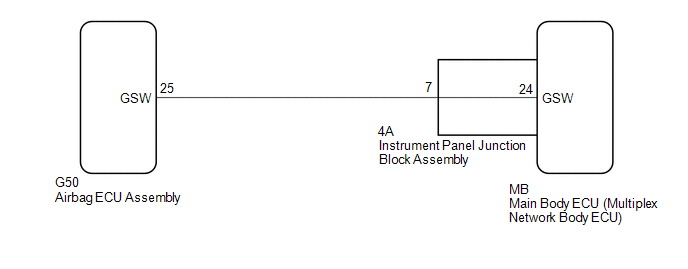
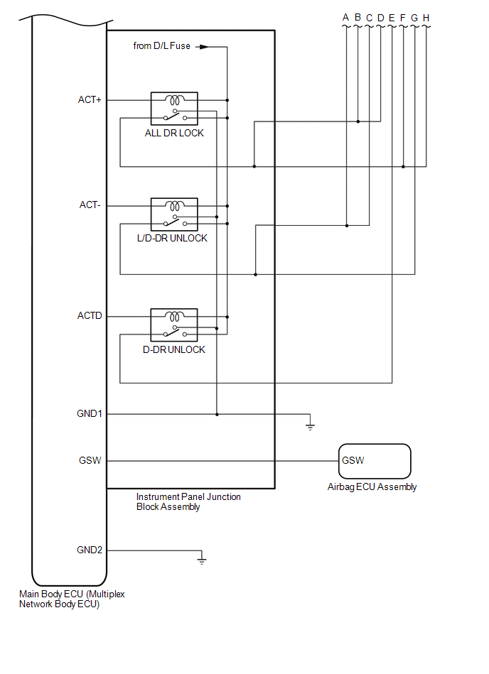
WIRING DIAGRAM
CAUTION / NOTICE / HINT
NOTICE:
Click here 
Click here
PROCEDURE
|
1. | CHECK DTC OUTPUT |
(a) Connect the Techstream to the DLC3.
(b) Turn the engine switch on (IG).
(c) Turn the Techstream on.
(d) Enter the following menus: Body Electrical / Main Body / Trouble Codes.
(e) Clear the DTCs.
Body Electrical > Main Body > Clear DTCs(f) Recheck for DTCs.
Body Electrical > Main Body > Trouble CodesOK:
DTC B1243 is not output.
| OK |  | USE SIMULATION METHOD TO CHECK |
|
| 2. |
CHECK MAIN BODY ECU (MULTIPLEX NETWORK BODY ECU) (GSW VOLTAGE) |
(a) Disconnect the cable from the negative (-) battery terminal.
CAUTION:
Wait at least 90 seconds after disconnecting the cable from the negative (-) battery terminal to disable the SRS system.
NOTICE:
Turning the engine switch on (IG) with the airbag ECU assembly connector disconnected causes other DTCs to be stored. Clear the DTCs after performing this inspection.
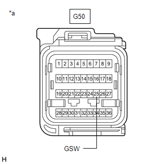
(b) Disconnect the G50 airbag ECU assembly connector.
(c) Connect the cable to the negative (-) battery terminal.
| (d) Measure the voltage according to the value(s) in the table below. Standard Voltage:
|
|
| NG | | GO TO STEP 5 |
|
| 3. |
REPLACE AIR BAG ECU ASSEMBLY |
(a) Disconnect the cable from the negative (-) battery terminal.
CAUTION:
Wait at least 90 seconds after disconnecting the cable from the negative (-) battery terminal to disable the SRS system.
(b) Replace the airbag ECU assembly.
Click here
|
| 4. |
CHECK DTC OUTPUT |
(a) Clear the DTCs.
Body Electrical > Main Body > Clear DTCs(b) Recheck for DTCs.
Body Electrical > Main Body > Trouble CodesOK:
DTC B1243 is not output.
| OK | | END (AIRBAG ECU ASSEMBLY WAS DEFECTIVE) |
| NG | | REPLACE MAIN BODY ECU (MULTIPLEX NETWORK BODY ECU) |
| 5. |
CHECK HARNESS AND CONNECTOR (AIRBAG ECU ASSEMBLY - INSTRUMENT PANEL JUNCTION BLOCK ASSEMBLY) |
(a) Disconnect the cable from the negative (-) battery terminal.
CAUTION:
Wait at least 90 seconds after disconnecting the cable from the negative (-) battery terminal to disable the SRS system.
(b) Disconnect the 4A instrument panel junction block assembly connector.
(c) Measure the resistance according to the value(s) in the table below.
Standard Resistance:
|
Tester Connection | Condition |
Specified Condition |
|---|---|---|
|
G50-25 (GSW) - 4A-7 | Always |
Below 1 Ω |
|
4A-7 or G50-25 (GSW) - Other terminals and body ground |
Always | 10 kΩ or higher |
| NG | | REPAIR OR REPLACE HARNESS OR CONNECTOR |
|
| 6. |
INSPECT INSTRUMENT PANEL JUNCTION BLOCK ASSEMBLY |
(a) Remove the instrument panel junction block assembly.
Click here
(b) Remove the main body ECU (multiplex network body ECU).
|
*a | Component without harness connected (Instrument Panel Junction Block Assembly) |
- | - |
(c) Measure the resistance according to the value(s) in the table below.
Standard Resistance:
|
Tester Connection | Condition |
Specified Condition |
|---|---|---|
|
MB-24 (GSW) - 4A-7 | Always |
Below 1 Ω |
| OK | | REPLACE MAIN BODY ECU (MULTIPLEX NETWORK BODY ECU) |
| NG | | REPLACE INSTRUMENT PANEL JUNCTION BLOCK ASSEMBLY |
CHECK FOR INTERMITTENT PROBLEMS
NOTICE:
Operation History
HINT:
The main body ECU (multiplex network body ECU) stores Operation History, which can be read using the Techstream, when a malfunction of the power door lock control system occurs.
(a) Connect the Techstream to the DLC3.
(b) Turn the engine switch on (IG).
(c) Turn the Techstream on.
(d) Enter the following menus: Body Electrical / Main Body / Utility / Operation History.
Body Electrical > Main Body > Utility|
Tester Display |
|---|
| Operation History |
(e) According to the display on the Techstream, read and save the operation history.
|
Operation History List |
|---|
|
Manual Lock |
|
Door Key Linked Lock |
|
Wireless Lock |
|
Wireless Auto Lock (30s) |
|
Wireless Double Lock Set |
|
Auto Entry Lock |
|
Auto Entry Double Lock Set |
|
Auto Entry Lock (30s) |
|
Power Back Door Lock signal by Back Door Control Switch |
|
Shift Linked Auto Lock |
|
Vehicle Speed Linked Auto Lock (North America) |
|
Security Forced Lock |
|
Auto Lock Switch Answerback Lock |
|
Door Lock by Active Test |
|
Accessory Auto Lock |
|
Remote Door Lock |
|
Door Lock by A/C |
|
Manual Unlock |
|
D-Seat Key Linked Unlock (Twice) |
|
Door Key Linked Unlock |
|
Wireless Unlock (Twice) |
|
Wireless Unlock |
|
Accessory Auto Entry Unlock |
|
Auto Entry Unlock |
|
Auto Entry Preparation Unlock |
|
Unlock by kick Sensor Input |
|
Key in Vehicle Detected Unlock |
|
Key Detected Unlock 1 |
|
Key Detected Unlock 2 |
|
Key Detected Unlock 3 |
|
Unlock by Emblem Sensor Input |
|
Urgent Stop Support Unlock |
|
Shift Linked Auto Unlock |
|
Door Open/Close Linked Auto Unlock |
|
Shock Detection Unlock |
|
Door Unlock by Active Test |
|
Accessory Auto Unlock |
|
Auto Lock Switch Answerback Unlock |
|
Remote Door Unlock |
|
One Motion PBD Open/Stop judgment during the closing operation |
|
Unlock by kick Sensor Input |
|
One Motion PSD Open/Stop judgment during the closing operation |
|
Fail Safe Unset |
HINT:
Depending on the specifications of the vehicle some items may not be displayed.
Symptom Simulation
Click here 
CUSTOMIZE PARAMETERS
CUSTOMIZE POWER DOOR LOCK CONTROL SYSTEM
HINT:
The following items can be customized.
NOTICE:
(a) Customizing with the Techstream
(1) Connect the Techstream to the DLC3.
(2) Turn the engine switch on (IG).
(3) Turn the Techstream on.
(4) Enter the following menus: Customize Setting / Door Lock.
(5) Select the setting by referring to the table below.
Door Lock|
Tester Display | Description |
Default | Setting |
ECU |
|---|---|---|---|---|
| Unlock Key Twice |
Function that unlocks only the driver door when the driver door key cylinder is turned to unlock once, and unlocks all doors when it is turned to unlock twice. For the OFF setting, turning it once unlocks all doors. |
ON | 0:OFF,1:ON |
Main body ECU (Multiplex network body ECU) |
|
Automatic Door Lock Function |
| Link Shift |
00:OFF,01:Link Shift,10:Link Speed |
Main body ECU (Multiplex network body ECU) |
|
Automatic Door Unlock Function |
| Link Shift |
00:OFF,01:Link D-door,10:Link Shift |
Main body ECU (Multiplex network body ECU) |
(b) Customizing with the multi-display
(1) Turn the engine switch on (IG).
(2) Enter the following menus: MENU / Setup / Vehicle / Vehicle Customization / Door Lock Settings.
(3) Select the setting by referring to the table below.
|
Display | Description |
Default | Setting |
Relevant ECU |
|---|---|---|---|---|
| Automatic Door Lock |
| By Shift from P |
By Speed, By Shift from P or Off |
Main body ECU (Multiplex network body ECU) |
|
Automatic Door Unlock |
| By Shift to P |
By Shift to P, By Driver Door or Off |
Main body ECU (Multiplex network body ECU) |
DATA LIST / ACTIVE TEST
DATA LIST
HINT:
Using the Techstream to read the Data List allows the values or states of switches, sensors, actuators and other items to be read without removing any parts. This non-intrusive inspection can be very useful because intermittent conditions or signals may be discovered before parts or wiring is disturbed. Reading the Data List information early in troubleshooting is one way to save diagnostic time.
NOTICE:
In the table below, the values listed under "Normal Condition" are reference values. Do not depend solely on these reference values when deciding whether a part is faulty or not.
(a) Connect the Techstream to the DLC3.
(b) Turn the engine switch on (IG).
(c) Turn the Techstream on.
(d) Enter the following menus: Body Electrical / Main Body or Master Switch / Data List.
(e) Read the Data List according to the display on the Techstream.
Body Electrical > Main Body > Data List|
Tester Display | Measurement Item |
Range | Normal Condition |
Diagnostic Note |
|---|---|---|---|---|
|
ACC SW | Engine switch on (ACC) signal |
OFF or ON | OFF: Engine switch off ON: Engine switch on (ACC) |
- |
| IG SW |
Engine switch on (IG) signal |
OFF or ON | OFF: Engine switch off or on (ACC) ON: Engine switch on (IG) |
- |
| RR Door Courtesy SW |
Rear door courtesy light switch (for RH) signal |
OFF or ON | OFF: Rear door RH closed ON: Rear door RH open |
- |
| RL Door Courtesy SW |
Rear door courtesy light switch (for LH) signal |
OFF or ON | OFF: Rear door LH closed ON: Rear door LH open |
- |
| Door Lock SW-Lock |
Door control switch assembly lock signal |
OFF or ON | OFF: Lock side of door control switch assembly not pushed ON: Lock side of door control switch assembly pushed |
- |
| Door Lock SW-Unlock |
Door control switch assembly unlock signal |
OFF or ON | OFF: Unlock side of door control switch assembly not pushed ON: Unlock side of door control switch assembly pushed |
- |
| Door Key SW-Lock |
Driver door key-linked lock / unlock switch lock signal |
OFF or ON | OFF: Driver door key cylinder not turned to lock position ON: Driver door key cylinder turned to lock position |
- |
| D Door Key SW-UL |
Driver door key-linked lock / unlock switch unlock signal |
OFF or ON | OFF: Driver door key cylinder not turned to unlock position ON: Driver door key cylinder turned to unlock position |
- |
| FR Door Lock Pos |
Front door RH unlock detection switch signal |
LOCK or UNLOCK | LOCK: Front door RH locked UNLOCK: Front door RH unlocked |
- |
| FR Door Courtesy SW |
Front door courtesy light switch (for RH) signal |
OFF or ON | OFF: Front door RH closed ON: Front door RH open |
- |
| FL Door Lock Pos |
Front door LH unlock detection switch signal |
LOCK or UNLOCK | LOCK: Front door LH locked UNLOCK: Front door LH unlocked |
- |
| FL Door Courtesy SW |
Front door courtesy light switch (for LH) signal |
OFF or ON | OFF: Front door LH closed ON: Front door LH open |
- |
| RR-Door Lock Pos SW |
Rear door RH unlock detection switch signal |
OFF or ON | OFF: Rear door RH locked ON: Rear door RH unlocked |
- |
| RL-Door Lock Pos SW |
Rear door LH unlock detection switch signal |
OFF or ON | OFF: Rear door LH locked ON: Rear door LH unlocked |
- |
| Unlock Key Twice |
Key-linked 2-step unlock function |
OFF or ON | Customize setting displayed |
- |
| Automatic Door Lock Function |
Automatic door lock function |
OFF, Link Shift or Link Speed |
Customize setting displayed |
- |
| Automatic Door Unlock Function |
Automatic door unlock function |
OFF, Link D-door or Link Shift |
Customize setting displayed |
- |
| The Number of DTC |
Number of trouble codes |
0 to 255 | Number of stored DTCs displayed |
- |
|
Tester Display | Measurement Item |
Range | Normal Condition |
Diagnostic Note |
|---|---|---|---|---|
|
Door Lock Switch Status |
Multiplex network master switch assembly lock signal |
OFF or ON | OFF: Lock side of multiplex network master switch assembly not pushed ON: Lock side of multiplex network master switch assembly pushed |
- |
| Door Unlock Switch Status |
Multiplex network master switch assembly unlock signal |
OFF or ON | OFF: Unlock side of multiplex network master switch assembly not pushed ON: Unlock side of multiplex network master switch assembly pushed |
- |
ACTIVE TEST
HINT:
Using the Techstream to perform Active Tests allows relays, VSVs, actuators and other items to be operated without removing any parts. This non-intrusive functional inspection can be very useful because intermittent operation may be discovered before parts or wiring is disturbed. Performing Active Tests early in troubleshooting is one way to save diagnostic time. Data List information can be displayed while performing Active Tests.
(a) Connect the Techstream to the DLC3.
(b) Turn the engine switch on (IG).
(c) Turn the Techstream on.
(d) Enter the following menus: Body Electrical / Main Body / Active Test.
(e) Perform the Active Test according to the display on the Techstream.
Body Electrical > Main Body > Active Test|
Tester Display | Measurement Item |
Control Range | Diagnostic Note |
|---|---|---|---|
|
Door Lock | Door lock motor |
OFF/Unlock/Lock | - |
|
D-Door Unlock | Driver door lock motor |
OFF/ON | - |
|
Shock Detection Unlock |
Operate door lock motor |
UNLOCK/LOCK | - |
DIAGNOSTIC TROUBLE CODE CHART
Power Door Lock Control System (for Gasoline Model)|
DTC No. | Detection Item |
Link |
|---|---|---|
| B1243 |
GSW Terminal Circuit Malfunction |
|
DTC CHECK / CLEAR
CHECK DTC
(a) Connect the Techstream to the DLC3.
(b) Turn the engine switch on (IG).
(c) Turn the Techstream on.
(d) Enter the following menus: Body Electrical / Main Body / Trouble Codes.
Body Electrical > Main Body > Trouble Codes(e) Check the details of the DTCs.
Click here

CLEAR DTC
(a) Connect the Techstream to the DLC3.
(b) Turn the engine switch on (IG).
(c) Turn the Techstream on.
(d) Enter the following menus: Body Electrical / Main Body / Trouble Codes.
Body Electrical > Main Body > Clear DTCs(e) Clear the DTCs.
CAUTION / NOTICE / HINT
HINT:
PROCEDURE
|
1. | VEHICLE BROUGHT TO WORKSHOP |
|
| 2. |
CUSTOMER PROBLEM ANALYSIS CHECK |
HINT:
| What |
Vehicle model, system name |
| When |
Date, time, occurrence frequency, whether the problem occurred recently or has been occurring for a long time |
|
Where | Whether the problem occurs at a specific location |
|
Under what conditions? | Whether the doors were locked or unlocked, whether the engine switch was on (IG), whether the engine has started. |
|
How did it happen? | Problem symptoms |
|
| 3. |
READ AND SAVE OPERATION HISTORY |
NOTICE:
(a) Read and save operation history using the Techstream.
Click here

|
Tester Display |
|---|
| Operation History |
|
| 4. |
PRE-CHECK |
(a) Measure the battery voltage.
Standard Voltage:
11 to 14 V
If the voltage is below 11 V, recharge or replace the battery before proceeding to the next step.
(b) Check the fuses and relays.
(c) Check the connector connections and terminals to make sure that there are no abnormalities such as loose connections, deformation, etc.
|
| 5. |
CHECK COMMUNICATION FUNCTION OF CAN COMMUNICATION SYSTEM* |
(a) Using the Techstream, check for CAN communication system DTCs.
Click here
|
Result | Proceed to |
|---|---|
|
CAN DTCs are not output |
A |
| CAN DTCs are output |
B |
| B |
 | GO TO CAN COMMUNICATION SYSTEM |
|
| 6. |
CHECK COMMUNICATION FUNCTION OF LIN COMMUNICATION SYSTEM* |
(a) Using the Techstream, check for LIN communication system DTCs.
Click here
|
Result | Proceed to |
|---|---|
|
LIN DTCs are not output |
A |
| LIN DTCs are output |
B |
| B |
| GO TO LIN COMMUNICATION SYSTEM |
|
| 7. |
CHECK FOR DTC (MULTIPLEX NETWORK MASTER SWITCH ASSEMBLY)* |
(a) Clear the DTCs.
Click here
(b) Recheck for DTCs.
Body Electrical > Master Switch > Trouble Codes|
Result | Proceed to |
|---|---|
|
DTC B2312 is not output |
A |
| DTC B2312 is output |
B |
| B |
| GO TO POWER WINDOW CONTROL SYSTEM |
|
| 8. |
CHECK FOR DTC (MAIN BODY ECU (MULTIPLEX NETWORK BODY ECU))* |
(a) Clear the DTCs.
Click here
(b) Recheck for DTCs.
Body Electrical > Main Body > Trouble Codes|
Result | Proceed to |
|---|---|
|
DTC B1243 is not output |
A |
| DTC B1243 is output |
B |
| B |
| GO TO DIAGNOSTIC TROUBLE CODE CHART |
|
| 9. |
PROBLEM SYMPTOMS TABLE |
(a) Refer to Problem Symptoms Table.
Click here
|
Result | Proceed to |
|---|---|
|
Fault is not listed in Problem Symptoms Table (Fault can be simulated) |
A |
| Fault is not listed in Problem Symptoms Table (Fault cannot be simulated) |
B |
| Fault is listed in Problem Symptoms Table |
C |
| B |
| CHECK FOR INTERMITTENT PROBLEMS |
| C |
| GO TO STEP 11 |
|
| 10. |
OVERALL ANALYSIS AND TROUBLESHOOTING* |
(a) Terminals of ECU
Click here
(b) Data List / Active Test
Click here
(c) Operation Check
Click here
(d) Inspection
|
| 11. |
REPAIR OR REPLACE |
|
| 12. |
CONFIRMATION TEST |
| NEXT | | END |
DESCRIPTION
In cases where the doors locked or unlocked by themselves even though a door lock or unlock operation was not performed, a vehicle malfunction, accidental operation by the customer or a passenger, or environmental factors should all be considered as a possible cause. By using the operation history, the possible causes of the malfunction can be narrowed down, enabling the problem to be solved by repair or replacement, or by explaining to the customer how environmental factors affect the operation.
CAUTION / NOTICE / HINT
NOTICE:
PROCEDURE
|
1. | CONFIRM VEHICLE CONDITION |
(a) Confirm the vehicle symptoms.
|
Result | Proceed to |
|---|---|
|
Doors locked unintentionally |
A |
| Doors unlocked unintentionally |
B |
| B |
 | GO TO STEP 5 |
|
| 2. |
CHECK LOCK OPERATION HISTORY |
(a) Use the Techstream to check the door lock operation history around the time the customer reported the malfunction to have occurred.
(1) Connect the Techstream to the DLC3.
(2) Turn the engine switch on (IG).
(3) Turn the Techstream on.
(4) Enter the following menus: Body Electrical / Main Body / Utility / Operation History.
Body Electrical > Main Body > Utility|
Tester Display |
|---|
| Operation History |
(5) Read the Operation History according to the display on the Techstream.
(6) Check if there is operation history around the time that the customer reported the malfunction to have occurred, and perform an operation check.
Click here 
|
Result | Proceed to |
|---|---|
|
There is operation history around the time that the customer reported the malfunction to have occurred, but a malfunction could not be identified during the operation check. | A |
|
There is operation history around the time that the customer reported the malfunction to have occurred, and the malfunction was identified during the operation check. | B |
|
There is no operation history around the time that the customer reported the malfunction to have occurred. |
C |
| B |
| END (VEHICLE MALFUNCTION) |
| C |
| GO TO STEP 4 |
|
| 3. |
INTERVIEW THE CUSTOMER |
(a) If the problem symptoms could not be reproduced, explain to the customer the details of the door lock operation history such as the signal timings of the multiplex network master switch assembly, key, etc.
Click here
OK:
Cause was identified
| OK | | END |
| NG | | CHECK FOR INTERMITTENT PROBLEMS |
| 4. |
CHECK UNLOCK OPERATION HISTORY |
(a) Use the Techstream to check the door unlock operation history around the time the customer reported the malfunction to have occurred.
(1) Connect the Techstream to the DLC3.
(2) Turn the engine switch on (IG).
(3) Turn the Techstream on.
(4) Enter the following menus: Body Electrical / Main Body / Utility / Operation History.
Body Electrical > Main Body > Utility|
Tester Display |
|---|
| Operation History |
(5) Read the Operation History according to the display on the Techstream.
(6) Check if there is operation history around the time that the customer reported the malfunction to have occurred, and perform an operation check.
Click here
|
Result | Proceed to |
|---|---|
|
There is no operation history around the time that the customer reported the malfunction to have occurred. |
A |
| There is operation history around the time that the customer reported the malfunction to have occurred, but a malfunction could not be identified during the operation check. | |
| There is operation history around the time that the customer reported the malfunction to have occurred, and the malfunction was identified during the operation check. | B |
| A |
| CHECK FOR INTERMITTENT PROBLEMS |
| B |
| END |
| 5. |
CHECK UNLOCK OPERATION HISTORY |
(a) Use the Techstream to check the door unlock operation history around the time the customer reported the malfunction to have occurred.
(1) Connect the Techstream to the DLC3.
(2) Turn the engine switch on (IG).
(3) Turn the Techstream on.
(4) Enter the following menus: Body Electrical / Main Body / Utility / Operation History.
Body Electrical > Main Body > Utility|
Tester Display |
|---|
| Operation History |
(5) Read the Operation History according to the display on the Techstream.
(6) Check if there is operation history around the time that the customer reported the malfunction to have occurred, and perform an operation check.
Click here
|
Result | Proceed to |
|---|---|
|
There is operation history around the time that the customer reported the malfunction to have occurred, but a malfunction could not be identified during the operation check. | A |
|
There is operation history around the time that the customer reported the malfunction to have occurred, and the malfunction was identified during the operation check. | B |
|
There is no operation history around the time that the customer reported the malfunction to have occurred. |
C |
| B |
| END |
| C |
| GO TO STEP 7 |
|
| 6. |
INTERVIEW THE CUSTOMER |
(a) If the problem symptoms could not be reproduced, explain to the customer the details of the door lock operation history such as the signal timings of the multiplex network master switch assembly, key, etc.
Click here
OK:
Cause was identified
| OK | | END |
| NG | | CHECK FOR INTERMITTENT PROBLEMS |
| 7. |
CHECK LOCK OPERATION HISTORY |
(a) Use the Techstream to check the door lock operation history around the time the customer reported the malfunction to have occurred.
(1) Connect the Techstream to the DLC3.
(2) Turn the engine switch on (IG).
(3) Turn the Techstream on.
(4) Enter the following menus: Body Electrical / Main Body / Utility / Operation History.
Body Electrical > Main Body > Utility|
Tester Display |
|---|
| Operation History |
(5) Read the Operation History according to the display on the Techstream.
(6) Check if there is operation history around the time that the customer reported the malfunction to have occurred, and perform an operation check.
Click here
|
Result | Proceed to |
|---|---|
|
There is no operation history around the time that the customer reported the malfunction to have occurred. |
A |
| There is operation history around the time that the customer reported the malfunction to have occurred, but a malfunction could not be identified during the operation check. | |
| There is operation history around the time that the customer reported the malfunction to have occurred, and the malfunction was identified during the operation check. | B |
| A |
| CHECK FOR INTERMITTENT PROBLEMS |
| B |
| END |
OPERATION CHECK
CHECK CUSTOMIZE PARAMETERS
NOTICE:
The operation check below is based on the non-customized initial condition of the vehicle.
Click here 
CHECK BASIC FUNCTIONS
(a) Check that all of the doors lock when the lock side of the door control switch is pressed.
(b) Check that all of the doors unlock when the unlock side of the door control switch is pressed.
(c) Check that all of the doors lock when the driver door key cylinder is turned to lock using the mechanical key.
(d) Check that only the driver door unlocks when the driver door lock cylinder is turned to unlock once using the key and all of the doors unlock when it is turned to unlock again.
CHECK THE KEY LOCK-IN PREVENTION FUNCTION
NOTICE:
In order to prevent the key from being locked in the vehicle, the following inspection should be performed with the driver door window open.
(a) Turn the engine switch on (IG) or on (ACC).
(b) With the driver door open, check that all of the doors unlock immediately after the door lock knob for the driver door is pressed.
(c) With the driver door open, check that all of the doors unlock immediately after the lock side of the door control switch is pressed.
(d) With the driver door open, press the driver door lock knob and hold it for 2 seconds or more, then close the driver door and check that all of the doors unlock.
CHECK THE SECURITY FUNCTION OF THE DOOR LOCK CONTROL SYSTEM
(a) Close all of the doors and leave the driver door window open so that the door control switch can be operated from outside the vehicle. (Step 1)
(b) Open the driver door and remove the key from the vehicle. With the door still open, lock the door using the door lock knob. Close the driver door. Then, check that the doors do not unlock when the unlock side of the door control switch is pressed from outside the vehicle.
(c) Starting from Step 1, with the key outside the vehicle, close and lock the driver door using the mechanical key. Then, check that the doors do not unlock when the unlock side of the door control switch is pressed from outside the vehicle.
(d) Starting from Step 1, with the key outside the vehicle, close and lock the driver door using wireless key operation or smart key operation. Then, check that the doors do not unlock when the unlock side of the door control switch is pressed from outside the vehicle.
HINT:
Check that the security function of the door lock control system is canceled under the following conditions:
CHECK THE KEY-LINKED 2-STEP UNLOCK FUNCTION
HINT:
The key-linked 2-step unlock function can be customized. Make sure that function is ON before this procedure.
Click here
(a) Lock all doors.
(b) Check that only the driver door unlocks when the driver door lock cylinder is turned to unlock once using the key and all of the doors unlock when it is turned to unlock again.
CHECK THE SHIFT LINKED AUTOMATIC DOOR LOCK FUNCTION
HINT:
The shift linked automatic door lock function can be customized. Make sure that function is ON before this procedure.
Click here
(a) With the shift lever in P and the engine switch on (IG), check that all doors lock automatically when the shift lever is moved to any position other than P.
CHECK THE SPEED-SENSITIVE AUTOMATIC DOOR LOCK FUNCTION
HINT:
The speed-sensitive automatic door lock function can be customized. Make sure that function is ON before this procedure.
Click here
(a) When any door is unlocked and the vehicle is driven at approximately 20 km/h (12 mph) or more, check that all of the doors lock automatically.
CHECK THE SHIFT LINKED AUTOMATIC DOOR UNLOCK FUNCTION
HINT:
The shift linked automatic door unlock function can be customized. Make sure that function is ON before this procedure.
Click here
(a) With the shift lever in any position other than P and the engine switch on (IG), check that all doors unlock automatically when the shift lever is moved to P.
CHECK THE DRIVER DOOR-LINKED AUTOMATIC DOOR UNLOCK FUNCTION
HINT:
The driver door-linked automatic door unlock function can be customized. Make sure that function is ON before this procedure.
Click here
(a) When the driver door is closed, turning the engine switch from on (IG) to off and opening the driver door within approximately 43 seconds will automatically unlock all doors.
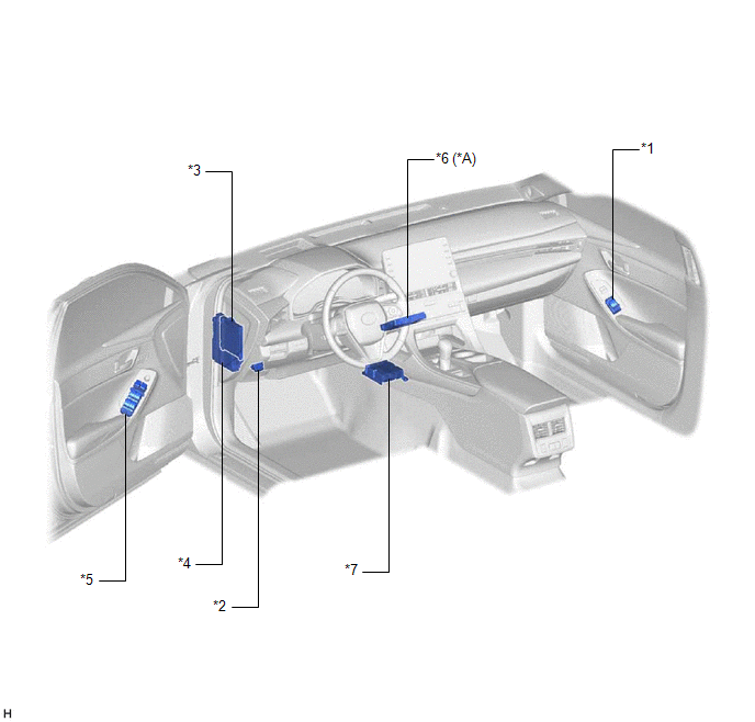
PARTS LOCATION
ILLUSTRATION
|
*A | for Toyota Entune Remote Connect Compatible Type |
- | - |
|
*1 | DOOR CONTROL SWITCH ASSEMBLY |
*2 | DLC3 |
|
*3 | MAIN BODY ECU (MULTIPLEX NETWORK BODY ECU) |
*4 | INSTRUMENT PANEL JUNCTION BLOCK ASSEMBLY - ECU-IG1 NO. 4 FUSE - ECU-ACC FUSE - ECU-DCC NO. 2 FUSE - ALL DR LOCK RELAY - L/D-DR UNLOCK RELAY - D-DR UNLOCK RELAY |
|
*5 | MULTIPLEX NETWORK MASTER SWITCH ASSEMBLY - DOOR CONTROL SWITCH |
*6 | DCM (TELEMATICS TRANSCEIVER) |
|
*7 | AIRBAG ECU ASSEMBLY |
- | - |
ILLUSTRATION

|
*1 | FRONT DOOR COURTESY LIGHT SWITCH ASSEMBLY (for LH) |
*2 | FRONT DOOR COURTESY LIGHT SWITCH ASSEMBLY (for RH) |
|
*3 | FRONT DOOR LOCK WITH MOTOR ASSEMBLY LH |
*4 | FRONT DOOR LOCK WITH MOTOR ASSEMBLY RH |
|
*5 | REAR DOOR COURTESY LIGHT SWITCH ASSEMBLY (for LH) |
*6 | REAR DOOR COURTESY LIGHT SWITCH ASSEMBLY (for RH) |
|
*7 | REAR DOOR LOCK WITH MOTOR ASSEMBLY LH |
*8 | REAR DOOR LOCK WITH MOTOR ASSEMBLY RH |
|
*9 | DOOR KEY LOCK AND UNLOCK SWITCH |
*10 | DOOR LOCK MOTOR |
|
*11 | DOOR UNLOCK DETECTION SWITCH |
- | - |
PRECAUTION
PRECAUTION FOR DISCONNECTING CABLE FROM NEGATIVE BATTERY TERMINAL
NOTICE:
When disconnecting the cable from the negative (-) battery terminal, initialize the following systems after the cable is reconnected.
|
System Name | See Procedure |
|---|---|
|
Lane Departure Alert System (w/ Steering Control) |
|
|
Intelligent Clearance Sonar System | |
|
Parking Assist Monitor System | |
|
Panoramic View Monitor System | |
|
Pre-collision System | |
|
Lighting System (for Gasoline Model with Cornering Light) |
PRECAUTION FOR REGISTRATION
(a) Before replacing the main body ECU (multiplex network body ECU), refer to Registration.
Click here 
PROBLEM SYMPTOMS TABLE
HINT:
|
Symptom | Suspected Area |
Link |
|---|---|---|
| Only driver door LOCK functions do not operate |
Front door lock with motor assembly LH |
|
|
Wire harness or connector |
- | |
| Instrument panel junction block assembly |
- | |
|
Only driver door UNLOCK functions do not operate |
Front door lock with motor assembly LH |
|
|
Wire harness or connector |
- | |
| Main body ECU (Multiplex network body ECU) |
- | |
| Instrument panel junction block assembly |
- | |
|
Only front passenger door LOCK/UNLOCK functions do not operate |
Front door lock with motor assembly RH |
|
|
Wire harness or connector |
- | |
| Instrument panel junction block assembly |
- | |
| Only rear door LH LOCK/UNLOCK functions do not operate. |
Rear door lock with motor assembly LH |
|
|
Wire harness or connector |
- | |
| Instrument panel junction block assembly |
- | |
| Only rear door RH LOCK/UNLOCK functions do not operate. |
Rear door lock with motor assembly RH |
|
|
Wire harness or connector |
- | |
| Instrument panel junction block assembly |
- | |
|
All doors LOCK/UNLOCK functions do not operate via door key cylinder |
Main body ECU (Multiplex network body ECU) |
|
|
Front door lock with motor assembly LH | ||
|
Wire harness or connector | ||
|
All doors LOCK/UNLOCK functions do not operate via master switch |
Lin communication system |
|
|
Multiplex network master switch assembly | ||
|
Main body ECU (Multiplex network body ECU) | ||
|
All doors LOCK/UNLOCK functions do not operate via door control switch |
Main body ECU (Multiplex network body ECU) |
|
|
Door control switch assembly | ||
|
Wire harness or connector | ||
|
Instrument panel junction block assembly | ||
|
All doors LOCK/UNLOCK functions do not operate via multiplex network master switch assembly and door key cylinder. |
Instrument panel junction block assembly |
- |
| Main body ECU (Multiplex network body ECU) |
- | |
|
Speed-sensitive automatic door lock function does not operate (meter/gauge system operates normally). |
CAN communication system |
|
|
Main body ECU (Multiplex network body ECU) |
| |
|
Shift-linked automatic door lock/unlock functions do not operate (automatic transaxle system operates normally). |
CAN communication system |
|
|
Main body ECU (Multiplex network body ECU) |
| |
|
ECM |
| |
|
Key lock-in prevention function does not operate |
Instrument panel junction block assembly |
|
|
Main body ECU (Multiplex network body ECU) |
| |
|
Wire harness or connector |
- | |
|
Lock operation continues even after doors have been locked*1 |
Front door lock with motor assembly LH |
|
|
Front door lock with motor assembly RH |
| |
|
Rear door lock with motor assembly LH |
| |
|
Rear door lock with motor assembly RH |
| |
|
Wire harness or connector |
- | |
| Instrument panel junction block assembly |
- | |
| Main body ECU (Multiplex network body ECU) |
- | |
| Remote door lock functions do not operate*2 |
Telematics system |
|
|
When returning to the vehicle, although door unlock operation was not performed, doors were in an unlocked state. |
Main body ECU (Multiplex network body ECU) |
|
|
When returning to the vehicle, although door unlock operation was not performed, doors were in an unlocked state. |
Main body ECU (Multiplex network body ECU) |
|
HINT:
SYSTEM DIAGRAM
TERMINALS OF ECU
CHECK INSTRUMENT PANEL JUNCTION BLOCK ASSEMBLY AND MAIN BODY ECU (MULTIPLEX NETWORK BODY ECU)
(a) Remove the main body ECU (multiplex network body ECU) from the instrument panel junction block assembly.
Click here 
(b) Measure the resistance according to the value(s) in the table below.
HINT:
Measure the values on the wire harness side with the connectors connected.
|
Terminal No. (Symbol) | Wiring Color |
Input/Output | Terminal Description |
Condition | Specified Condition |
Related Data List Item |
|---|---|---|---|---|---|---|
|
G32-19 (GND2) - Body ground |
W-B - Body ground | - |
Ground | Always |
Below 1 Ω | - |
(c) Reconnect the instrument panel junction block assembly connectors.
(d) Measure the voltage and resistance according to the value(s) in the table below.
|
Terminal No. (Symbol) | Wiring Color |
Input/Output | Terminal Description |
Condition | Specified Condition |
Related Data List Item |
|---|---|---|---|---|---|---|
|
MB-11 (GND1) - Body ground |
- | - |
Ground | Always |
Below 1 Ω | - |
|
MB-30 (ACC) - Body ground |
- | Input |
ACC power supply | Engine switch on (ACC) |
11 to 14 V |
ACC SW |
| Engine switch off |
Below 1 V | |||||
|
MB-31 (BECU) - Body ground |
- | Input |
Battery power supply |
Always | 11 to 14 V |
- |
|
MB-32 (IG) - Body ground |
- | Input |
IG power supply | Engine switch on (IG) |
11 to 14 V |
IG SW |
| Engine switch off |
Below 1 V |
(e) Install the main body ECU (multiplex network body ECU) to the instrument panel junction block assembly.
Click here
(f) Measure the voltage and check for pulses according to the value(s) in the table below.
|
Terminal No. (Symbol) | Wiring Color |
Input/Output | Terminal Description |
Condition | Specified Condition |
Related Data List Item |
|---|---|---|---|---|---|---|
|
G33-1 (FLCY) - Body ground |
W- Body ground | Input |
Front door courtesy light switch (for LH) input |
Front door LH open → closed |
Below 1 V → 11 to 14 V |
FL Door Courtesy SW |
|
G33-6 (FRCY) - Body ground |
BE - Body ground | Input |
Front door courtesy light switch (for RH) input |
Front door RH open → closed |
Below 1 V → 11 to 14 V |
FR Door Courtesy SW |
|
4H-24 (LCTY) - Body ground |
G - Body ground | Input |
Rear door courtesy light switch (for LH) input |
Rear door LH open → closed |
Below 1 V → 11 to 14 V |
RL Door Courtesy SW |
|
4A-31 (RCTY) - Body ground |
V - Body ground | Input |
Rear door courtesy light switch (for RH) input |
Rear door RH open → closed |
Below 1 V → 11 to 14 V |
RR Door Courtesy SW |
|
4D-13 (LSFL) - Body ground |
W - Body ground | Input |
Front door LH unlock detection switch input |
Front door LH unlocked → locked |
Below 1 V → 11 to 14 V |
FL Door Lock Pos SW |
|
4D-12 (LSFR) - Body ground |
GR - Body ground | Input |
Front door RH unlock detection switch input |
Front door RH unlocked → locked |
Below 1 V → 11 to 14 V |
FR Door Lock Pos SW |
|
4D-14 (LSWL) - Body ground |
GR - Body ground | Input |
Rear door LH unlock detection switch input |
Rear door LH unlocked → locked |
Below 1 V → 11 to 14 V |
RL-Door Lock Pos SW |
|
G32-20 (LSWR) - Body ground |
L - Body ground | Input |
Rear door RH unlock detection switch input |
Rear door RH unlocked → locked |
Below 1 V → 11 to 14 V |
RR-Door Lock Pos SW |
|
4H-8 (ACT-) - Body ground |
LA-R - Body ground | Output |
Door lock motor unlock drive output |
Door control switch or driver door key cylinder off → on (unlock) |
Below 1 V → 11 to 14 V → Below 1 V |
- |
| 4H-9 (ACT-) - Body ground |
R - Body ground | Output |
Door lock motor unlock drive output |
Door control switch or driver door key cylinder off → on (unlock) |
Below 1 V → 11 to 14 V → Below 1 V |
- |
| 4H-6 (ACT+) - Body ground |
LA-B - Body ground | Output |
Door lock motor lock drive output |
Door control switch or driver door key cylinder off → on (lock) |
Below 1 V → 11 to 14 V → Below 1 V |
- |
| 4H-18 (ACT+) - Body ground |
LA-B - Body ground | Output |
Door lock motor lock drive output |
Door control switch or driver door key cylinder off → on (lock) |
Below 1 V → 11 to 14 V → Below 1 V |
- |
| 4D-4 (ACTD) - Body ground |
LA-L - Body ground | Output |
Door lock motor unlock drive output |
Door control switch or driver door key cylinder off → on (unlock) |
Below 1 V → 11 to 14 V → Below 1 V |
- |
| 4D-16 (L1) - Body ground |
LG - Body ground | Output |
Door control switch assembly input |
Door control switch assembly off → on (lock) |
Pulse generation → Below 1 V |
Door Lock SW-Lock |
|
4A-39 (UL1) - Body ground |
GR - Body ground | Input |
Door control switch assembly input |
Door control switch assembly off → on (unlock) |
Pulse generation → Below 1 V |
Door Lock SW-Unlock |
|
G34-17 (UL3) - Body ground |
BE - Body ground | Input |
Driver door key-linked unlock input |
Driver door key cylinder in neutral position → on (unlock) |
11 to 14 V → Below 1 V |
D Door Key SW-UL |
|
G34-18 (L2) - Body ground |
LG - Body ground | Input |
Driver door key-linked lock input |
Driver door key cylinder in neutral position → on (lock) |
11 to 14 V → Below 1 V |
Door Key SW-Lock |
|
4A-7 (GSW) - Body ground |
B - Body ground | Input |
Airbag sensor signal (collision detection signal) |
Engine switch on (IG) with airbag ECU assembly connector disconnected |
4.3 to 5.5 V | - |
CHECK AIRBAG ECU ASSEMBLY
Click here
Toyota Avalon (XX50) 2019-2022 Service & Repair Manual > Meter / Gauge System(for Hv Model): Dtc Check / Clear. Engine Coolant Temperature Receiver Gauge Malfunction. Engine Oil Level Sensor Circuit
Dtc Check / Clear DTC CHECK / CLEAR CHECK FOR DTC (METER / GAUGE SYSTEM) (a) Connect the Techstream to the DLC3. (b) Turn the power switch on (IG). (c) Turn the Techstream on. (d) Enter the following menus: Body Electrical / Combination Meter / Trouble Codes. Body Electrical > Combination Meter & ...