|
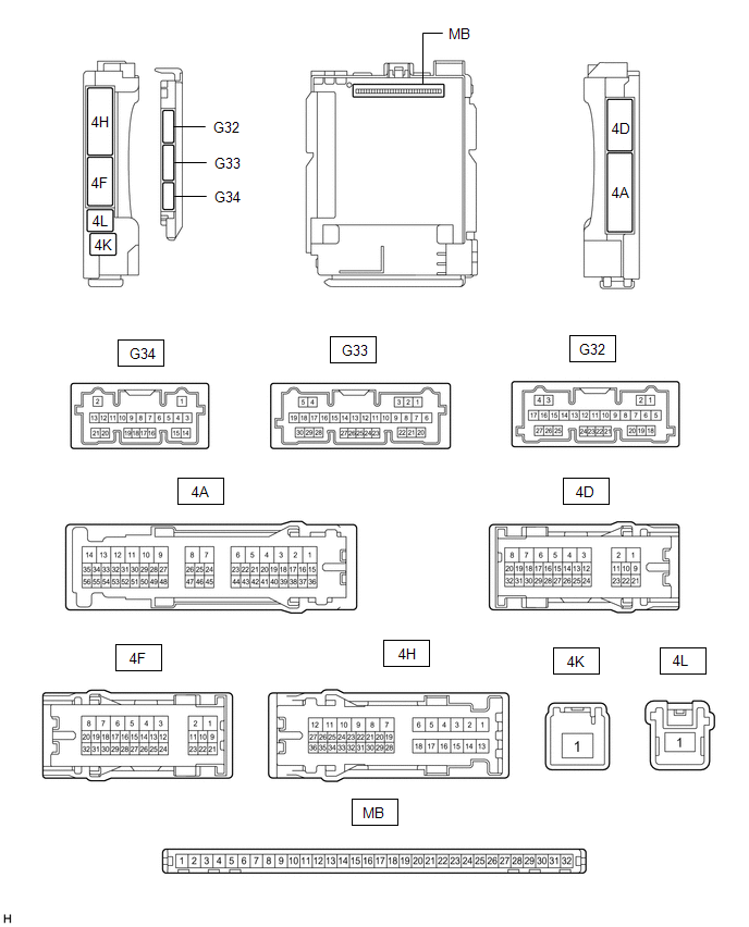
Terminal No. (Symbol) | Wiring Color |
Input/Output | Terminal Description |
Condition | Specified Condition |
Related Data List Item |
|
G33-1 (FLCY) - Body ground |
W- Body ground | Input |
Front door courtesy light switch (for LH) input |
Front door LH open → closed |
Below 1 V → 11 to 14 V |
FL Door Courtesy SW |
|
G33-6 (FRCY) - Body ground |
BE - Body ground | Input |
Front door courtesy light switch (for RH) input |
Front door RH open → closed |
Below 1 V → 11 to 14 V |
FR Door Courtesy SW |
|
4H-24 (LCTY) - Body ground |
G - Body ground | Input |
Rear door courtesy light switch (for LH) input |
Rear door LH open → closed |
Below 1 V → 11 to 14 V |
RL Door Courtesy SW |
|
4A-31 (RCTY) - Body ground |
V - Body ground | Input |
Rear door courtesy light switch (for RH) input |
Rear door RH open → closed |
Below 1 V → 11 to 14 V |
RR Door Courtesy SW |
|
4D-13 (LSFL) - Body ground |
W - Body ground | Input |
Front door LH unlock detection switch input |
Front door LH unlocked → locked |
Below 1 V → 11 to 14 V |
FL Door Lock Pos SW |
|
4D-12 (LSFR) - Body ground |
GR - Body ground | Input |
Front door RH unlock detection switch input |
Front door RH unlocked → locked |
Below 1 V → 11 to 14 V |
FR Door Lock Pos SW |
|
4D-14 (LSWL) - Body ground |
GR - Body ground | Input |
Rear door LH unlock detection switch input |
Rear door LH unlocked → locked |
Below 1 V → 11 to 14 V |
RL-Door Lock Pos SW |
|
G32-20 (LSWR) - Body ground |
L - Body ground | Input |
Rear door RH unlock detection switch input |
Rear door RH unlocked → locked |
Below 1 V → 11 to 14 V |
RR-Door Lock Pos SW |
|
4H-8 (ACT-) - Body ground |
LA-R - Body ground | Output |
Door lock motor unlock drive output |
Door control switch or driver door key cylinder off → on (unlock) |
Below 1 V → 11 to 14 V → Below 1 V |
- |
| 4H-9 (ACT-) - Body ground |
R - Body ground | Output |
Door lock motor unlock drive output |
Door control switch or driver door key cylinder off → on (unlock) |
Below 1 V → 11 to 14 V → Below 1 V |
- |
| 4H-6 (ACT+) - Body ground |
LA-B - Body ground | Output |
Door lock motor lock drive output |
Door control switch or driver door key cylinder off → on (lock) |
Below 1 V → 11 to 14 V → Below 1 V |
- |
| 4H-18 (ACT+) - Body ground |
LA-B - Body ground | Output |
Door lock motor lock drive output |
Door control switch or driver door key cylinder off → on (lock) |
Below 1 V → 11 to 14 V → Below 1 V |
- |
| 4D-4 (ACTD) - Body ground |
LA-L - Body ground | Output |
Door lock motor unlock drive output |
Door control switch or driver door key cylinder off → on (unlock) |
Below 1 V → 11 to 14 V → Below 1 V |
- |
| 4D-16 (L1) - Body ground |
LG - Body ground | Output |
Door control switch assembly input |
Door control switch assembly off → on (lock) |
Pulse generation → Below 1 V |
Door Lock SW-Lock |
|
4A-39 (UL1) - Body ground |
GR - Body ground | Input |
Door control switch assembly input |
Door control switch assembly off → on (unlock) |
Pulse generation → Below 1 V |
Door Lock SW-Unlock |
|
G34-17 (UL3) - Body ground |
BE - Body ground | Input |
Driver door key-linked unlock input |
Driver door key cylinder in neutral position → on (unlock) |
11 to 14 V → Below 1 V |
D Door Key SW-UL |
|
G34-18 (L2) - Body ground |
LG - Body ground | Input |
Driver door key-linked lock input |
Driver door key cylinder in neutral position → on (lock) |
11 to 14 V → Below 1 V |
Door Key SW-Lock |
|
4A-7 (GSW) - Body ground |
B - Body ground | Input |
Airbag sensor signal (collision detection signal) |
Engine switch on (IG) with airbag ECU assembly connector disconnected |
4.3 to 5.5 V | - |