DESCRIPTION
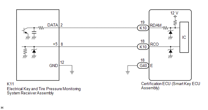
The electrical key and tire pressure monitoring system receiver assembly is used to receive radio waves related to the entry functions of the electrical key transmitter sub-assembly. The certification ECU (smart key ECU assembly) decodes the requested electrical key transmitter sub-assembly operation by identifying a key code based on the radio waves received via the electrical key and tire pressure monitoring system receiver assembly. The electrical key and tire pressure monitoring system receiver assembly receives a signal from the electrical key transmitter sub-assembly and sends signals to the main body ECU (multiplex network body ECU) through the certification ECU (smart key ECU assembly). (ex. If a door lock operation is requested, the certification ECU (smart key ECU assembly) sends a door lock command to the main body ECU (multiplex network body ECU)).
|
DTC No. | Detection Item |
DTC Detection Condition | Trouble Area |
|---|---|---|---|
|
B1242 | Wireless Door Lock Tuner Circuit Malfunction |
|
|
WIRING DIAGRAM
CAUTION / NOTICE / HINT
NOTICE:
Click here 
Click here
) after registration (Click here
) of the transmitter IDs to the electrical key and tire pressure monitoring system receiver assembly.
PROCEDURE
|
1. | CHECK CERTIFICATION ECU (SMART KEY ECU ASSEMBLY) |
(a) Disconnect the K11 electrical key and tire pressure monitoring system receiver assembly connector.
(b) Measure the voltage and resistance and check for pulses according to the value(s) in the table below.
|
*a | Component with harness connected (Certification ECU (Smart Key ECU Assembly)) |
- | - |
Standard Voltage:
|
Tester Connection | Condition |
Specified Condition |
|---|---|---|
|
K10-19 (RDAM) - G40-18 (E) |
Always | 11 to 14 V |
|
K10-18 (RCO) - G40-18 (E) |
Always | Below 1 V → 4.5 to 5.5 V pulse generation at regular intervals |
Standard Resistance:
|
Tester Connection | Condition |
Specified Condition |
|---|---|---|
|
G40-18 (E) - Body ground |
Always | Below 1 Ω |
| OK |  | REPLACE ELECTRICAL KEY AND TIRE PRESSURE MONITORING SYSTEM RECEIVER ASSEMBLY |
|
| 2. |
CHECK HARNESS AND CONNECTOR (ELECTRICAL KEY AND TIRE PRESSURE MONITORING SYSTEM RECEIVER ASSEMBLY - CERTIFICATION ECU (SMART KEY ECU ASSEMBLY)) |
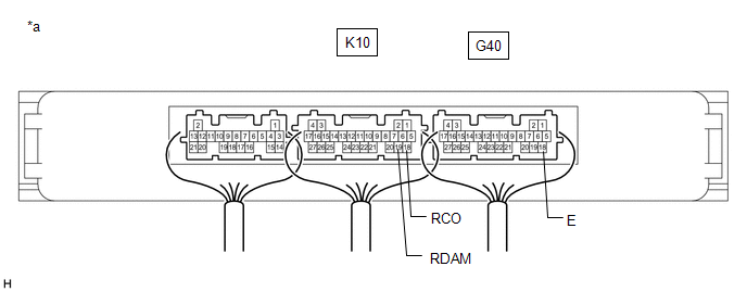
(a) Disconnect the K10 certification ECU (smart key ECU assembly) connector.
(b) Measure the resistance according to the value(s) in the table below.
Standard Resistance:
|
Tester Connection | Condition |
Specified Condition |
|---|---|---|
|
K10-19 (RDAM) - K11-2 (DATA) |
Always | Below 1 Ω |
|
K10-18 (RCO) - K11-8 (+5) |
Always | Below 1 Ω |
|
K11-12 (GND) - Body ground |
Always | Below 1 Ω |
|
K10-19 (RDAM) or K11-2 (DATA) - Other terminals and body ground |
Always | 10 kΩ or higher |
|
K10-18 (RCO) or K11-8 (+5) - Other terminals and body ground |
Always | 10 kΩ or higher |
| OK | | REPLACE CERTIFICATION ECU (SMART KEY ECU ASSEMBLY) |
| NG | | REPAIR OR REPLACE HARNESS OR CONNECTOR |
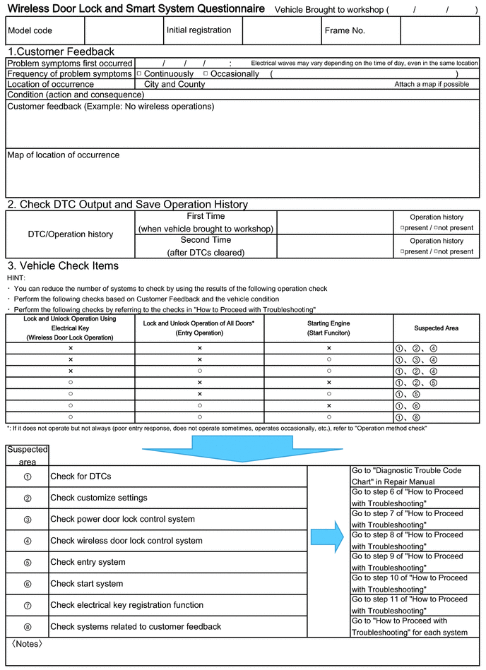
CUSTOMER PROBLEM ANALYSIS CHECK
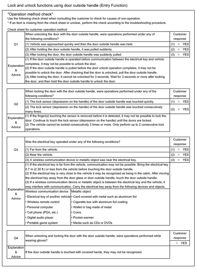
HINT:
Be sure to ask the customer in detail about the following points concerning the vehicle operating conditions, environment and problem, and then check for DTCs.
HINT:
If it is suspected that wave interference is likely, be sure to ask the customer in detail about the following points concerning the vehicle operating conditions, environment and problem.
Click here 
CUSTOMIZE PARAMETERS
CUSTOMIZE WIRELESS DOOR LOCK CONTROL SYSTEM
NOTICE:
HINT:
The following items can be customized.
(a) Customizing with the Techstream
(1) Connect the Techstream to the DLC3.
(2) Turn the engine switch on (IG).
(3) Turn the Techstream on.
(4) Enter the following menus: Customize Setting / Wireless Door Lock.
(5) Select the setting by referring to the table below.
Wireless Door Lock|
Tester Display | Description |
Default | Setting |
ECU |
|---|---|---|---|---|
| Wireless Control |
Function that turns the wireless door lock control system on or off |
ON | 0:OFF,1:ON |
Main body ECU (Multiplex network body ECU) |
|
Hazard Answer Back | Function that flashes the hazard warning lights once when the doors are locked by wireless operation and twice when the doors are unlocked by wireless operation | ON |
0:OFF,1:ON | Main body ECU (Multiplex network body ECU) |
|
Open Door Warning | Function that sounds a buzzer when the lock switch is pressed when any of the doors are ajar |
ON | 0:OFF,1:ON |
Main body ECU (Multiplex network body ECU) |
|
Unlock 2 Operation | Function that unlocks the driver door when the unlock switch on the electrical key transmitter sub-assembly is pressed once, and unlocks all of the doors when pressed twice. If this setting is OFF, pressing the unlock switch once unlocks all of the doors. |
ON | 0:OFF,1:ON |
Main body ECU (Multiplex network body ECU) |
|
Panic Function | Function that operates the theft deterrent system by pressing the panic switch on the electrical key transmitter sub-assembly for 0.8 seconds |
ON | 0:OFF,1:ON |
Main body ECU (Multiplex network body ECU) |
|
Trunk Lid Operation | Function to change the operation method of opening the luggage compartment door using the electrical key transmitter sub-assembly 1tim ON: Push the luggage door open switch once 2tim ON: Push the luggage door open switch twice Long1: Push the luggage door open switch for 0.8 seconds Long2: Push the luggage door open switch for 1.6 seconds Prohibit: Wireless luggage compartment door open function is off |
Long1 | 000:1tim ON,001:2tim ON,010:Long1,011:Long2,111:Prohibit |
Main body ECU (Multiplex network body ECU) |
|
Auto Lock Time | Function that regulates the interval between unlocking and automatic relocking of the doors |
60 s | 00:30 s,01:60 s,10:120 s |
Main body ECU (Multiplex network body ECU) |
|
Wireless Auto Lock | Function that turns the wireless auto lock function on or off |
ON | 0:OFF,1:ON |
Main body ECU (Multiplex network body ECU) |
|
Wireless Buzzer Resp | Function that enables/disables the wireless door lock buzzer response |
ON | 0:OFF,1:ON |
Main body ECU (Multiplex network body ECU) |
|
P/W Wireless Ope Buzz | Function that enables/disables the wireless power window buzzer response |
ON | 0:OFF,1:ON |
Main body ECU (Multiplex network body ECU) |
|
Wireless Buzzer Vol | Function that adjusts the wireless door lock buzzer volume |
Level5 | 0000:Level7,0001:Level6,0010:Level5,0011:Level4,0100:Level3,0101:Level2,0110:Level1,0111:Level0 |
Main body ECU (Multiplex network body ECU) |
|
Wireless Lock Function with Doors Open |
Function that locks the doors automatically if the lock switch on the electrical key transmitter sub-assembly is pressed with any door open and then all of the doors are closed | ON |
0:OFF,1:ON | Main body ECU (Multiplex network body ECU) |
(b) Customizing with the multi-display
(1) Turn the engine switch on (IG).
(2) Enter the following menus: MENU / Setup / Vehicle / Vehicle Customization / Door Lock Settings.
(3) Select the setting by referring to the table below.
|
Display | Description |
Default | Setting |
Relevant ECU |
|---|---|---|---|---|
| Remote 2-Press Unlock |
Function that unlocks the driver door when the unlock switch on the electrical key transmitter sub-assembly is pressed once, and unlocks all of the doors when pressed twice. If this setting is OFF, pressing the unlock switch once unlocks all of the doors |
On | On or Off |
Main body ECU (Multiplex network body ECU) |
|
Wireless Lock When Door Opened |
Function that locks the doors automatically if the lock switch on the electrical key transmitter sub-assembly is pressed with any door open and then all of the doors are closed | On |
On or Off | Main body ECU (Multiplex network body ECU) |
|
Auto Relock Timer | Function that regulates the interval between unlocking and automatic relocking of the doors |
60 sec. | 30 sec, 60 sec or 120 sec |
Main body ECU (Multiplex network body ECU) |
|
Lock/Unlock Feedback-Lights |
Function that flashes the hazard warning lights once when the doors are locked by wireless operation and twice when the doors are unlocked by wireless operation | On |
On or Off | Main body ECU (Multiplex network body ECU) |
|
Lock/Unlock Feedback-Tone |
Function that adjusts the wireless door lock buzzer volume |
5 | Off, 1, 2, 3, 4, 5, 6 or 7 |
Main body ECU (Multiplex network body ECU) |
DATA LIST / ACTIVE TEST
DATA LIST
NOTICE:
In the table below, the values listed under "Normal Condition" are reference values. Do not depend solely on these reference values when deciding whether a part is faulty or not.
HINT:
Using the Techstream to read the Data List allows the values or states of switches, sensors, actuators and other items to be read without removing any parts. This non-intrusive inspection can be very useful because intermittent conditions or signals may be discovered before parts or wiring is disturbed. Reading the Data List information early in troubleshooting is one way to save diagnostic time.
(a) Connect the Techstream to the DLC3.
(b) Turn the engine switch on (IG).
(c) Turn the Techstream on.
(d) Enter the following menus: Body Electrical / Main Body or Smart Key / Data List.
(e) Read the Data List according to the display on the Techstream.
Body Electrical > Main Body > Data List|
Tester Display | Measurement Item |
Range | Normal Condition |
Diagnostic Note |
|---|---|---|---|---|
|
ACC SW | Engine switch on (ACC) signal |
OFF or ON | OFF: Engine switch off ON: Engine switch on (ACC) |
- |
| IG SW |
Engine switch on (IG) signal |
OFF or ON | OFF: Engine switch off or on (ACC) ON: Engine switch on (IG) |
- |
| RR Door Courtesy SW |
Rear door courtesy light switch (for RH) signal |
OFF or ON | OFF: Rear door RH closed ON: Rear door RH open |
- |
| RL Door Courtesy SW |
Rear door courtesy light switch (for LH) signal |
OFF or ON | OFF: Rear door LH closed ON: Rear door LH open |
- |
| FR Door Lock Pos |
Front door RH unlock detection switch signal |
LOCK or UNLOCK | LOCK: Front door RH locked UNLOCK: Front door RH unlocked |
- |
| FR Door Courtesy SW |
Front door courtesy light switch (for RH) signal |
OFF or ON | OFF: Front door RH closed ON: Front door RH open |
- |
| FL Door Lock Pos |
Front door LH unlock detection switch signal |
LOCK or UNLOCK | LOCK: Front door LH locked UNLOCK: Front door LH unlocked |
- |
| FL Door Courtesy SW |
Front door courtesy light switch (for LH) signal |
OFF or ON | OFF: Front door LH closed ON: Front door LH open |
- |
| RR-Door Lock Pos SW |
Rear door RH unlock detection switch signal |
OFF or ON | OFF: Rear door RH locked ON: Rear door RH unlocked |
- |
| RL-Door Lock Pos SW |
Rear door LH unlock detection switch signal |
OFF or ON | OFF: Rear door LH locked ON: Rear door LH unlocked |
- |
| Luggage Courtesy SW |
Luggage compartment door courtesy light switch signal |
OFF or ON | OFF: Luggage compartment door closed ON: Luggage compartment door open |
- |
| Wireless Control |
Wireless door lock control function |
OFF or ON | Customize setting displayed |
- |
| Hazard Answer Back |
Hazard light answer-back of wireless function |
OFF or ON | Customize setting displayed |
- |
| Wireless Auto Lock |
Automatic lock function |
OFF or ON | Customize setting displayed |
- |
| Open Door Warning |
Open door warning | OFF or ON |
Customize setting displayed |
- |
| Unlock 2 Operation |
2 press wireless unlock function |
OFF or ON | Customize setting displayed |
- |
| Panic Function |
Panic function | OFF or ON |
Customize setting displayed |
- |
| Auto Lock Time |
Automatic lock time | 30 s, 60 s or 120 s |
Customize setting displayed |
- |
| Wireless Buzzer Resp |
Buzzer answer-back of wireless function |
OFF or ON | Customize setting displayed |
- |
| P/W Wireless Ope Buzz |
Power window buzzer answer-back of wireless function |
OFF or ON | Customize setting displayed |
- |
| Wireless Buzzer Vol |
Wireless door lock buzzer volume |
Level7, Level6, Level5, Level4, Level3, Level2, Level1 or Level0 |
Customize setting displayed |
- |
| Trunk Lid Operation |
Opening of luggage compartment door using electrical key transmitter sub-assembly |
1 tim ON, 2 tim ON, Long1, Long2 or Prohibit |
Customize setting displayed |
- |
| Wireless Lock Function with Doors Open |
Wireless reservation lock function |
OFF or ON | Customize setting displayed |
- |
|
Tester Display | Measurement Item |
Range | Normal Condition |
Diagnostic Note |
|---|---|---|---|---|
|
# Codes | Number of DTCs |
0 to 255 | Number of stored DTCs |
- |
ACTIVE TEST
HINT:
Using the Techstream to perform Active Tests allows relays, VSVs, actuators and other items to be operated without removing any parts. This non-intrusive functional inspection can be very useful because intermittent operation may be discovered before parts or wiring is disturbed. Performing Active Tests early in troubleshooting is one way to save diagnostic time. Data List information can be displayed while performing Active Tests.
(a) Connect the Techstream to the DLC3.
(b) Turn the engine switch on (IG).
(c) Turn the Techstream on.
(d) Enter the following menus: Body Electrical / Main Body / Active Test.
(e) Perform the Active Test according to the display on the Techstream.
Body Electrical > Main Body > Active Test|
Tester Display | Measurement Item |
Control Range | Diagnostic Note |
|---|---|---|---|
|
Door Lock | Door lock motor |
OFF/Unlock/Lock | - |
|
D-Door Unlock | Driver door lock motor |
OFF/ON | - |
|
Wireless Buzzer | Wireless door lock buzzer |
OFF/ON | - |
DIAGNOSTIC TROUBLE CODE CHART
Wireless Door Lock Control System (for Gasoline Model)|
DTC No. | Detection Item |
Link |
|---|---|---|
| B1242 |
Wireless Door Lock Tuner Circuit Malfunction |
|
DTC CHECK / CLEAR
NOTICE:
CHECK DTC
(a) Connect the Techstream to the DLC3.
(b) Turn the engine switch on (IG).
(c) Turn the Techstream on.
(d) Enter the following menus: Body Electrical / Smart Key / Trouble Codes.
Body Electrical > Smart Key > Trouble Codes(e) Check for DTCs.
Click here 
CLEAR DTC
(a) Connect the Techstream to the DLC3.
(b) Turn the engine switch on (IG).
(c) Turn the Techstream on.
(d) Enter the following menus: Body Electrical / Smart Key / Trouble Codes.
Body Electrical > Smart Key > Clear DTCs(e) Clear the DTCs.
CAUTION / NOTICE / HINT
NOTICE:
Make sure to check the following before proceeding with troubleshooting.
HINT:
PROCEDURE
|
1. | VEHICLE BROUGHT TO WORKSHOP |
(a) Confirm how the vehicle was brought to the workshop.
HINT:
The cause of the malfunction may be narrowed down by confirming whether the vehicle was driven or towed.
| NEXT |  | GO TO SMART KEY SYSTEM (for Start Function) |
DESCRIPTION
In some cases, wireless door lock control functions are normal but the hazard warning light and wireless door lock buzzer answer-back function do not operate. In such cases, hazard warning light and wireless door lock buzzer signal outputs from the main body ECU (multiplex network body ECU) may be malfunctioning.
WIRING DIAGRAM
CAUTION / NOTICE / HINT
NOTICE:
Click here 
Click here
PROCEDURE
|
1. | CHECK CUSTOMIZE SETTING USING TECHSTREAM (Hazard Answer Back, Wireless Buzzer Resp, Wireless Buzzer Vol) |
(a) Connect the Techstream to the DLC3.
(b) Turn the engine switch on (IG).
(c) Turn the Techstream on.
(d) Enter the following menus: Customize Setting / Wireless Door Lock.
(e) Select the setting by referring to the table below.
Wireless Door Lock|
Tester Display | Description |
Default | Setting |
ECU |
|---|---|---|---|---|
| Hazard Answer Back |
Function that flashes the hazard warning lights once when the doors are locked by wireless operation and twice when the doors are unlocked by wireless operation | ON |
0:OFF,1:ON | Main body ECU (Multiplex network body ECU) |
|
Wireless Buzzer Resp | Function that enables/disables the wireless door lock buzzer response |
ON | 0:OFF,1:ON |
Main body ECU (Multiplex network body ECU) |
|
Wireless Buzzer Vol | Function that adjusts the wireless door lock buzzer volume |
Level5 | 0000:Level7,0001:Level6,0010:Level5,0011:Level4,0100:Level3,0101:Level2,0110:Level1,0111:Level0 |
Main body ECU (Multiplex network body ECU) |
|
Result | Proceed to |
|---|---|
|
All settings are ON and other than Level0 |
A |
| A setting is OFF or Level0 |
B |
| B |
 | PERFORM CUSTOMIZE FUNCTION |
|
| 2. |
CHECK WIRELESS DOOR LOCK CONTROL FUNCTIONS |
(a) Check the wireless door lock control function using the electrical key transmitter sub-assembly.
Click here
|
Result | Proceed to |
|---|---|
|
Wireless door lock/unlock operates properly. |
A |
| Wireless door lock/unlock does not operate properly. |
B |
| B |
| GO TO PROBLEM SYMPTOMS TABLE |
|
| 3. |
READ VALUE USING TECHSTREAM (FR Door Lock Pos, FL Door Lock Pos, RR-Door Lock Pos SW, RL-Door Lock Pos SW) |
(a) Connect the Techstream to the DLC3.
(b) Turn the engine switch on (IG).
(c) Turn the Techstream on.
(d) Enter the following menus: Body Electrical / Main Body / Data List.
(e) Read the Data List according to the display on the Techstream.
Body Electrical > Main Body > Data List|
Tester Display | Measurement Item |
Range | Normal Condition |
Diagnostic Note |
|---|---|---|---|---|
|
FR Door Lock Pos | Front door RH unlock detection switch signal |
LOCK or UNLOCK | LOCK: Front door RH locked UNLOCK: Front door RH unlocked |
- |
| FL Door Lock Pos |
Front door LH unlock detection switch signal |
LOCK or UNLOCK | LOCK: Front door LH locked UNLOCK: Front door LH unlocked |
- |
| RR-Door Lock Pos SW |
Rear door RH unlock detection switch signal |
OFF or ON | OFF: Rear door RH locked ON: Rear door RH unlocked |
- |
| RL-Door Lock Pos SW |
Rear door LH unlock detection switch signal |
OFF or ON | OFF: Rear door LH locked ON: Rear door LH unlocked |
- |
|
Tester Display |
|---|
| FR Door Lock Pos |
|
FL Door Lock Pos |
|
RR-Door Lock Pos SW |
|
RL-Door Lock Pos SW |
OK:
The Techstream display changes correctly in response to the lock/unlock operation.
| NG | | GO TO LIGHTING SYSTEM (Proceed to Door Unlock Detection Switch Circuit) |
|
| 4. |
CHECK WIRELESS ANSWER-BACK OPERATION |
(a) Check the wireless answer-back operation using the electrical key transmitter sub-assembly.
Click here
|
Result | Proceed to |
|---|---|
|
Only wireless door lock buzzer answer-back does not occur. |
A |
| Only hazard warning light answer-back does not occur. |
B |
| B |
| GO TO STEP 9 |
|
| 5. |
PERFORM ACTIVE TEST USING TECHSTREAM (Wireless Buzzer) |
(a) Connect the Techstream to the DLC3.
(b) Turn the engine switch on (IG).
(c) Turn the Techstream on.
(d) Enter the following menus: Body Electrical / Main Body / Data List.
(e) Perform the Active Test according to the display on the Techstream.
Body Electrical > Main Body > Active Test|
Tester Display | Measurement Item |
Control Range | Diagnostic Note |
|---|---|---|---|
|
Wireless Buzzer | Wireless door lock buzzer |
OFF/ON | - |
|
Tester Display |
|---|
| Wireless Buzzer |
|
Result | Proceed to |
|---|---|
|
Wireless door lock buzzer does not sound |
A |
| Wireless door lock buzzer sounds |
B |
| B |
| REPLACE MAIN BODY ECU (MULTIPLEX NETWORK BODY ECU) |
|
| 6. |
CHECK MAIN BODY ECU (MULTIPLEX NETWORK BODY ECU) |
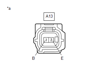
(a) Disconnect the A13 wireless door lock buzzer connector.
(b) Perform the Active Test according to the display on the Techstream.
Body Electrical > Main Body > Active Test|
Tester Display | Measurement Item |
Control Range | Diagnostic Note |
|---|---|---|---|
|
Wireless Buzzer | Wireless door lock buzzer |
OFF/ON | - |
|
Tester Display |
|---|
| Wireless Buzzer |
| (c) Measure the voltage according to the value(s) in the table below. Standard Voltage:
|
|
| OK | | REPLACE WIRELESS DOOR LOCK BUZZER |
|
| 7. |
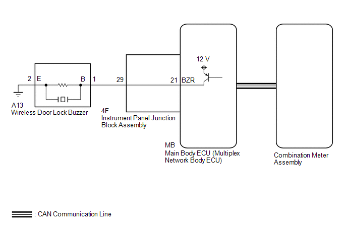
CHECK HARNESS AND CONNECTOR (WIRELESS DOOR LOCK BUZZER - MAIN BODY ECU (MULTIPLEX NETWORK BODY ECU)) |
(a) Remove the main body ECU (multiplex network body ECU) from the instrument panel junction block assembly.
Click here
(b) Reconnect the instrument panel junction block assembly connectors.
(c) Measure the resistance according to the value(s) in the table below.
Standard Resistance:
|
Tester Connection | Condition |
Specified Condition |
|---|---|---|
|
A13-1 (B) - MB-21 (BZR) |
Always | Below 1 Ω |
|
A13-2 (E) - Body ground |
Always | Below 1 Ω |
|
A13-1 (B) or MB-21 (BZR) - Other terminals and body ground |
Always | 10 kΩ or higher |
| OK | | REPLACE MAIN BODY ECU (MULTIPLEX NETWORK BODY ECU) |
|
| 8. |
CHECK HARNESS AND CONNECTOR (WIRELESS DOOR LOCK BUZZER - INSTRUMENT PANEL JUNCTION BLOCK ASSEMBLY) |
(a) Disconnect the 4F instrument panel junction block assembly connector.
(b) Measure the resistance according to the value(s) in the table below.
Standard Resistance:
|
Tester Connection | Condition |
Specified Condition |
|---|---|---|
|
A13-1 (B) - 4F-29 | Always |
Below 1 Ω |
|
A13-1 (B) or 4F-29 - Other terminals and body ground |
Always | 10 kΩ or higher |
| OK | | REPLACE INSTRUMENT PANEL JUNCTION BLOCK ASSEMBLY |
| NG | | REPAIR OR REPLACE HARNESS OR CONNECTOR |
| 9. |
CHECK HAZARD WARNING LIGHTS OPERATION |
(a) Check that the hazard warning lights blink when the hazard warning signal switch is pressed.
OK:
Hazard warning lights blink.
|
Result | Proceed to |
|---|---|
|
OK | A |
|
NG (w/ Cornering Light) |
B |
| NG (w/o Cornering Light) |
C |
| A |
| REPLACE MAIN BODY ECU (MULTIPLEX NETWORK BODY ECU) |
| B |
| GO TO LIGHTING SYSTEM (Proceed to Hazard Warning Switch Circuit) |
| C |
| GO TO LIGHTING SYSTEM (Proceed to Hazard Warning Switch Circuit) |
OPERATION CHECK
NOTICE:
Make sure that the vehicle is in an area that allows the wireless control function to operate.
HINT:
CHECK CUSTOMIZE PARAMETERS
(a) The operation check below is based on the non-customized initial condition of the vehicle.
Click here 
CHECK BASIC FUNCTIONS
(a) Check that the LED of the electrical key transmitter sub-assembly illuminates and turns off 3 times when each switch is pressed and held for 5 seconds.
HINT:
If the transmitter LED illuminates once or twice but not a third time when the switch has been pressed and held for 5 seconds or more, it may have a weak battery.
(b) Check that all of the doors lock when the lock switch is pressed.
(c) Check that the driver door unlocks when the unlock switch is pressed once, and all of the doors unlock when pressed twice within 5 seconds.
(d) Check that the luggage compartment door opens when the luggage open switch is pressed and held for 0.8 seconds or more.
CHECK THE CHATTERING PREVENTION FUNCTION
(a) Press and hold the lock or unlock switch on the electrical key transmitter sub-assembly and check that the corresponding operation occurs only once and is not repeated continuously while the switch is held. Then press the switch repeatedly at 1-second intervals, check that the corresponding operation is carried out.
CHECK THE SWITCH OPERATION FAIL-SAFE FUNCTION
(a) Check that the doors cannot be locked/unlocked by operating a switch on an unregistered electrical key transmitter sub-assembly, but that the doors can be locked/unlocked by operating a switch on the registered electrical key transmitter sub-assembly.
CHECK THE REPEAT FUNCTION
(a) Check that all of the doors attempt to automatically lock 1 second after the lock switch has been pressed while the driver door control knob is being held in the unlock position.
CHECK THE AUTOMATIC LOCKING FUNCTION
(a) Check that the doors lock automatically if none of the doors have been opened or all of the doors have not been locked within approximately 60 seconds of all of the doors being unlocked by pressing the unlock switch.
(b) Check that the automatic locking function does not operate when any door has been opened within approximately 60 seconds of unlocking the doors by pressing the unlock switch.
(c) Check that the automatic locking function does not operate when all of the doors have been locked manually (such as using key linked operation, or by pressing the lock switch) within approximately 60 seconds of unlocking the doors by pressing the unlock switch.
HINT:
When the Wireless Lock Function with Doors Open customize setting is set to ON, this function will be disabled even if the Open Door Warning customize setting is set to ON.
CHECK THE DOOR AJAR WARNING BUZZER FUNCTION
(a) Check that the wireless door lock buzzer sounds for approximately 5 seconds when the lock switch is pressed with any of the doors ajar or open.
HINT:
When the Wireless Lock Function with Doors Open customize setting is set to ON, the door ajar warning buzzer function will be disabled even if the Open Door Warning customize setting is set to ON.
CHECK THE WIRELESS RESERVATION LOCK FUNCTION
(a) Check that the doors are locked by performing a wireless lock operation with any door open.
(b) Check that answer-back (wireless door lock buzzer) function operates when the wireless operation is performed and answer-back (hazard warning light) function operates when the doors are closed.
CHECK THE ANSWER-BACK (HAZARD WARNING LIGHT) FUNCTION
(a) When the lock switch is pressed, check that the hazard warning lights flash once simultaneously with the locking operation of all of the doors.
(b) When the unlock switch is pressed, check that the hazard warning lights flash twice simultaneously with the unlocking operation of all of the doors.
CHECK THE ANSWER-BACK (WIRELESS DOOR LOCK BUZZER) FUNCTION
(a) When the lock switch is pressed, check that the buzzer sounds once simultaneously with the locking operation of all of the doors.
(b) When the unlock switch is pressed once, check that the buzzer sounds twice simultaneously with the unlocking operation of the driver door.
CHECK THE PANIC ALARM CONTROL FUNCTION
Click here
CHECK THE ILLUMINATED ENTRY FUNCTION
Click here
CHECK THE SLIDING ROOF OPEN FUNCTION (w/ Sliding Roof System)
Click here
CHECK THE POWER WINDOW OPERATION FUNCTION
Click here
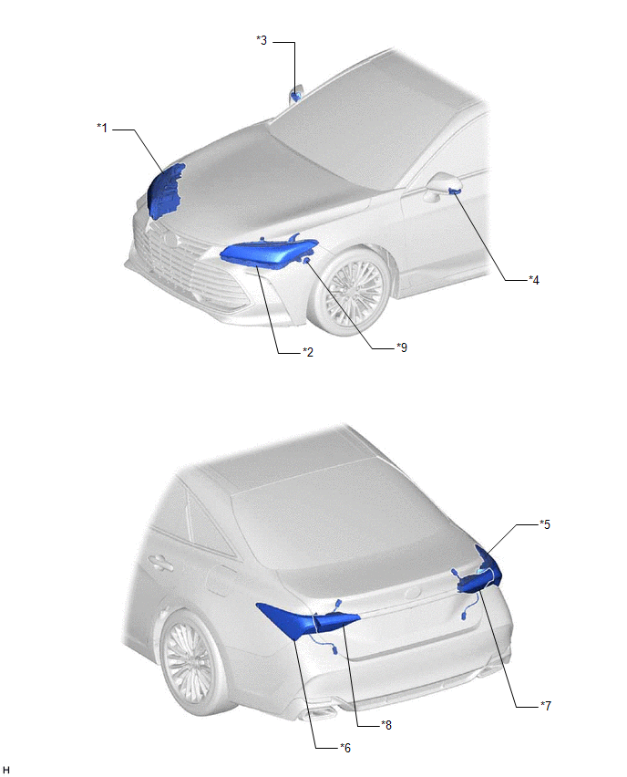
PARTS LOCATION
ILLUSTRATION
|
*1 | HEADLIGHT ASSEMBLY RH - TURN SIGNAL LIGHT | *2 |
HEADLIGHT ASSEMBLY LH - TURN SIGNAL LIGHT |
|
*3 | SIDE TURN SIGNAL LIGHT ASSEMBLY RH |
*4 | SIDE TURN SIGNAL LIGHT ASSEMBLY LH |
|
*5 | REAR COMBINATION LIGHT ASSEMBLY RH - TURN SIGNAL LIGHT | *6 |
REAR COMBINATION LIGHT ASSEMBLY LH - TURN SIGNAL LIGHT |
|
*7 | REAR LIGHT ASSEMBLY RH |
*8 | REAR LIGHT ASSEMBLY LH |
|
*9 | WIRELESS DOOR LOCK BUZZER |
- | - |
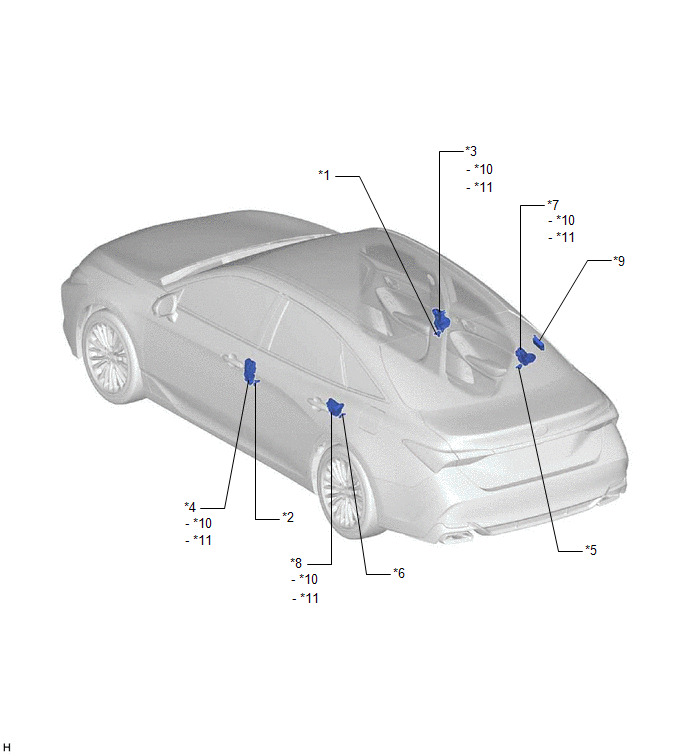
ILLUSTRATION
|
*1 | FRONT DOOR COURTESY LIGHT SWITCH ASSEMBLY (for RH) |
*2 | FRONT DOOR COURTESY LIGHT SWITCH ASSEMBLY (for LH) |
|
*3 | FRONT DOOR LOCK WITH MOTOR ASSEMBLY RH |
*4 | FRONT DOOR LOCK WITH MOTOR ASSEMBLY LH |
|
*5 | REAR DOOR COURTESY LIGHT SWITCH ASSEMBLY (for RH) |
*6 | REAR DOOR COURTESY LIGHT SWITCH ASSEMBLY (for LH) |
|
*7 | REAR DOOR LOCK WITH MOTOR ASSEMBLY RH |
*8 | REAR DOOR LOCK WITH MOTOR ASSEMBLY LH |
|
*9 | ELECTRICAL KEY AND TIRE PRESSURE MONITORING SYSTEM RECEIVER ASSEMBLY |
*10 | DOOR LOCK MOTOR |
|
*11 | DOOR UNLOCK DETECTION SWITCH |
- | - |
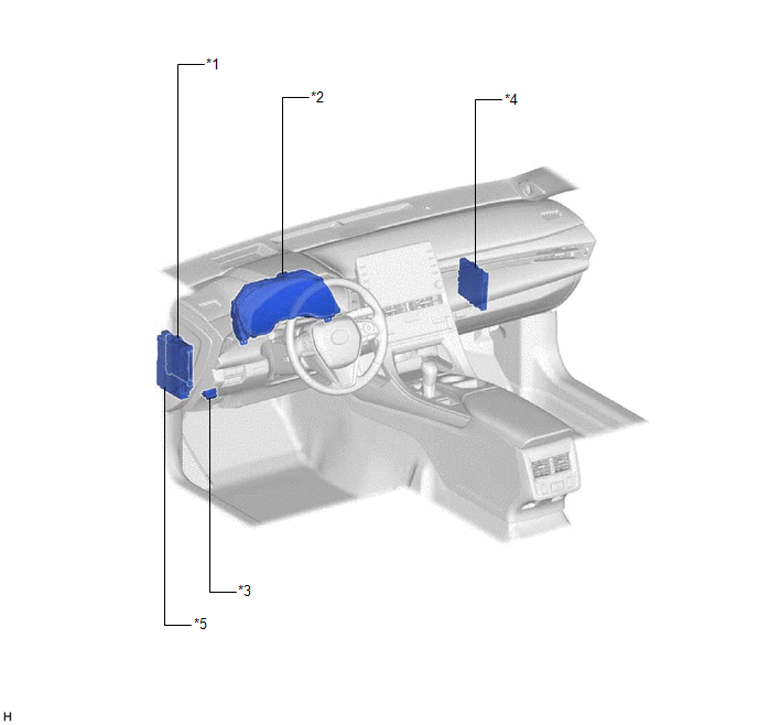
ILLUSTRATION
|
*1 | MAIN BODY ECU (MULTIPLEX NETWORK BODY ECU) |
*2 | COMBINATION METER ASSEMBLY |
|
*3 | DLC3 |
*4 | CERTIFICATION ECU (SMART KEY ECU ASSEMBLY) |
|
*5 | INSTRUMENT PANEL JUNCTION BLOCK ASSEMBLY - AM2 FUSE - ECU-DCC NO. 2 FUSE - ECU-ACC FUSE - ECU-IG1 NO. 4 FUSE |
- | - |
PRECAUTION
PRECAUTION FOR DISCONNECTING CABLE FROM NEGATIVE BATTERY TERMINAL
NOTICE:
When disconnecting the cable from the negative (-) battery terminal, initialize the following systems after the cable is reconnected.
|
System Name | See Procedure |
|---|---|
|
Lane Departure Alert System (w/ Steering Control) |
|
|
Intelligent Clearance Sonar System | |
|
Parking Assist Monitor System | |
|
Panoramic View Monitor System | |
|
Pre-collision System | |
|
Lighting System (for Gasoline Model with Cornering Light) |
PRECAUTIONS WHEN USING TECHSTREAM
(a) When using the Techstream with the engine switch off, connect the Techstream to the DLC3 and turn a courtesy light switch on and off at intervals of 1.5 seconds or less until communication between the Techstream and the vehicle begins. Then select Model Code "KEY REGIST" under manual mode and enter the following menus: Body Electrical / Smart Key(CAN). While using the Techstream, periodically turn a courtesy light switch on and off at intervals of 1.5 seconds or less to maintain communication between the Techstream and the vehicle.
PRECAUTION FOR REGISTRATION
(a) Before replacing any of the following parts, refer to Registration.
Click here 
(b) Electrical key and tire pressure monitoring system receiver assembly
(1) When replacing the electrical key and tire pressure monitoring system receiver assembly, read the transmitter IDs (tire pressure warning system) stored in the old ECU using the Techstream and write them down before removal.
Click here
(2)
If the electrical key and tire pressure monitoring system receiver
assembly has been replaced, it is necessary to perform initialization
(Click here ) after registration (Click here
) of the transmitter IDs to the electrical key and tire pressure monitoring system receiver assembly.
PRECAUTIONS FOR ELECTRICAL KEY TRANSMITTER SUB-ASSEMBLY
Click here
NOTICE WHEN CHECKING FOLLOWING
(a) Wireless door lock/unlock function:
This wireless door lock control function operates only when the following 3 conditions are met:
(1) The engine switch is off.
(2) All of the doors are closed.*
(3) The power door lock control system is operating properly.
HINT:
The unlock function operates even when a door is open.
(b) The size of the wireless door lock control operation area differs depending on the situation.
(1) The size of the operation area differs depending on the user and the way the electrical key transmitter sub-assembly is held.
(2) In certain areas, the wireless door lock control function will only operate partially for the operation area, which will be reduced due to the vehicle body shape and the influence of the surrounding environment.
(3) Since the electrical key transmitter sub-assembly uses weak radio waves, strong radio waves or electrical noise in the frequency used by the electrical key transmitter sub-assembly may reduce the size of the operation area and the remote control may not function.
(4) When the transmitter battery is weak, the size of the operation area is reduced and the remote control may not function.
HINT:
(c) Multi channel function
The wireless door lock control system has a multi channel function. Each time the switch on the electrical key transmitter sub-assembly is pressed, the channel is switched alternately between 2 different frequencies and the signal is sent to the electrical key and tire pressure monitoring system receiver assembly.
PROBLEM SYMPTOMS TABLE
HINT:
|
Symptom | Suspected Area |
Link |
|---|---|---|
|
Wireless control function and entry function do not operate |
Check for DTCs |
|
|
Lighting system (Int) (Front door courtesy switch circuit) | ||
|
Lighting system (Int) (Rear door courtesy switch circuit) | ||
|
Power door lock control system | ||
|
Wave interference | ||
|
Transmitter battery | ||
|
Electrical key transmitter sub-assembly | ||
|
Wire harness or connector | ||
|
Check connector connection condition | ||
|
Electrical key and tire pressure monitoring system receiver assembly | ||
|
Certification ECU (Smart key ECU assembly) | ||
|
Main body ECU (Multiplex network body ECU) | ||
|
B code registration failed | ||
|
Wireless control function does not operate but entry function operates |
Electrical key transmitter sub-assembly |
- |
|
Only answer-back function does not operate properly |
Check customize setting |
|
|
Perform operation check | ||
|
Lighting system (Int) (Door unlock detection switch circuit) | ||
|
Main body ECU (Multiplex network body ECU) | ||
|
Wireless door lock buzzer | ||
|
Instrument panel junction block assembly | ||
|
Wire harness or connector | ||
|
Lighting system (Ext) (Hazard warning switch circuit) | ||
|
Only automatic lock function does not operate properly |
Perform operation check |
|
|
Lighting system (Int) (Front door courtesy switch circuit) |
| |
|
Lighting system (Int) (Rear door courtesy switch circuit) |
| |
|
Main body ECU (Multiplex network body ECU) |
- | |
|
Only illuminated entry function does not operate |
Perform operation check |
|
|
Lighting system (Int) |
| |
|
Main body ECU (Multiplex network body ECU) |
- | |
| Only door ajar warning buzzer function does not operate |
Wireless door lock buzzer |
|
|
Only panic alarm function does not operate |
Perform operation check |
|
|
Lighting system (Int) (Interior lights) |
| |
|
Lighting system (Ext) (Headlights, taillights, hazard warning lights)*1 |
| |
|
Lighting system (Ext) (Headlights, taillights, hazard warning lights)*2 |
| |
|
Theft deterrent system (Vehicle horns, Security horn) |
| |
|
Main body ECU (Multiplex network body ECU) |
- |
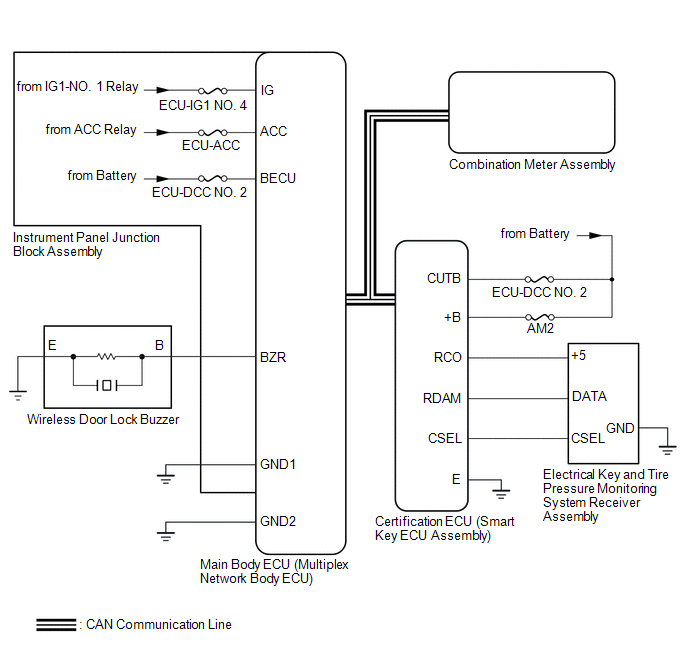
SYSTEM DIAGRAM
WIRELESS DOOR LOCK CONTROL SYSTEM
POWER DOOR LOCK CONTROL SYSTEM
Click here 
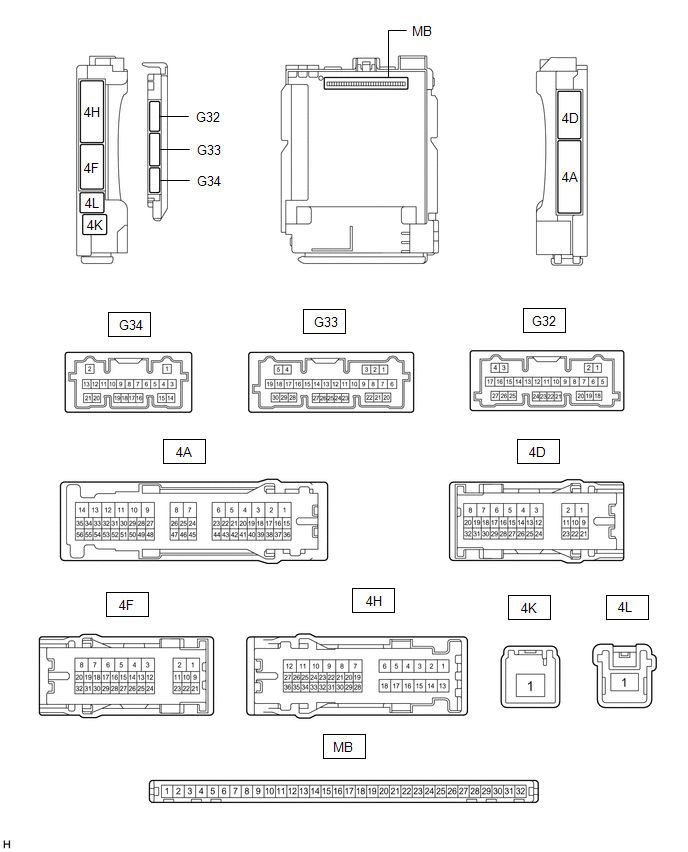
TERMINALS OF ECU
CHECK INSTRUMENT PANEL JUNCTION BLOCK ASSEMBLY AND MAIN BODY ECU (MULTIPLEX NETWORK BODY ECU)
(a) Remove the main body ECU (multiplex network body ECU) from the instrument panel junction block assembly.
Click here 
(b) Measure the resistance according to the value(s) in the table below.
HINT:
Measure the values on the wire harness side with the connectors connected.
|
Terminal No. (Symbol) | Wiring Color |
Input/Output | Terminal Description |
Condition | Specified Condition |
Related Data List Item |
|---|---|---|---|---|---|---|
|
G32-19 (GND2) - Body ground |
W-B - Body ground | - |
Ground | Always |
Below 1 Ω | - |
(c) Reconnect the instrument panel junction block assembly connectors.
(d) Measure the voltage and resistance according to the value(s) in the table below.
|
Terminal No. (Symbol) | Wiring Color |
Input/Output | Terminal Description |
Condition | Specified Condition |
Related Data List Item |
|---|---|---|---|---|---|---|
|
MB-11 (GND1) - Body ground |
- | - |
Ground | Always |
Below 1 Ω | - |
|
MB-30 (ACC) - Body ground |
- | Input |
ACC power supply | Engine switch on (ACC) |
11 to 14 V |
ACC SW |
| Engine switch off |
Below 1 V | |||||
|
MB-31 (BECU) - Body ground |
- | Input |
Battery power supply |
Always | 11 to 14 V |
- |
|
MB-32 (IG) - Body ground |
- | Input |
IG power supply | Engine switch on (IG) |
11 to 14 V |
IG SW |
| Engine switch off |
Below 1 V |
(e) Install the main body ECU (multiplex network body ECU) to the instrument panel junction block assembly.
Click here
(f) Measure the voltage and check for pulses according to the value(s) in the table below.
|
Terminal No. (Symbol) | Wiring Color |
Input/Output | Terminal Description |
Condition | Specified Condition |
Related Data List Item |
|---|---|---|---|---|---|---|
|
4F-29 (BZR) - Body ground |
L - Body ground |
Output | Wireless door lock buzzer output |
Active Test Wireless Buzzer is OFF |
Below 1 V |
- |
| Active Test Wireless Buzzer is ON |
Pulse generation (frequency: 2 kHz, high voltage: 11 to 14 V, low voltage: below 1 V) |
CHECK CERTIFICATION ECU (SMART KEY ECU ASSEMBLY)

(a) Disconnect the G40 certification ECU (smart key ECU assembly) connector.
(b) Measure the voltage and resistance according to the value(s) in the table below.
|
Terminal No. (Symbol) | Wiring Color |
Input/Output | Terminal Description |
Condition | Specified Condition |
Related Data List Item |
|---|---|---|---|---|---|---|
|
G40-4 (+B) - Body ground |
W - Body ground | Input |
Battery power supply |
Always | 11 to 14 V |
- |
| G40-18 (E) - Body ground |
W-B - Body ground | - |
Ground | Always |
Below 1 Ω | - |
(c) Reconnect the G40 certification ECU (smart key ECU assembly) connector.
(d) Check for pulses according to the value(s) in the table below.
|
Terminal No. (Symbol) | Wiring Color |
Input/Output | Terminal Description |
Condition | Specified Condition |
Related Data List Item |
|---|---|---|---|---|---|---|
|
K10-18 (RCO) - G40-18 (E) |
B - W-B | Output |
Output to electrical key and tire pressure monitoring system receiver assembly (Power supply for electrical key and tire pressure monitoring system receiver assembly. Certification ECU (smart key ECU assembly) outputs 5 V when receiver starts operating.) | Procedure:
| Plus generation (See waveform 1) |
- |
| K10-19 (RDAM) - G40-18 (E) |
G - W-B | Input |
Electrical key and tire pressure monitoring system receiver assembly communication circuit | Procedure:
| Plus generation (See waveform 2) |
- |
| K10-20 (CSEL) - G40-18 (E) |
BE - W-B | Output |
Communication channel switching circuit | Procedure:
| No pulse generation → Pulse generation |
- |
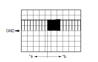
(e) Using an oscilloscope, check waveform 1.
HINT:
The oscilloscope waveform shown in the illustration is an example for reference only. Noise, chattering, etc. are not shown.
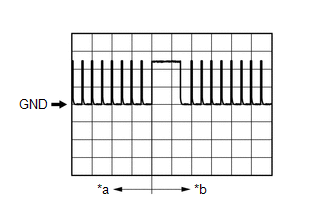
|
*a | Before lock or unlock switch of electrical key transmitter sub-assembly pressed |
|
*b | After lock or unlock switch of electrical key transmitter sub-assembly pressed |
|
Item | Content |
|---|---|
|
Tester connection | K10-18 (RCO) - G40-18 (E) |
|
Tool setting | 2 V/DIV., 500 ms/DIV. |
|
Condition | Procedure:
|
(f) Using an oscilloscope, check waveform 2.
HINT:
The oscilloscope waveform shown in the illustration is an example for reference only. Noise, chattering, etc. are not shown.
|
*a | Before lock or unlock switch of electrical key transmitter sub-assembly pressed |
|
*b | After lock or unlock switch of electrical key transmitter sub-assembly pressed |
|
Item | Content |
|---|---|
|
Tester connection | K10-19 (RDAM) - G40-18 (E) |
|
Tool setting | 5 V/DIV., 500 ms/DIV. |
|
Condition | Procedure:
|
Toyota Avalon (XX50) 2019-2022 Owners Manual > Multi-information
display: Suggestion function
Displays suggestions to the driver in the following situations. To select a response to a displayed suggestion, use the meter control switches. The suggestion function can be turned on/off. ■ Suggestion to turn off the headlights If the headlights are left on for a certain amount of time after the ...