Toyota Avalon (XX50) 2019-2022 Service & Repair Manual: Room Temperature Sensor Circuit (B1411)

DESCRIPTION

The cooler (room temp. sensor) thermistor is installed in the instrument panel to detect the cabin temperature, which is used to control the air conditioning system. The resistance of the cooler (room temp. sensor) thermistor changes in accordance with the cabin temperature. As the temperature decreases, the resistance increases. As the temperature increases, the resistance decreases.

The air conditioning amplifier assembly applies voltage (5 V) to the cooler (room temp. sensor) thermistor and reads voltage changes due to changes in the resistance of the cooler (room temp. sensor) thermistor.

DTC No.

Detection Item

DTC Detection Condition

Trouble Area

Memory

B1411

Room Temperature Sensor Circuit

Open or short in room temperature sensor circuit

  • Cooler (room temp. sensor) thermistor
  • Harness or connector
  • Air conditioning amplifier assembly

Memorized

(4 sec. or more)*

  • *: The air conditioning amplifier assembly stores this DTC if the malfunction has occurred for the period of time indicated in the brackets.

HINT:

If the cabin temperature is approximately -18.6°C (-1.48°F) or lower, DTC B1411 may be stored even though the system is normal.

WIRING DIAGRAM
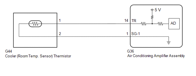
PROCEDURE

1.

READ VALUE USING TECHSTREAM

(a) Connect the Techstream to the DLC3.

(b) Turn the engine switch on (IG).

(c) Turn the Techstream on.

(d) Enter the following menus: Body Electrical / Air Conditioner / Data List.

(e) Read the Data List according to the display on the Techstream.

Body Electrical > Air Conditioner > Data List

Tester Display

Measurement Item

Range

Normal Condition

Diagnostic Note

Room Temperature Sensor

Cooler (room temp. sensor) thermistor

Min.: -6.50°C (20.30°F)

Max.: 57.25°C (135.05°F)

Actual cabin temperature displayed

Cooler (room temp. sensor) thermistor circuit malfunction

  • When open circuit: -6.50°C (20.30°F)
  • When short circuit: 57.25°C (135.05°F)
Body Electrical > Air Conditioner > Data List

Tester Display

Room Temperature Sensor

OK:

The display is as specified in the normal condition column.

OK

REPLACE AIR CONDITIONING AMPLIFIER ASSEMBLY

NG

2.

INSPECT COOLER (ROOM TEMP. SENSOR) THERMISTOR

(a) Remove the cooler (room temp. sensor) thermistor.

Click here

(b) Inspect the cooler (room temp. sensor) thermistor.

Click here

NG

REPLACE COOLER (ROOM TEMP. SENSOR) THERMISTOR

OK

3.

CHECK HARNESS AND CONNECTOR (COOLER (ROOM TEMP. SENSOR) THERMISTOR - AIR CONDITIONING AMPLIFIER ASSEMBLY)

(a) Disconnect the G36 air conditioning amplifier assembly connector.

(b) Measure the resistance according to the value(s) in the table below.

Standard Resistance:

Tester Connection

Condition

Specified Condition

G44-1 - G36-14 (TR)

Always

Below 1 Ω

G44-2 - G36-1 (SG-1)

Always

Below 1 Ω

G44-1 or G36-14 (TR) - Other terminals and body ground

Always

10 kΩ or higher

G44-2 or G36-1 (SG-1) - Other terminals and body ground

Always

10 kΩ or higher

OK

REPLACE AIR CONDITIONING AMPLIFIER ASSEMBLY

NG

REPAIR OR REPLACE HARNESS OR CONNECTOR

    Refrigerant Overabundance Filling Malfunction (B14BD)

    Ambient Temperature Sensor Circuit (B1412)

    See More:

    Toyota Avalon (XX50) 2019-2022 Service & Repair Manual > Smart Key System(for Entry Function, Gasoline Model): Driver Side Door Entry Unlock Function does not Operate
    DESCRIPTION If the entry unlock function does not operate for the driver door only, but the entry lock function operates, the request code is being transmitted properly from the driver door. In this case, there may be a problem related to the unlock sensor (connection between the certification ECU ( ...

    Toyota Avalon (XX50) 2019-2022 Owners Manual

    Toyota Avalon (XX50) 2019-2022 Service & Repair Manual

    © 2024 Copyright www.tavalon.net
    0.0172