DESCRIPTION If the cooling effect of the air conditioning system is weak, the following factors may be the cause. |
Symptom | Factor |
- Cooling effectiveness is poor
- Cooling response is slow
|
- ECO mode control of air conditioning system is enabled
- Cooler compressor assembly malfunction
- Refrigerant volume (high)
- Refrigerant volume (low)
- Clogged cooler condenser assembly fins
- Cooling fan system malfunction
- Mechanical locking of damper and damper link
- Automatic light control sensor malfunction
- High inlet air temperature
- Harness or connector
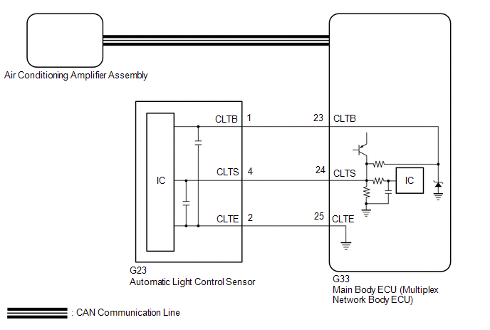
| WIRING DIAGRAM
 PROCEDURE
| 1. |
CHECK ECO MODE SETTING | (a) Check if the ECO mode indicator is off.
OK: The ECO mode indicator is off.
| OK |
 | GO TO STEP 3 |
|
NG |
 | |
| 2. |
CHECK ECO MODE CONTROL OPERATION | (a)
Operate the ECO switch assembly (electric parking brake switch
assembly) and check that the ECO mode indicator turns off and the blower
speed reduction is canceled.
HINT:
- When ECO mode control is operating, the air conditioning amplifier
assembly controls the air conditioning system to enhance fuel
efficiency. Therefore, explain to the customer that, when ECO mode
control is operating, the blower speed will be reduced.
|
Control |
Outline |
|
Blower Control |
When
the air conditioning system is in AUTO mode, the blower speed will be
reduced to a certain speed. Additionally, if warm-up control is
operating, the blower speed will be further reduced. |
|
Air Inlet Control |
If the ambient temperature is a certain value or more, the air inlet mode will be changed to recirculation mode.
|
- In some situations, ECO mode control may not operate even though it is enabled.
|
Result | Proceed to | |
ECO mode indicator turns off and blower speed reduction is canceled |
A | | ECO mode indicator turns off, but the blower speed reduction is not canceled |
B | | ECO mode indicator does not turn off |
| B |
| GO TO ECO Switch Circuit |
|
A | |
| |
| 3. |
PERFORM REFRIGERANT SHORTAGE CHECK | (a) Connect the Techstream to the DLC3.
(b) Turn the engine switch on (IG). (c) Turn the Techstream on.
(d) Enter the following menus: Body Electrical / Air Conditioner / Utility / Refrigerant Gas Volume Check. Body Electrical > Air Conditioner > Utility
|
Tester Display | | Refrigerant Gas Volume Check |
(e)
Check that the following conditions are met and perform the refrigerant
shortage check according to the display on the Techstream. Measurement Condition: |
Item | Condition | |
A/C switch | On | |
Ambient temperature* |
0 to 49°C (32 to 120°F) | |
Blower speed | HI |
*: If the ambient temperature is not within the range shown, do not perform this check. |
Result | Amount of Refrigerant | |
Refrigerant correct | Correct | |
Refrigerant shortage |
Insufficient | OK: "Refrigerant correct" is displayed on the Techstream.
| NG |
| REPAIR REFRIGERANT LEAK |
|
OK | |
| |
| 4. |
PERFORM ACTIVE TEST USING TECHSTREAM | (a) Connect the Techstream to the DLC3.
(b) Turn the engine switch on (IG). (c) Turn the Techstream on.
(d) Enter the following menus: Body Electrical / Air Conditioner / Active Test.
(e) Perform the Active Test according to the display on the Techstream. Body Electrical > Air Conditioner > Active Test
|
Tester Display | Measurement Item |
Control Range | Diagnostic Note | |
Air Mix Servo Targ Pulse(D) |
No. 1 air conditioning radiator damper servo sub-assembly (driver side air mix) pulse |
Min.: 128 Max.: 383 |
Operates between 165 and 257 pulses | |
Air Mix Servo Targ Pulse(P) |
No. 1 air conditioning radiator damper servo sub-assembly (front passenger side air mix) pulse |
Min.: 128 Max.: 383 |
Operates between 255 and 347 pulses | Body Electrical > Air Conditioner > Active Test
|
Tester Display | | Air Mix Servo Targ Pulse(D) | Body Electrical > Air Conditioner > Active Test
|
Tester Display | | Air Mix Servo Targ Pulse(P) |
OK: Each damper servo motor operates.
| NG |
| GO TO DTC TROUBLESHOOTING PROCEDURE FOR MALFUNCTIONING DAMPER SERVO MOTOR |
|
OK | |
| |
| 5. |
CHECK HARNESS AND CONNECTOR (AUTOMATIC LIGHT CONTROL SENSOR - MAIN BODY ECU (MULTIPLEX NETWORK BODY ECU)) |
(a) Disconnect the G23 automatic light control sensor connector. (b) Disconnect the G33 main body ECU (multiplex network body ECU) connector.
(c) Measure the resistance according to the value(s) in the table below.
Standard Resistance: |
Tester Connection | Condition |
Specified Condition | |
G23-1 (CLTB) - G33-23 (CLTB) |
Always | Below 1 Ω | |
G23-2 (CLTE) - G33-25 (CLTE) |
Always | Below 1 Ω | |
G23-4 (CLTS) - G33-24 (CLTS) |
Always | Below 1 Ω | |
G23-1 (CLTB) or G33-23 (CLTB) - Other terminals and body ground |
Always | 10 kΩ or higher | |
G23-2 (CLTE) or G33-25 (CLTE) - Other terminals and body ground |
Always | 10 kΩ or higher | |
G23-4 (CLTS) or G33-24 (CLTS) - Other terminals and body ground |
Always | 10 kΩ or higher |
| NG |
| REPAIR OR REPLACE HARNESS OR CONNECTOR |
|
OK | |
| |
| 6. |
INSPECT AUTOMATIC LIGHT CONTROL SENSOR |
(a) Remove the automatic light control sensor. Click here
 (b) Inspect the automatic light control sensor.
Click here
| OK |
| INSPECT REFRIGERANT PRESSURE WITH MANIFOLD GAUGE SET |
| NG |
| REPLACE AUTOMATIC LIGHT CONTROL SENSOR | | 

