DESCRIPTION
If none of the switch indicators on the air conditioning control panel (radio and display receiver assembly) illuminate, the following factors may be the cause.
|
Symptom | Factor |
|---|---|
|
A/C switch indicator does not illuminate |
|
PROCEDURE
| 1. |
CHECK MALFUNCTION STATUS |
(a) Check the malfunction status of switch indicators on the air conditioning control panel (radio and display receiver assembly).
| Result | Proceed to |
|---|---|
|
Indicators are not always illuminated |
A |
| Indicators are not illuminated only immediately after starting the engine |
B |
| B |
 | GO TO INITIALIZATION |
|
| 2. |
READ VALUE USING TECHSTREAM |
(a) Connect the Techstream to the DLC3.
(b) Turn the engine switch on (IG).
(c) Turn the Techstream on.
(d) Enter the following menus: Body Electrical / Air Conditioner / Data List.
(e) Read the Data List according to the display on the Techstream.
Body Electrical > Air Conditioner > Data List|
Tester Display | Measurement Item |
Range | Normal Condition |
Diagnostic Note |
|---|---|---|---|---|
|
Ambient Temp Sensor | Thermistor assembly |
Min.: -23.30°C (-9.94°F) Max.: 65.95°C (150.71°F) |
Actual ambient temperature displayed |
Thermistor assembly circuit malfunction
|
|
Tester Display |
|---|
| Ambient Temp Sensor |
OK:
The value displayed is 0°C (32°F) or higher.
| OK | | INSPECT REFRIGERANT PRESSURE WITH MANIFOLD GAUGE SET |
| NG | | GO TO OTHER DIAGNOSIS PROCEDURE (Ambient Temperature Display System) |
DESCRIPTION
When the engine is running, If refrigerant pressure does not decrease when the A/C switch is turned off, the following factors may be the cause.
|
Symptom | Factor |
|---|---|
|
|
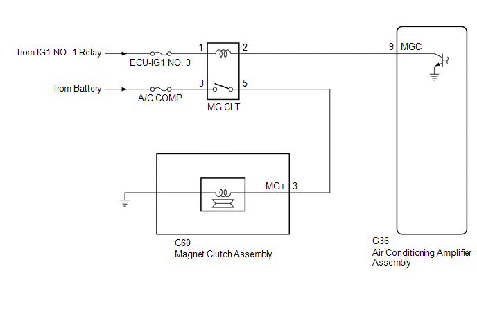
WIRING DIAGRAM
CAUTION / NOTICE / HINT
NOTICE:
Inspect the fuses for circuits related to this system before performing the following procedure.
PROCEDURE
| 1. |
INSPECT MG CLT RELAY |
(a) Inspect the MG CLT relay.
Click here 
| NG |  | REPLACE MG CLT RELAY |
|
| 2. |
CHECK HARNESS AND CONNECTOR (MG CLT RELAY - POWER SOURCE) |
(a) Measure the voltage according to the value(s) in the table below.
Standard Voltage:
|
Tester Connection | Condition |
Specified Condition |
|---|---|---|
|
3 (MG CLT relay) - Body ground |
Always | 11 to 14 V |
|
1 (MG CLT relay) - Body ground |
Engine switch off | Below 1 V |
|
1 (MG CLT relay) - Body ground |
Engine switch on (IG) |
11 to 14 V |
| NG | | REPAIR OR REPLACE HARNESS OR CONNECTOR |
|
| 3. |
CHECK HARNESS AND CONNECTOR (MG CLT RELAY - AIR CONDITIONING AMPLIFIER ASSEMBLY) |
(a) Disconnect the G36 air conditioning amplifier assembly connector.
(b) Measure the resistance according to the value(s) in the table below.
Standard Resistance:
|
Tester Connection | Condition |
Specified Condition |
|---|---|---|
|
2 (MG CLT relay) - G36-9 (MGC) |
Always | Below 1 Ω |
|
2 (MG CLT relay) or G36-9 (MGC) - Other terminals and body ground |
Always | 10 kΩ or higher |
| NG | | REPAIR OR REPLACE HARNESS OR CONNECTOR |
|
| 4. |
CHECK HARNESS AND CONNECTOR (MG CLT RELAY - MAGNET CLUTCH ASSEMBLY AND BODY GROUND) |
(a) Disconnect the C60 magnet clutch assembly connector.
(b) Measure the resistance according to the value(s) in the table below.
Standard Resistance:
|
Tester Connection | Condition |
Specified Condition |
|---|---|---|
|
5 (MG CLT relay) - C60-3 (MG+) |
Always | Below 1 Ω |
|
5 (MG CLT relay) or C60-3 (MG+) - Other terminals and body ground |
Always | 10 kΩ or higher |
| NG | | REPAIR OR REPLACE HARNESS OR CONNECTOR |
|
| 5. |
CHECK HARNESS AND CONNECTOR (MAGNET CLUTCH ASSEMBLY - BODY GROUND) |
(a) Install the MG CLT relay.
(b) Connect the C60 compressor assembly with magnetic clutch connector.
(c) Measure the voltage according to the value(s) in the table below.
Standard Voltage:
|
Tester Connection | Condition |
Specified Condition |
|---|---|---|
|
C60-3 (MG+) - Body ground |
Engine running (A/C switch: Off) |
Below 1 V |
| OK | | REPLACE MAGNET CLUTCH ASSEMBLY |
| NG | | REPAIR OR REPLACE HARNESS OR CONNECTOR |
DESCRIPTION
If the air outlet mode does not change even though the air outlet display changes, the following factors may be the cause.
|
Symptom | Factor |
|---|---|
|
Air outlet mode cannot be changed
|
|
PROCEDURE
| 1. |
CHECK AIR OUTLET SERVO MOTOR |
(a) Confirm for which seat the air outlet mode cannot be changed.
|
Result | Proceed to |
|---|---|
|
The air outlet mode for the driver seat cannot be changed |
A |
| The air outlet mode for the front passenger seat cannot be changed | |
|
The air outlet mode for the rear seats cannot be changed |
B |
| B |
 | GO TO STEP 4 |
|
| 2. |
CHECK NO. 1 AIR CONDITIONING RADIATOR DAMPER SERVO SUB-ASSEMBLY |
(a) Check that the No. 1 air conditioning radiator damper servo sub-assembly is installed correctly.
OK:
The No. 1 air conditioning radiator damper servo sub-assembly is installed correctly.
| NG | | INSTALL NO. 1 AIR CONDITIONING RADIATOR DAMPER SERVO SUB-ASSEMBLY |
|
| 3. |
CHECK FOR DTC |
(a) Check for DTCs.
Body Electrical > Air Conditioner > Trouble Codes|
Result | Proceed to |
|---|---|
|
B1443 is not output | A |
|
B1443 is output | B |
| A |
| REPLACE AIR CONDITIONING RADIATOR ASSEMBLY |
| B |
| GO TO DTC B1443 |
| 4. |
CHECK NO. 2 AIR CONDITIONING RADIATOR DAMPER SERVO SUB-ASSEMBLY |
(a) Check that the No. 2 air conditioning radiator damper servo sub-assembly is installed correctly.
OK:
The No. 2 air conditioning radiator damper servo sub-assembly is installed correctly.
| NG | | INSTALL NO. 2 AIR CONDITIONING RADIATOR DAMPER SERVO SUB-ASSEMBLY |
|
| 5. |
CHECK FOR DTC |
(a) Check for DTCs.
Body Electrical > Air Conditioner > Trouble Codes|
Result | Proceed to |
|---|---|
|
B1449 is not output | A |
|
B1449 is output | B |
| A |
| REPLACE AIR CONDITIONING RADIATOR ASSEMBLY |
| B |
| GO TO DTC B1449 |
DESCRIPTION
If the temperature of the air that blows from the left and right front registers differs, even though the same temperature is set for both sides, the following factors may be the cause.
|
Symptom | Factor |
|---|---|
|
Temperature of outlet air is cooler on left or right side
|
|
| Temperature of outlet air is warmer on left or right side
|
|
WIRING DIAGRAM

CAUTION / NOTICE / HINT
NOTICE:
w/ Cornering Light: Click here 
w/o Cornering Light: Click here
Click here
PROCEDURE
|
1. | CHECK WHEN MALFUNCTION OCCURS |
| Result |
Proceed to |
|---|---|
| When using cooling function |
A |
| When using heater function |
B |
| B |
 | GO TO STEP 6 |
|
| 2. |
PERFORM REFRIGERANT SHORTAGE CHECK |
(a) Connect the Techstream to the DLC3.
(b) Turn the engine switch on (IG).
(c) Turn the Techstream on.
(d) Enter the following menus: Body Electrical / Air Conditioner / Utility / Refrigerant Gas Volume Check.
Body Electrical > Air Conditioner > Utility|
Tester Display |
|---|
| Refrigerant Gas Volume Check |
(e) Check that the following conditions are met and perform the refrigerant shortage check according to the display on the Techstream.
Measurement Condition:|
Item | Condition |
|---|---|
|
A/C switch | On |
|
Ambient temperature* |
0 to 49°C (32 to 120°F) |
|
Blower speed | HI |
*: If the ambient temperature is not within the range shown, do not perform this check.
|
Result | Amount of Refrigerant |
|---|---|
|
Refrigerant correct | Correct |
|
Refrigerant shortage |
Insufficient |
OK:
"Refrigerant correct" is displayed on the Techstream.
| NG | | CHARGE SYSTEM WITH REFRIGERANT |
|
| 3. |
PERFORM ACTIVE TEST USING TECHSTREAM |
(a) Connect the Techstream to the DLC3.
(b) Turn the engine switch on (IG).
(c) Turn the Techstream on.
(d) Enter the following menus: Body Electrical / Air Conditioner / Active Test.
(e) Perform the Active Test according to the display on the Techstream.
Body Electrical > Air Conditioner > Active Test|
Tester Display | Measurement Item |
Control Range | Diagnostic Note |
|---|---|---|---|
|
Air Mix Servo Targ Pulse(D) |
No. 1 air conditioning radiator damper servo sub-assembly (driver side air mix) pulse |
Min.: 128 Max.: 383 |
Operates between 165 and 257 pulses |
|
Air Mix Servo Targ Pulse(P) |
No. 1 air conditioning radiator damper servo sub-assembly (front passenger side air mix) pulse |
Min.: 128 Max.: 383 |
Operates between 255 and 347 pulses |
|
Tester Display |
|---|
| Air Mix Servo Targ Pulse(D) |
|
Tester Display |
|---|
| Air Mix Servo Targ Pulse(P) |
OK:
Each damper servo motor operates.
| NG | | GO TO DTC TROUBLESHOOTING PROCEDURE FOR MALFUNCTIONING DAMPER SERVO MOTOR |
|
| 4. |
CHECK HARNESS AND CONNECTOR (AUTOMATIC LIGHT CONTROL SENSOR - MAIN BODY ECU (MULTIPLEX NETWORK BODY ECU)) |
(a) Disconnect the G23 automatic light control sensor connector.
(b) Disconnect the G33 main body ECU (multiplex network body ECU) connector.
(c) Measure the resistance according to the value(s) in the table below.
Standard Resistance:
|
Tester Connection | Condition |
Specified Condition |
|---|---|---|
|
G23-1 (CLTB) - G33-23 (CLTB) |
Always | Below 1 Ω |
|
G23-2 (CLTE) - G33-25 (CLTE) |
Always | Below 1 Ω |
|
G23-4 (CLTS) - G33-24 (CLTS) |
Always | Below 1 Ω |
|
G23-1 (CLTB) or G33-23 (CLTB) - Other terminals and body ground |
Always | 10 kΩ or higher |
|
G23-2 (CLTE) or G33-25 (CLTE) - Other terminals and body ground |
Always | 10 kΩ or higher |
|
G23-4 (CLTS) or G33-24 (CLTS) - Other terminals and body ground |
Always | 10 kΩ or higher |
| NG | | REPAIR OR REPLACE HARNESS OR CONNECTOR |
|
| 5. |
INSPECT AUTOMATIC LIGHT CONTROL SENSOR |
(a) Remove the automatic light control sensor.
Click here
(b) Inspect the automatic light control sensor.
Click here
| OK | | INSPECT REFRIGERANT PRESSURE WITH MANIFOLD GAUGE SET |
| NG | | REPLACE AUTOMATIC LIGHT CONTROL SENSOR |
| 6. |
BLEED AIR FROM COOLING SYSTEM |
(a) Bleed air from cooling system.
Click here
|
| 7. |
CHECK OPERATION (AIR CONDITIONING SYSTEM) |
(a) Set the same temperature for the left and right sides and check that the air that blows from the left and right front registers is the same temperature.
OK:
The air from the left and right front registers is the same temperature.
| OK | | END (MALFUNCTION DUE TO AIR IN COOLING SYSTEM) |
|
| 8. |
PERFORM ACTIVE TEST USING TECHSTREAM |
(a) Connect the Techstream to the DLC3.
(b) Turn the engine switch on (IG).
(c) Turn the Techstream on.
(d) Enter the following menus: Body Electrical / Air Conditioner / Active Test.
(e) Perform the Active Test according to the display on the Techstream.
Body Electrical > Air Conditioner > Active Test|
Tester Display | Measurement Item |
Control Range | Diagnostic Note |
|---|---|---|---|
|
Air Mix Servo Targ Pulse(D) |
No. 1 air conditioning radiator damper servo sub-assembly (driver side air mix) pulse |
Min.: 128 Max.: 383 |
Operates between 165 and 257 pulses |
|
Air Mix Servo Targ Pulse(P) |
No. 1 air conditioning radiator damper servo sub-assembly (front passenger side air mix) pulse |
Min.: 128 Max.: 383 |
Operates between 255 and 347 pulses |
|
Tester Display |
|---|
| Air Mix Servo Targ Pulse(D) |
|
Tester Display |
|---|
| Air Mix Servo Targ Pulse(P) |
OK:
Each damper servo motor operates.
| OK | | REPLACE HEATER RADIATOR UNIT SUB-ASSEMBLY |
| NG | | GO TO DTC TROUBLESHOOTING PROCEDURE FOR MALFUNCTIONING DAMPER SERVO MOTOR |
DESCRIPTION
The thermistor assembly is installed in front of the cooler condenser assembly to detect the ambient temperature, which is used to control the automatic air conditioning system. The thermistor assembly detects fluctuations in the ambient temperature and sends it as a signal to the combination meter assembly. This data is used for controlling the cabin temperature. The resistance of the thermistor assembly changes in accordance with the ambient temperature. As the temperature decreases, the resistance increases. As the temperature increases, the resistance decreases. The combination meter assembly applies voltage (5 V) to the thermistor assembly and detects voltage changes due to changes in the resistance of the thermistor assembly.
NOTICE:
The thermistor assembly detects the ambient temperature in its vicinity, not the ambient temperature around the vehicle. Depending on factors such as radiant heat from the engine room and the vehicle speed, the ambient temperature detected by the thermistor assembly may differ from the ambient temperature displayed on the multi-information display in the combination meter assembly. For example:
WIRING DIAGRAM

CAUTION / NOTICE / HINT
NOTICE:
PROCEDURE
|
1. | CHECK FOR DTC |
(a) Check for DTCs.
Body Electrical > Air Conditioner > Trouble Codes|
Result | Proceed to |
|---|---|
|
DTC B1412 is not output |
A |
| DTC B1412 is output |
B |
| B |
 | GO TO DTC B1412 |
|
| 2. |
INSPECT THERMISTOR ASSEMBLY |
(a) Remove the thermistor assembly.
Click here 
(b) Inspect the thermistor assembly.
Click here
| NG | | REPLACE THERMISTOR ASSEMBLY |
|
| 3. |
CHECK HARNESS AND CONNECTOR (THERMISTOR ASSEMBLY - AIR CONDITIONING AMPLIFIER ASSEMBLY) |
(a) Disconnect the G36 air conditioning amplifier assembly connector.
(b) Measure the resistance according to the value(s) in the table below.
Standard Resistance:
|
Tester Connection | Condition |
Specified Condition |
|---|---|---|
|
A14-2 - G36-13 (TAM) |
Always | Below 1 Ω |
|
A14-1 - G36-2 (SG-2) |
Always | Below 1 Ω |
|
A14-2 or G36-13 (TAM) - Other terminals and body ground |
Always | 10 kΩ or higher |
|
A14-1 or G36-2 (SG-2) - Other terminals and body ground |
Always | 10 kΩ or higher |
| NG | | REPAIR OR REPLACE HARNESS OR CONNECTOR |
|
| 4. |
CHECK VALUE OF AMBIENT TEMPERATURE DETECTED BY THERMISTOR ASSEMBLY |
(a) Disconnect the cable from the negative (-) battery terminal and wait for at least 90 seconds.
NOTICE:
After turning the engine switch off, waiting time may be required before disconnecting the cable from the negative (-) battery terminal. Therefore, make sure to read the disconnecting the cable from the negative (-) battery terminal notices before proceeding with work.
Click here
HINT:
The air conditioning amplifier assembly stores the value of the last ambient temperature detected by the thermistor assembly before the engine switch was turned off for up to 1 hour after the engine switch is turned off. It is necessary to clear this value.
(b) Connect the cable to the negative (-) battery terminal.
(c) Measure and make a note of the ambient temperature near the thermistor assembly using a thermometer.
NOTICE:
(d) Make a note of the ambient temperature displayed on the multi-information display in the combination meter assembly.
(e) Compare the value of the ambient temperature measured by the thermometer and the thermistor assembly.
OK:
The value of the ambient temperature measured by the thermometer and the thermistor assembly are almost the same.
| OK | | END |
| NG | | REPLACE AIR CONDITIONING AMPLIFIER ASSEMBLY |
DESCRIPTION
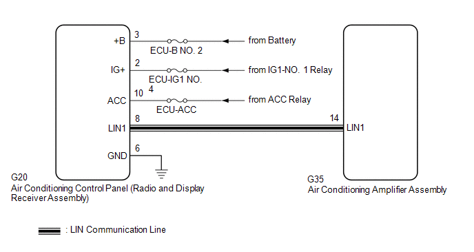
The air conditioning control panel (radio and display receiver assembly) communicates with the air conditioning amplifier assembly via LIN communication.
If a malfunction occurs in the LIN communication system, the air conditioning amplifier assembly will not operate, even if the air conditioning control panel (radio and display receiver assembly) is operated.
|
DTC No. | Detection Item |
DTC Detection Condition | Trouble Area |
Memory |
|---|---|---|---|---|
| B14B2 |
Lost Communication with Front Panel LIN |
Lost communication with air conditioning control assembly |
| Memorized (10 sec. or more)* |
WIRING DIAGRAM
CAUTION / NOTICE / HINT
NOTICE:
Inspect the fuses for circuits related to this system before performing the following procedure.
PROCEDURE
| 1. |
CHECK HARNESS AND CONNECTOR (AIR CONDITIONING CONTROL PANEL (RADIO AND DISPLAY RECEIVER ASSEMBLY) - POWER SOURCE AND BODY GROUND) |
(a) Disconnect the G20 air conditioning control panel (radio and display receiver assembly) connector.
(b) Measure the voltage and resistance according to the value(s) in the table below.
Standard Voltage:
|
Tester Connection | Condition |
Specified Condition |
|---|---|---|
|
G20-3 (+B) - Body ground |
Engine switch off | 11 to 14 V |
|
G20-2 (IG+) - Body ground |
Engine switch on (IG) |
11 to 14 V |
|
G20-10 (ACC) - Body ground |
Engine switch on (ACC) |
11 to 14 V |
Standard Resistance:
|
Tester Connection | Condition |
Specified Condition |
|---|---|---|
|
G20-6 (GND) - Body ground |
Always | Below 1 Ω |
| NG |  | REPAIR OR REPLACE HARNESS OR CONNECTOR |
|
| 2. |
CHECK HARNESS AND CONNECTOR (AIR CONDITIONING CONTROL PANEL (RADIO AND DISPLAY RECEIVER ASSEMBLY) - AIR CONDITIONING AMPLIFIER ASSEMBLY) |
(a) Disconnect the G35 air conditioning amplifier assembly connector.
(b) Measure the resistance according to the value(s) in the table below.
Standard Resistance:
|
Tester Connection | Condition |
Specified Condition |
|---|---|---|
|
G20-8 (LIN1) - G35-14 (LIN1) |
Always | Below 1 Ω |
|
G20-8 (LIN1) or G35-14 (LIN1) - Other terminals and body ground |
Always | 10 kΩ or higher |
| NG | | REPAIR OR REPLACE HARNESS OR CONNECTOR |
|
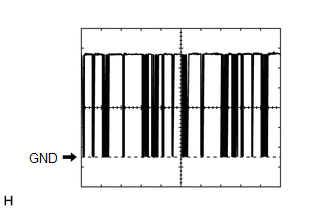
| 3. |
INSPECT AIR CONDITIONING AMPLIFIER ASSEMBLY |
(a) Connect the G35 air conditioning amplifier assembly connector.
(b) Turn the engine switch on (IG).
(c) Using an oscilloscope, check the waveform.
|
Item | Content |
|---|---|
|
Terminal No. | G35-14 (LIN1) - Body ground |
|
Tool Setting | 2 V/DIV., 20 ms./DIV. |
|
Condition | Engine switch on (IG) |
OK:
Waveform is similar to that shown in the illustration.
| NG | | REPLACE AIR CONDITIONING AMPLIFIER ASSEMBLY |
|
| 4. |
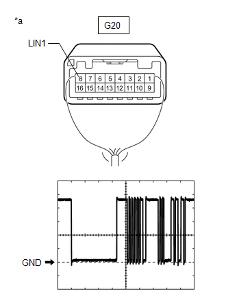
INSPECT AIR CONDITIONING CONTROL PANEL (RADIO AND DISPLAY RECEIVER ASSEMBLY) |
|
*a | Component with harness connected (Air Conditioning Control Panel (Radio and Display Receiver Assembly)) |
(a) Connect the G20 air conditioning control panel (radio and display receiver assembly) connector.
(b) Turn the engine switch on (IG).
(c) Using an oscilloscope, check the waveform.
|
Item | Content |
|---|---|
|
Terminal No. | G20-8 (LIN1) - Body ground |
|
Tool Setting | 2 V/DIV., 20 ms./DIV. |
|
Condition | Engine switch on (IG) |
OK:
Waveform is similar to that shown in the illustration.
| OK | | REPLACE AIR CONDITIONING AMPLIFIER ASSEMBLY |
| NG | | REPLACE AIR CONDITIONING CONTROL PANEL (RADIO & DISPLAY RECEIVER ASSEMBLY) |
DESCRIPTION
This DTC is stored if the amount of refrigerant in the air conditioning system is insufficient.
The air conditioning amplifier assembly receives the ambient temperature signal, refrigerant pressure signal, etc. from various sensors.
Based on these signals, the air conditioning amplifier assembly detects the amount of refrigerant.
If the amount of refrigerant is insufficient, the A/C switch indicator will turn off and the air conditioning system will stop operating.
|
DTC No. | Detection Item |
DTC Detection Condition | Trouble Area |
Memory |
|---|---|---|---|---|
| B14B8 |
Refrigerant Shortage | The following condition is detected in the normal operation refrigerant shortage check: Amount of refrigerant is insufficient |
| Memorized (10 min. or more)* |
WIRING DIAGRAM

PROCEDURE
| 1. |
CHECK REFRIGERANT PRESSURE |
(a) Connect the Techstream to the DLC3.
(b) Turn the engine switch on (IG).
(c) Turn the Techstream on.
(d) Enter the following menus: Body Electrical / Air Conditioner / Data List.
(e) Read the Data List according to the display on the Techstream.
Body Electrical > Air Conditioner > Data List|
Tester Display | Measurement Item |
Range | Normal Condition |
Diagnostic Note |
|---|---|---|---|---|
|
Regulator Pressure Sensor |
Air conditioner pressure sensor |
Min.: -66.2 psi (gauge) Max.: 478.0 psi (gauge) |
Actual refrigerant pressure displayed |
|
|
Tester Display |
|---|
| Regulator Pressure Sensor |
(f) Install a manifold gauge set.
Click here

(g) Read the manifold gauge set with the following conditions met.
Measurement Condition:|
Item | Condition |
|---|---|
|
Vehicle doors | Fully open |
|
Temperature setting | MAX COLD |
|
Blower speed | HI |
|
A/C switch | On |
|
Recirculation/fresh switch |
RECIRCULATION |
|
Interior temperature |
30 to 35°C (86 to 95°F) |
Standard Pressure:
Low pressure side
150 to 250 kPa (1.5 to 2.5 kgf/cm2, 22 to 36 psi)
High pressure side
1370 to 1570 kPa (14 to 16 kgf/cm2, 199 to 228 psi)
(h) Compare the values displayed in the Data List and on the manifold gauge set.
OK:
The values displayed in the Data List and on the manifold gauge set match.
| OK |  | INSPECT REFRIGERANT PRESSURE WITH MANIFOLD GAUGE SET |
|
| 2. |
CHECK HARNESS AND CONNECTOR (POWER SOURCE CIRCUIT) |
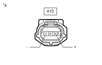
|
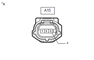
*a | Front view of wire harness connector (to Air Conditioner Pressure Sensor) |
(a) Disconnect the A15 air conditioner pressure sensor connector.
(b) Measure the voltage according to the value(s) in the table below.
Standard Voltage:
|
Tester Connection | Condition |
Specified Condition |
|---|---|---|
|
A15-3 (+) - Body ground |
Engine switch on (IG) |
4.75 to 5.25 V |
| NG | | GO TO STEP 7 |
|
| 3. |
CHECK HARNESS AND CONNECTOR (AIR CONDITIONER PRESSURE SENSOR - BODY GROUND) |

|
*a | Front view of wire harness connector (to Air Conditioner Pressure Sensor) |
(a) Measure the resistance according to the value(s) in the table below.
Standard Resistance:
|
Tester Connection | Condition |
Specified Condition |
|---|---|---|
|
A15-1 (-) - Body ground |
Always | Below 1 Ω |
| NG | | GO TO STEP 6 |
|
| 4. |
CHECK HARNESS AND CONNECTOR (AIR CONDITIONER PRESSURE SENSOR - AIR CONDITIONING AMPLIFIER ASSEMBLY) |
(a) Disconnect the G36 air conditioning amplifier assembly connector.
(b) Measure the resistance according to the value(s) in the table below.
Standard Resistance:
|
Tester Connection | Condition |
Specified Condition |
|---|---|---|
|
A15-2 (PR) - G36-24 (PRE) |
Always | Below 1 Ω |
|
A15-2 (PR) or G36-24 (PRE) - Other terminals and body ground |
Always | 10 kΩ or higher |
| NG | | REPAIR OR REPLACE HARNESS OR CONNECTOR |
|
| 5. |
INSPECT AIR CONDITIONER PRESSURE SENSOR (SENSOR SIGNAL CIRCUIT) |
|
*a | Component with harness connected (Air Conditioning Amplifier Assembly) |
(a) Measure the voltage with the following conditions met.
Measurement Condition:|
Item | Condition |
|---|---|
|
Vehicle doors | Fully open |
|
Temperature setting | MAX COLD |
|
Blower speed | HI |
|
A/C switch | On |
|
Recirculation/fresh switch |
RECIRCULATION |
|
Interior temperature |
25 to 35°C (77 to 95°F) |
NOTICE:
HINT:
When the ambient air temperature is low (below -1.5°C (29.3°F)), the compressor with pulley will be stopped, due to inputs of the thermistor assembly and No. 1 cooler thermistor, to prevent the evaporator from freezing. In this case, perform the inspection in a warm indoor environment.
(1) Measure the voltage according to the value(s) in the table below.
Standard Voltage:
|
Tester Connection | Condition |
Specified Condition |
|---|---|---|
|
G36-24 (PRE) - Body ground |
Engine switch on (IG) (A/C switch: On) |
0.74 to 4.61 V |
(b) Connect the Techstream to the DLC3.
(c) Turn the engine switch on (IG).
(d) Turn the Techstream on.
(e) Enter the following menus: Body Electrical / Air Conditioner / Data List.
(f) Read the Data List according to the display on the Techstream.
Body Electrical > Air Conditioner > Data List|
Tester Display | Measurement Item |
Range | Normal Condition |
Diagnostic Note |
|---|---|---|---|---|
|
Regulator Pressure Sensor |
Air conditioner pressure sensor |
Min.: -66.2 psi (gauge) Max.: 478.0 psi (gauge) |
Actual refrigerant pressure displayed |
|
|
Tester Display |
|---|
| Regulator Pressure Sensor |
OK:
The voltage and value displayed in the Data List change.
|
Result | Proceed to |
|---|---|
|
OK | A |
|
NG (The voltage changes but the value displayed in the Data List does not change.) | |
|
NG (The voltage does not change.) |
B |
| A |
| REPLACE AIR CONDITIONING AMPLIFIER ASSEMBLY |
| B |
| REPLACE AIR CONDITIONER PRESSURE SENSOR |
| 6. |
CHECK HARNESS AND CONNECTOR (AIR CONDITIONER PRESSURE SENSOR - AIR CONDITIONING AMPLIFIER ASSEMBLY) |
(a) Disconnect the G36 air conditioning amplifier assembly connector.
(b) Measure the resistance according to the value(s) in the table below.
Standard Resistance:
|
Tester Connection | Condition |
Specified Condition |
|---|---|---|
|
A15-1 (-) - G36-3 (SG-4) |
Always | Below 1 Ω |
|
A15-1 (-) or G36-3 (SG-4) - Other terminals and body ground |
Always | 10 kΩ or higher |
| OK | | REPLACE AIR CONDITIONING AMPLIFIER ASSEMBLY |
| NG | | REPAIR OR REPLACE HARNESS OR CONNECTOR |
| 7. |
CHECK HARNESS AND CONNECTOR (AIR CONDITIONER PRESSURE SENSOR - AIR CONDITIONING AMPLIFIER ASSEMBLY) |
(a) Disconnect the G36 air conditioning amplifier assembly connector.
(b) Measure the resistance according to the value(s) in the table below.
Standard Resistance:
|
Tester Connection | Condition |
Specified Condition |
|---|---|---|
|
A15-3 (+) - G36-6 (S5-3) |
Always | Below 1 Ω |
|
A15-3 (+) or G36-6 (S5-3) - Other terminals and body ground |
Always | 10 kΩ or higher |
| OK | | REPLACE AIR CONDITIONING AMPLIFIER ASSEMBLY |
| NG | | REPAIR OR REPLACE HARNESS OR CONNECTOR |
DESCRIPTION
This DTC is stored if the amount of refrigerant in the in the air conditioning system exceeds a threshold. The air conditioning amplifier assembly judges whether the amount of refrigerant is appropriate based on the detected refrigerant pressure and cooler compressor assembly operation current. If the amount of refrigerant in the system is determined to have exceeded a threshold, operation of the cooler compressor assembly will be stopped, and will remain stopped even if the engine switch is turned off and then the engine is restarted.
|
DTC No. | Detection Item |
DTC Detection Condition | Trouble Area |
Memory |
|---|---|---|---|---|
| B14BD |
Refrigerant Overabundance Filling Malfunction |
All of the following conditions are met 2 times or more in the same trip:
|
| Memorized (60 sec. or more)* |

|
*a | Electric Current (mA) |
*b | Refrigerant Pressure kPa (kgf/cm2, psi) |
PROCEDURE
| 1. |
RECOVER REFRIGERANT FROM REFRIGERATION SYSTEM |
(a) Recover the refrigerant from the air conditioning system using a refrigerant recovery unit.
Click here 
|
| 2. |
CHARGE AIR CONDITIONING SYSTEM WITH REFRIGERANT |
(a) Charge the air conditioning system with refrigerant.
Click here
| NEXT |  |
END |
DESCRIPTION
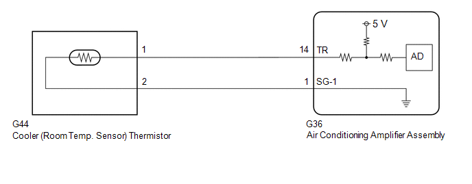
The cooler (room temp. sensor) thermistor is installed in the instrument panel to detect the cabin temperature, which is used to control the air conditioning system. The resistance of the cooler (room temp. sensor) thermistor changes in accordance with the cabin temperature. As the temperature decreases, the resistance increases. As the temperature increases, the resistance decreases.
The air conditioning amplifier assembly applies voltage (5 V) to the cooler (room temp. sensor) thermistor and reads voltage changes due to changes in the resistance of the cooler (room temp. sensor) thermistor.
|
DTC No. | Detection Item |
DTC Detection Condition | Trouble Area |
Memory |
|---|---|---|---|---|
| B1411 |
Room Temperature Sensor Circuit |
Open or short in room temperature sensor circuit |
| Memorized (4 sec. or more)* |
HINT:
If the cabin temperature is approximately -18.6°C (-1.48°F) or lower, DTC B1411 may be stored even though the system is normal.
WIRING DIAGRAM
PROCEDURE
| 1. |
READ VALUE USING TECHSTREAM |
(a) Connect the Techstream to the DLC3.
(b) Turn the engine switch on (IG).
(c) Turn the Techstream on.
(d) Enter the following menus: Body Electrical / Air Conditioner / Data List.
(e) Read the Data List according to the display on the Techstream.
Body Electrical > Air Conditioner > Data List|
Tester Display | Measurement Item |
Range | Normal Condition |
Diagnostic Note |
|---|---|---|---|---|
|
Room Temperature Sensor |
Cooler (room temp. sensor) thermistor |
Min.: -6.50°C (20.30°F) Max.: 57.25°C (135.05°F) |
Actual cabin temperature displayed |
Cooler (room temp. sensor) thermistor circuit malfunction
|
|
Tester Display |
|---|
| Room Temperature Sensor |
OK:
The display is as specified in the normal condition column.
| OK |  | REPLACE AIR CONDITIONING AMPLIFIER ASSEMBLY |
|
| 2. |
INSPECT COOLER (ROOM TEMP. SENSOR) THERMISTOR |
(a) Remove the cooler (room temp. sensor) thermistor.
Click here

(b) Inspect the cooler (room temp. sensor) thermistor.
Click here
| NG | | REPLACE COOLER (ROOM TEMP. SENSOR) THERMISTOR |
|
| 3. |
CHECK HARNESS AND CONNECTOR (COOLER (ROOM TEMP. SENSOR) THERMISTOR - AIR CONDITIONING AMPLIFIER ASSEMBLY) |
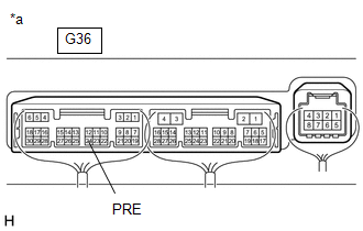
(a) Disconnect the G36 air conditioning amplifier assembly connector.
(b) Measure the resistance according to the value(s) in the table below.
Standard Resistance:
|
Tester Connection | Condition |
Specified Condition |
|---|---|---|
|
G44-1 - G36-14 (TR) | Always |
Below 1 Ω |
|
G44-2 - G36-1 (SG-1) |
Always | Below 1 Ω |
|
G44-1 or G36-14 (TR) - Other terminals and body ground |
Always | 10 kΩ or higher |
|
G44-2 or G36-1 (SG-1) - Other terminals and body ground |
Always | 10 kΩ or higher |
| OK | | REPLACE AIR CONDITIONING AMPLIFIER ASSEMBLY |
| NG | | REPAIR OR REPLACE HARNESS OR CONNECTOR |
DESCRIPTION
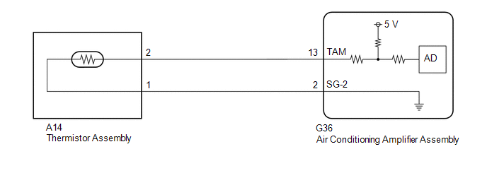
The thermistor assembly is installed in front of the cooler condenser assembly to detect the ambient temperature, which is used to control the air conditioning system. This sensor is connected to the air conditioning amplifier assembly and detects fluctuations in the ambient temperature. This data is used for controlling the cabin temperature. The sensor sends a signal to the air conditioning amplifier assembly. The resistance of the thermistor assembly changes in accordance with the ambient temperature. As the temperature decreases, the resistance increases. As the temperature increases, the resistance decreases.
The air conditioning amplifier assembly applies voltage (5 V) to the thermistor assembly and reads voltage changes due to changes in the resistance of the thermistor assembly.
|
DTC No. | Detection Item |
DTC Detection Condition | Trouble Area |
Memory |
|---|---|---|---|---|
| B1412 |
Ambient Temperature Sensor Circuit |
Open or short in ambient temperature sensor circuit |
| Memorized (4 sec. or more)* |
HINT:
If the ambient temperature is approximately -52.9°C (-63.22°F) or lower, DTC B1412 may be stored even though the system is normal.
WIRING DIAGRAM
PROCEDURE
| 1. |
READ VALUE USING TECHSTREAM |
(a) Connect the Techstream to the DLC3.
(b) Turn the engine switch on (IG).
(c) Turn the Techstream on.
(d) Enter the following menus: Body Electrical / Air Conditioner / Data List.
(e) Read the Data List according to the display on the Techstream.
Body Electrical > Air Conditioner > Data List|
Tester Display | Measurement Item |
Range | Normal Condition |
Diagnostic Note |
|---|---|---|---|---|
|
Ambient Temp Sensor | Thermistor assembly |
Min.: -23.30°C (-9.94°F) Max.: 65.95°C (150.71°F) |
Actual ambient temperature displayed |
Thermistor assembly circuit malfunction
|
|
Tester Display |
|---|
| Ambient Temp Sensor |
OK:
The display is as specified in the normal condition column.
| OK |  | REPLACE AIR CONDITIONING AMPLIFIER ASSEMBLY |
|
| 2. |
INSPECT THERMISTOR ASSEMBLY |
(a) Remove the thermistor assembly.
Click here 
(b) Inspect the thermistor assembly.
Click here
| NG | | REPLACE THERMISTOR ASSEMBLY |
|
| 3. |
CHECK HARNESS AND CONNECTOR (THERMISTOR ASSEMBLY - AIR CONDITIONING AMPLIFIER ASSEMBLY) |
(a) Disconnect the G36 air conditioning amplifier assembly connector.
(b) Measure the resistance according to the value(s) in the table below.
Standard Resistance:
|
Tester Connection | Condition |
Specified Condition |
|---|---|---|
|
A14-2 - G36-13 (TAM) |
Always | Below 1 Ω |
|
A14-1 - G36-2 (SG-2) |
Always | Below 1 Ω |
|
A14-2 or G36-13 (TAM) - Other terminals and body ground |
Always | 10 kΩ or higher |
|
A14-1 or G36-2 (SG-2) - Other terminals and body ground |
Always | 10 kΩ or higher |
| OK | | REPLACE AIR CONDITIONING AMPLIFIER ASSEMBLY |
| NG | | REPAIR OR REPLACE HARNESS OR CONNECTOR |
DESCRIPTION
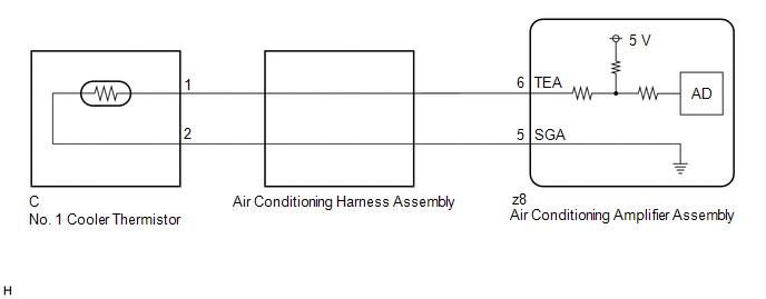
The No. 1 cooler thermistor is installed to the evaporator in the air conditioner unit to detect the temperature of the cooled air that has passed through the evaporator, which is used to control the air conditioning system. It sends signals to the air conditioning amplifier assembly. The resistance of the No. 1 cooler thermistor changes in accordance with the temperature of the cooled air that has passed through the evaporator. As the temperature decreases, the resistance increases. As the temperature increases, the resistance decreases.
The air conditioning amplifier assembly applies voltage (5 V) to the No. 1 cooler thermistor and reads voltage changes as the resistance of the No. 1 cooler thermistor changes. This sensor is used for frost prevention.
|
DTC No. | Detection Item |
DTC Detection Condition | Trouble Area |
Memory |
|---|---|---|---|---|
| B1413 |
Evaporator Temperature Circuit or Evaporator Fin Thermistor |
Open or short in evaporator temperature sensor circuit |
| Memorized (4 sec. or more)* |
WIRING DIAGRAM
PROCEDURE
| 1. |
READ VALUE USING TECHSTREAM |
(a) Connect the Techstream to the DLC3.
(b) Turn the engine switch on (IG)
(c) Turn the Techstream on.
(d) Enter the following menus: Body Electrical / Air Conditioner / Data List.
(e) Read the Data List according to the display on the Techstream.
Body Electrical > Air Conditioner > Data List|
Tester Display | Measurement Item |
Range | Normal Condition |
Diagnostic Note |
|---|---|---|---|---|
|
Evaporator Fin Thermistor |
No. 1 cooler thermistor |
Min.: -29.70°C (-21.46°F) Max.: 59.55°C (139.19°F) |
Actual evaporator temperature displayed |
No. 1 cooler thermistor circuit malfunction
|
|
Tester Display |
|---|
| Evaporator Fin Thermistor |
OK:
The display is as specified in the normal condition column.
| OK |  | REPLACE AIR CONDITIONING AMPLIFIER ASSEMBLY |
|
| 2. |
INSPECT NO. 1 COOLER THERMISTOR |
(a) Remove the No. 1 cooler thermistor.
Click here 
(b) Inspect the No. 1 cooler thermistor.
Click here
| NG | | REPLACE NO. 1 COOLER THERMISTOR |
|
| 3. |
INSPECT AIR CONDITIONING HARNESS ASSEMBLY |
|
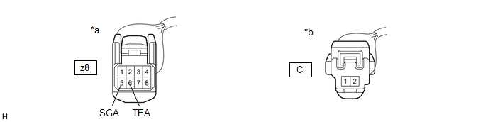
*a | Front view of wire harness connector (to Air Conditioning Amplifier Assembly) |
*b | Front view of wire harness connector (to No. 1 Cooler Thermistor) |
(a) Remove the air conditioning harness assembly.
Click here
(b) Measure the resistance according to the value(s) in the table below.
Standard Resistance:
|
Tester Connection | Condition |
Specified Condition |
|---|---|---|
|
z8-5 (SGA) - C-2 | Always |
Below 1 Ω |
|
z8-6 (TEA) - C-1 | Always |
Below 1 Ω |
| OK | | REPLACE AIR CONDITIONING AMPLIFIER ASSEMBLY |
| NG | | REPLACE AIR CONDITIONING HARNESS ASSEMBLY |
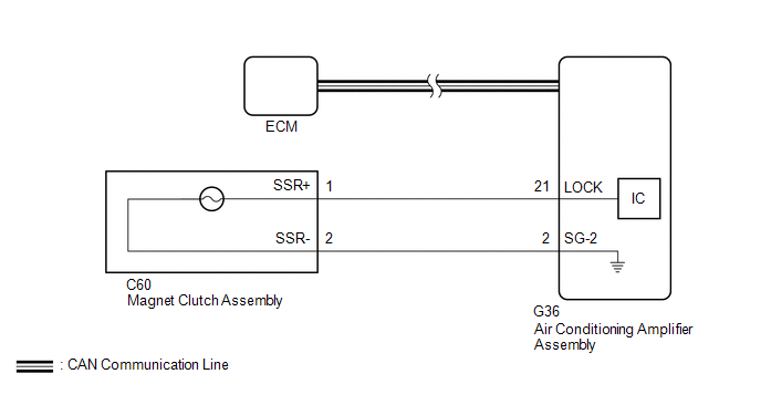
DESCRIPTION
The ECM sends the engine speed signal to the air conditioning amplifier assembly via CAN communication.
The air conditioning amplifier assembly reads the difference between compressor speed and engine speed. If the difference becomes excessively large, the air conditioning amplifier assembly determines that the compressor is locked, and turns the magnet clutch assembly off.
|
DTC No. | Detection Item |
DTC Detection Condition | Trouble Area |
Memory |
|---|---|---|---|---|
| B1422 |
Compressor Lock | Open or short in A/C lock sensor circuit |
| Memorized (3 seconds or more) |
HINT:
The air conditioning amplifier assembly stores the DTC if the malfunction has occurred for the period of time indicated in the brackets.
WIRING DIAGRAM
CAUTION / NOTICE / HINT
NOTICE:
Click here 
Click here
Click here
PROCEDURE
|
1. | INSPECT MAGNET CLUTCH ASSEMBLY |
(a) Remove the compressor assembly with magnetic clutch.
Click here
(b) Inspect the magnet clutch assembly.
Click here
| NG |  | REPLACE MAGNET CLUTCH ASSEMBLY |
|
| 2. |
CHECK HARNESS AND CONNECTOR (MAGNET CLUTCH ASSEMBLY - AIR CONDITIONING AMPLIFIER ASSEMBLY) |
(a) Disconnect the G36 air conditioning amplifier assembly connector.
(b) Measure the resistance according to the value(s) in the table below.
Standard Resistance:
|
Tester Connection | Condition |
Specified Condition |
|---|---|---|
|
C60-1 (SSR+) - G36-21 (LOCK) |
Always | Below 1 Ω |
|
C60-2 (SSR-) - G36-2 (SG-2) |
Always | Below 1 Ω |
|
C60-1 (SSR+) or G36-21 (LOCK) - Other terminals and body ground |
Always | 10 kΩ or higher |
|
C60-2 (SSR-) or G36-2 (SG-2) - Other terminals and body ground |
Always | 10 kΩ or higher |
| OK | | REPLACE AIR CONDITIONING AMPLIFIER ASSEMBLY |
| NG | | REPAIR OR REPLACE HARNESS OR CONNECTOR |
DESCRIPTION
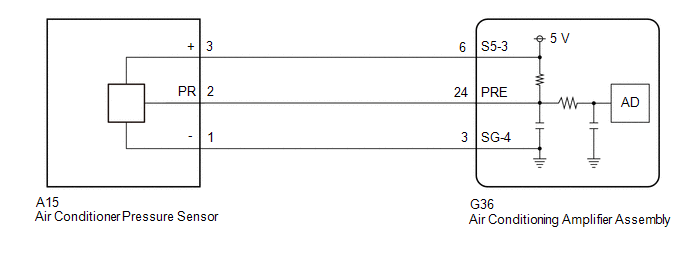
This DTC is stored if refrigerant pressure on the high pressure side is extremely low (176 kPa (1.8 kgf/cm2, 26 psi) or less) or extremely high (3025 kPa (30.8 kgf/cm2, 439 psi) or more). The air conditioner pressure sensor, which is installed to the high pressure side pipe to detect refrigerant pressure, sends a refrigerant pressure signal to the air conditioning amplifier assembly. The air conditioning amplifier assembly converts this signal to a pressure value according to the sensor characteristics and uses it to control the compressor.
|
DTC No. | Detection Item |
DTC Detection Condition | Trouble Area |
Memory |
|---|---|---|---|---|
| B1423 |
Open in Pressure Sensor Circuit / Abnormal Refrigerant Pressure |
|
| - |
WIRING DIAGRAM
CAUTION / NOTICE / HINT
HINT:
If DTC B1423 and B14B8 are output at the same time, troubleshoot for DTC B14B8 first.
Click here 
PROCEDURE
| 1. |
PERFORM REFRIGERANT SHORTAGE CHECK |
(a) Connect the Techstream to the DLC3.
(b) Turn the engine switch on (IG).
(c) Turn the Techstream on.
(d) Enter the following menus: Body Electrical / Air Conditioner / Utility / Refrigerant Gas Volume Check.
Body Electrical > Air Conditioner > Utility|
Tester Display |
|---|
| Refrigerant Gas Volume Check |
(e) Check that the following conditions are met and perform the refrigerant shortage check according to the display on the Techstream.
Measurement Condition:|
Item | Condition |
|---|---|
|
A/C switch | On |
|
Ambient temperature* |
0 to 49°C (32 to 120°F) |
|
Blower speed | HI |
*: If the ambient temperature is not within the range shown, do not perform this check.
|
Result | Amount of Refrigerant |
|---|---|
|
Refrigerant correct | Correct |
|
Refrigerant shortage |
Insufficient |
OK:
"Refrigerant correct" is displayed on the Techstream.
| NG |  | GO TO STEP 14 |
|
| 2. |
CHECK REFRIGERANT PRESSURE |
(a) Connect the Techstream to the DLC3.
(b) Turn the engine switch on (IG).
(c) Turn the Techstream on.
(d) Enter the following menus: Body Electrical / Air Conditioner / Data List.
(e) Read the Data List according to the display on the Techstream.
Body Electrical > Air Conditioner > Data List|
Tester Display | Measurement Item |
Range | Normal Condition |
Diagnostic Note |
|---|---|---|---|---|
|
Regulator Pressure Sensor |
Air conditioner pressure sensor |
Min.: -66.2 psi (gauge) Max.: 478.0 psi (gauge) |
Actual refrigerant pressure displayed |
|
|
Tester Display |
|---|
| Regulator Pressure Sensor |
(f) Install a manifold gauge set.
Click here
(g) Read the manifold gauge set with the following conditions met.
Measurement Condition:|
Item | Condition |
|---|---|
|
Vehicle doors | Fully open |
|
Temperature setting | MAX COLD |
|
Blower speed | HI |
|
A/C switch | On |
|
Recirculation/fresh switch |
RECIRCULATION |
|
Interior temperature |
25 to 35°C (77 to 95°F) |
Standard Pressure:
Low pressure side
150 to 250 kPa (1.5 to 2.5 kgf/cm2, 22 to 36 psi)
High pressure side
1370 to 1570 kPa (14 to 16 kgf/cm2, 199 to 228 psi)
(h) Compare the values displayed in the Data List and on the manifold gauge set.
OK:
The values displayed in the Data List and on the manifold gauge set match.
| NG | | GO TO STEP 8 |
|
| 3. |
CHECK REFRIGERANT HIGH PRESSURE HISTORY |
(a) Connect the Techstream to the DLC3.
(b) Turn the engine switch on (IG).
(c) Enter the following menus: Body Electrical / Air Conditioner / Data List.
(d) Read the Data List according to the display on the Techstream.
Body Electrical > Air Conditioner > Data List|
Tester Display | Measurement Item |
Range | Normal Condition |
Diagnostic Note |
|---|---|---|---|---|
|
Refrigerant High Pressure History |
Refrigerant high pressure history |
Min.: 0 Max.: 255 |
Number of times refrigerant high pressure history stored displayed |
- |
|
Tester Display |
|---|
| Refrigerant High Pressure History |
|
Result | Proceed to |
|---|---|
|
The value is 0 | A |
|
The value is not 0 | B |
| A |
| INSPECT REFRIGERANT PRESSURE WITH MANIFOLD GAUGE SET |
|
| 4. |
INSPECT COOLING FAN SYSTEM |
(a) Check if the cooling fan operates normally.
Click here
| NG | | GO TO COOLING FAN SYSTEM |
|
| 5. |
RECOVER REFRIGERANT FROM REFRIGERATION SYSTEM |
(a) Recover the refrigerant from the air conditioning system using a refrigerant recovery unit.
Click here
|
| 6. |
CHARGE AIR CONDITIONING SYSTEM WITH REFRIGERANT |
Click here
|
| 7. |
PERFORM REFRIGERANT HIGH PRESSURE HISTORY CLEAR |
(a) Clear the refrigerant high pressure history stored in the air conditioning amplifier assembly.
Click here
| NEXT | | END |
| 8. |
CHECK HARNESS AND CONNECTOR (POWER SOURCE CIRCUIT) |
|
*a | Front view of wire harness connector (to Air Conditioner Pressure Sensor) |
(a) Disconnect the A15 air conditioner pressure sensor connector.
(b) Measure the voltage according to the value(s) in the table below.
Standard Voltage:
|
Tester Connection | Condition |
Specified Condition |
|---|---|---|
|
A15-3 (+) - A15-1 (-) |
Engine switch on (IG) |
4.75 to 5.25 V |
| NG | | GO TO STEP 13 |
|
| 9. |
CHECK HARNESS AND CONNECTOR (AIR CONDITIONER PRESSURE SENSOR - BODY GROUND) |

|
*a | Front view of wire harness connector (to Air Conditioner Pressure Sensor) |
(a) Measure the resistance according to the value(s) in the table below.
Standard Resistance:
|
Tester Connection | Condition |
Specified Condition |
|---|---|---|
|
A15-1 (-) - Body ground |
Always | Below 1 Ω |
| NG | | GO TO STEP 12 |
|
| 10. |
CHECK HARNESS AND CONNECTOR (AIR CONDITIONER PRESSURE SENSOR - AIR CONDITIONING AMPLIFIER ASSEMBLY) |
(a) Disconnect the G36 air conditioning amplifier assembly connector.
(b) Measure the resistance according to the value(s) in the table below.
Standard Resistance:
|
Tester Connection | Condition |
Specified Condition |
|---|---|---|
|
A15-2 (PR) - G36-24 (PRE) |
Always | Below 1 Ω |
|
A15-2 (PR) or G36-24 (PRE) - Other terminals and body ground |
Always | 10 kΩ or higher |
| NG | | REPAIR OR REPLACE HARNESS OR CONNECTOR |
|
| 11. |
INSPECT AIR CONDITIONER PRESSURE SENSOR (SENSOR SIGNAL CIRCUIT) |

|
*a | Component with harness connected (Air Conditioning Amplifier Assembly) |
(a) Measure the voltage with the following conditions met.
Measurement Condition:|
Item | Condition |
|---|---|
|
Vehicle doors | Fully open |
|
Temperature setting | MAX COLD |
|
Blower speed | HI |
|
A/C switch | On |
|
Recirculation/fresh switch |
RECIRCULATION |
|
Interior temperature |
25 to 35°C (77 to 95°F) |
NOTICE:
HINT:
When the ambient air temperature is low(below -1.5°C (29.3°F)), the compressor with pulley will be stopped, due to inputs of the thermistor assembly and No. 1 cooler thermistor, to prevent the evaporator from freezing. In this case, perform the inspection in a warm indoor environment.
(1) Measure the voltage according to the value(s) in the table below.
Standard Voltage:
|
Tester Connection | Condition |
Specified Condition |
|---|---|---|
|
G36-24 (PRE) - Body ground |
Engine switch on (IG) (A/C switch: On) |
0.74 to 4.61 V |
(b) Connect the Techstream to the DLC3.
(c) Turn the engine switch on (IG).
(d) Turn the Techstream on.
(e) Enter the following menus: Body Electrical / Air Conditioner / Data List.
(f) Read the Data List according to the display on the Techstream.
Body Electrical > Air Conditioner > Data List|
Tester Display | Measurement Item |
Range | Normal Condition |
Diagnostic Note |
|---|---|---|---|---|
|
Regulator Pressure Sensor |
Air conditioner pressure sensor |
Min.: -66.2 psi (gauge) Max.: 478.0 psi (gauge) |
Actual refrigerant pressure displayed |
|
|
Tester Display |
|---|
| Regulator Pressure Sensor |
OK:
The voltage and value displayed in the Data List change.
|
Result | Proceed to |
|---|---|
|
OK | A |
|
NG (The voltage changes but the value displayed in the Data List does not change.) | |
|
NG (The voltage does not change.) |
B |
| A |
| REPLACE AIR CONDITIONING AMPLIFIER ASSEMBLY |
| B |
| REPLACE AIR CONDITIONER PRESSURE SENSOR |
| 12. |
CHECK HARNESS AND CONNECTOR (AIR CONDITIONER PRESSURE SENSOR - AIR CONDITIONING AMPLIFIER ASSEMBLY) |
(a) Disconnect the G36 air conditioning amplifier assembly connector.
(b) Measure the resistance according to the value(s) in the table below.
Standard Resistance:
|
Tester Connection | Condition |
Specified Condition |
|---|---|---|
|
A15-1 (-) - G36-3 (SG-4) |
Always | Below 1 Ω |
|
A15-1 (-) or G36-3 (SG-4) - Other terminals and body ground |
Always | 10 kΩ or higher |
| OK | | REPLACE AIR CONDITIONING AMPLIFIER ASSEMBLY |
| NG | | REPAIR OR REPLACE HARNESS OR CONNECTOR |
| 13. |
CHECK HARNESS AND CONNECTOR (AIR CONDITIONER PRESSURE SENSOR - AIR CONDITIONING AMPLIFIER ASSEMBLY) |
(a) Disconnect the G36 air conditioning amplifier assembly connector.
(b) Measure the resistance according to the value(s) in the table below.
Standard Resistance:
|
Tester Connection | Condition |
Specified Condition |
|---|---|---|
|
A15-3 (+) - G36-6 (S5-3) |
Always | Below 1 Ω |
|
A15-3 (+) or G36-6 (S5-3) - Other terminals and body ground |
Always | 10 kΩ or higher |
| OK | | REPLACE AIR CONDITIONING AMPLIFIER ASSEMBLY |
| NG | | REPAIR OR REPLACE HARNESS OR CONNECTOR |
| 14. |
REPAIR AIR CONDITIONING SYSTEM LEAK |
(a) Identify the area where refrigerant is leaking from.
Click here
(b) Repair the identified area of the air conditioning system.
(c) Evacuate the air conditioning system.
| NEXT | | CHARGE SYSTEM WITH REFRIGERANT |
DESCRIPTION
|
DTC No. | Detection Item |
DTC Detection Condition | Trouble Area |
Memory |
|---|---|---|---|---|
| B1441 |
Air Mix Damper Control Servo Motor Circuit (Passenger Side) |
Air mix damper position sensor value does not change even if air conditioning amplifier assembly operates No. 1 air conditioning radiator damper servo sub-assembly (front passenger side air mix) |
| Memorized (30 sec. or more)* |
|
B1443 | Air Outlet Damper Control Servo Motor Circuit |
Air outlet damper position sensor value does not change even if air conditioning amplifier assembly operates No. 1 air conditioning radiator damper servo sub-assembly (mode) |
| Memorized (30 sec. or more)* |
|
B1446 | Air Mix Damper Control Servo Motor Circuit (Driver Side) |
Air mix damper position sensor value does not change even if air conditioning amplifier assembly operates No. 1 air conditioning radiator damper servo sub-assembly (driver side air mix) |
| Memorized (30 sec. or more)* |
|
Vehicle Condition | |||
|---|---|---|---|
|
Pattern 1 | Pattern 2 | ||
|
Diagnosis Condition | No. 1 air conditioning radiator damper servo sub-assembly operating |
○ | ○ |
|
Malfunction | Damper servo operation request signals are output but the damper position sensor value does not change |
○ | - |
|
Damper servo operation request signals are output but the damper position sensor value is abnormal |
- | ○ | |
|
Detection Time | Continuously for 30 seconds or more |
Continuously for 30 seconds or more | |
|
Trip Count | 1 trip |
1 trip | |
HINT:
If the conditions of either of these patterns are detected, a DTC will be stored.
WIRING DIAGRAM

CAUTION / NOTICE / HINT
HINT:
Click here 
Click here
PROCEDURE
|
1. | CHECK FOR DTC |
(a) Check for DTCs.
Body Electrical > Air Conditioner > Trouble Codes|
Result | Proceed to |
|---|---|
|
Only B1497 is output |
A |
| B1441, B1442, B1443 and B1446 are output |
B |
| B1441, B1443 or B1446 is output |
C |
| A |
 | GO TO DTC B1497 |
| B |
| REPLACE NO. 1 AIR CONDITIONING RADIATOR DAMPER SERVO SUB-ASSEMBLY |
|
| 2. |
INSPECT NO. 1 AIR CONDITIONING RADIATOR DAMPER SERVO SUB-ASSEMBLY (INSTALLATION CONDITION) |
(a) Check that the No. 1 air conditioning radiator damper servo sub-assembly is installed correctly.
OK:
The No. 1 air conditioning radiator damper servo sub-assembly is installed correctly.
| NG | | INSTALL NO. 1 AIR CONDITIONING RADIATOR DAMPER SERVO SUB-ASSEMBLY CORRECTLY |
|
| 3. |
INSPECT NO. 1 AIR CONDITIONING RADIATOR DAMPER SERVO SUB-ASSEMBLY (MOTOR, LINK, DAMPER) |
(a) Check for a wire harness caught between the links of the motors and dampers.
OK:
No wire harnesses are caught between the links of the motors and dampers.
| NG | | REMOVE PINCHED WIRE HARNESS |
|
| 4. |
INSPECT AIR CONDITIONING RADIATOR ASSEMBLY (DAMPER) |
(a) Remove the No. 1 air conditioning radiator damper servo sub-assembly.
Click here
(b) Operate the dampers by hand.
OK:
The dampers are easily operated by hand.
| OK | | REPLACE NO. 1 AIR CONDITIONING RADIATOR DAMPER SERVO SUB-ASSEMBLY |
| NG | | REPLACE AIR CONDITIONING RADIATOR ASSEMBLY |
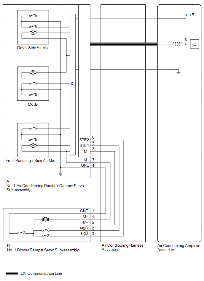
DESCRIPTION
The No. 1 blower damper servo sub-assembly sends pulse signals to inform the air conditioning amplifier assembly of the damper position. The air conditioning amplifier assembly activates the motor (normal or reverse) based on these signals to move the air inlet damper to the appropriate position to change the air inlet mode (fresh, recirculation/fresh, and recirculation).
The air conditioning amplifier assembly communicates with the servo through a communication/driver IC and wiring assembly called the air conditioning harness assembly.
|
DTC No. | Detection Item |
DTC Detection Condition | Trouble Area |
Memory |
|---|---|---|---|---|
| B1442 |
Air Inlet Damper Control Servo Motor |
Air inlet damper position sensor value does not change even if air conditioning amplifier assembly operates No. 1 blower damper servo sub-assembly |
| Memorized (30 sec. or more)* |
|
Vehicle Condition | |||
|---|---|---|---|
|
Pattern 1 | Pattern 2 | ||
|
Diagnosis Condition | No. 1 blower damper servo sub-assembly operating |
○ | ○ |
|
Malfunction | Air inlet damper servo operation request signals are output but the air inlet damper position sensor value does not change |
○ | - |
|
Air inlet damper servo operation request signals are output but the air inlet damper position sensor value is abnormal |
- | ○ | |
|
Detection Time | Continuously for 30 seconds or more |
Continuously for 30 seconds or more | |
|
Trip Count | 1 trip |
1 trip | |
HINT:
If the conditions of either of these patterns are detected, a DTC will be stored.
WIRING DIAGRAM
CAUTION / NOTICE / HINT
HINT:
Click here 
Click here
PROCEDURE
|
1. | CHECK FOR DTC |
(a) Check for DTCs.
Body Electrical > Air Conditioner > Trouble Codes|
Result | Proceed to |
|---|---|
|
Only B1497 is output |
A |
| B1441, B1442, B1443 and B1446 are output |
B |
| Only B1442 is output |
C |
| A |
 | GO TO DTC B1497 |
| B |
| REPLACE NO. 1 AIR CONDITIONING RADIATOR DAMPER SERVO SUB-ASSEMBLY |
|
| 2. |
INSPECT NO. 1 BLOWER DAMPER SERVO SUB-ASSEMBLY (INSTALLATION CONDITION) |
(a) Check that the No. 1 blower damper servo sub-assembly is installed correctly.
OK:
The No. 1 blower damper servo sub-assembly is installed correctly.
| NG | | INSTALL NO. 1 BLOWER DAMPER SERVO SUB-ASSEMBLY |
|
| 3. |
INSPECT NO. 1 BLOWER DAMPER SERVO SUB-ASSEMBLY (MOTOR, LINK, DAMPER) |
(a) Check for a wire harness caught between the links of the motors and dampers.
OK:
No wire harnesses are caught between the links of the motors and dampers.
| NG | | REMOVE PINCHED WIRE HARNESS |
|
| 4. |
INSPECT NO. 1 BLOWER DAMPER SERVO SUB-ASSEMBLY (DAMPER) |
(a) Remove the No. 1 blower damper servo sub-assembly.
Click here
(b) Operate the air inlet dampers by hand.
OK:
The air inlet dampers are easily operated by hand.
| NG | | REPLACE BLOWER ASSEMBLY |
|
| 5. |
INSPECT AIR CONDITIONING HARNESS ASSEMBLY |
(a) Disconnect the No. 1 air conditioning radiator damper servo sub-assembly connector.
(b) Measure the resistance according to the value(s) in the table below.
Standard Resistance:
|
Tester Connection | Condition |
Specified Condition |
|---|---|---|
|
A-6 (STE2) - B-3 (sigB) |
Always | Below 1 Ω |
|
A-5 (STE1) - B-2 (sigA) |
Always | Below 1 Ω |
|
A-8 (M-) - B-5 (M-) | Always |
Below 1 Ω |
|
A-7 (M+) - B-4 (M+) | Always |
Below 1 Ω |
|
A-4 (GND) - B-1 (GND) |
Always | Below 1 Ω |
|
A-6 (STE2) or B-3 (sigB) - Other terminals and Body ground |
Always | 10 kΩ or higher |
|
A-5 (STE1) or B-2 (sigA) - Other terminals and Body ground |
Always | 10 kΩ or higher |
|
A-8 (M-) or B-5 (M-) - Other terminals and Body ground |
Always | 10 kΩ or higher |
|
A-7 (M+) or B-4 (M+) - Other terminals and Body ground |
Always | 10 kΩ or higher |
| NG | | REPLACE AIR CONDITIONING HARNESS ASSEMBLY |
|
| 6. |
PERFORM ACTIVE TEST USING TECHSTREAM |
(a) Connect the No. 1 air conditioning radiator damper servo sub-assembly connector.
(b) Remove the No. 2 air conditioning radiator damper servo sub-assembly.
Click here
(c) Connect the No. 1 blower damper servo sub-assembly connector to the No. 2 air conditioning radiator damper servo sub-assembly.
(d) Connect the Techstream to the DLC3.
(e) Turn the engine switch on (IG).
(f) Turn the Techstream on.
(g) Enter the following menus: Body Electrical / Air Conditioner / Active Test.
(h) Perform the Active Test according to the display on the Techstream.
Body Electrical > Air Conditioner > Active Test|
Tester Display | Measurement Item |
Control Range | Diagnostic Note |
|---|---|---|---|
|
Air Inlet Damper Targ Pulse |
No. 1 blower damper servo sub-assembly pulse* |
Min.: 128 Max.: 383 |
Operates between 220 and 256 pulses |
|
Tester Display |
|---|
| Air Inlet Damper Targ Pulse |
OK:
The No. 2 air conditioning radiator damper servo sub-assembly operates.
| OK | | REPLACE NO. 1 BLOWER DAMPER SERVO SUB-ASSEMBLY |
| NG | | REPLACE NO. 1 AIR CONDITIONING RADIATOR DAMPER SERVO SUB-ASSEMBLY |
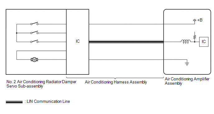
DESCRIPTION
The No. 2 air conditioning radiator damper servo sub-assembly sends pulse signals to inform the air conditioning amplifier assembly of the damper position. The air conditioning amplifier assembly activates the motor (normal or reverse) based on these signals to move the air outlet damper to the appropriate position, which controls the rear air outlet switching. The air conditioning amplifier assembly communicates with the servo through a communication/driver IC and wiring assembly called the air conditioning harness assembly.
|
DTC No. | Detection Item |
DTC Detection Condition | Trouble Area |
Memory |
|---|---|---|---|---|
| B1449 |
Air Outlet Damper Control Servo Motor Circuit (Rear) |
Air outlet damper position sensor value does not change even if air conditioning amplifier assembly operates No. 2 air conditioning radiator damper servo sub-assembly |
| Memorized (30 sec. or more)* |
|
Vehicle Condition | |||
|---|---|---|---|
|
Pattern 1 | Pattern 2 | ||
|
Diagnosis Condition | No. 2 air conditioning radiator damper servo sub-assembly operating |
○ | ○ |
|
Malfunction | Air outlet damper servo operation request signals are output but the rear passenger side air outlet damper position sensor value does not change |
○ | - |
|
Air outlet damper servo operation request signals are output but the rear passenger side air outlet damper position sensor value is abnormal |
- | ○ | |
|
Detection Time | Continuously for 30 seconds or more |
Continuously for 30 seconds or more | |
|
Trip Count | 1 trip |
1 trip | |
HINT:
If the conditions of either of these patterns are detected, a DTC will be stored.
WIRING DIAGRAM
CAUTION / NOTICE / HINT
HINT:
Click here 
Click here
PROCEDURE
|
1. | CHECK FOR DTC |
(a) Check for DTCs.
Body Electrical > Air Conditioner > Trouble Codes|
Result | Proceed to |
|---|---|
|
DTC B1497 is not output |
A |
| DTC B1497 is output |
B |
| B |
 | GO TO DTC B1497 |
|
| 2. |
INSPECT NO. 2 AIR CONDITIONING RADIATOR DAMPER SERVO SUB-ASSEMBLY (INSTALLATION CONDITION) |
(a) Check that the No. 2 air conditioning radiator damper servo sub-assembly is installed correctly.
Click here
OK:
The No. 2 air conditioning radiator damper servo sub-assembly is installed correctly.
| NG | | INSTALL NO. 2 AIR CONDITIONING RADIATOR DAMPER SERVO SUB-ASSEMBLY CORRECTLY |
|
| 3. |
INSPECT NO. 2 AIR CONDITIONING RADIATOR DAMPER SERVO SUB-ASSEMBLY (MOTOR, LINK, DAMPER) |
(a) Check for a wire harness caught between the links of the motors and dampers.
OK:
No wire harnesses are caught between the links of the motors and dampers.
| NG | | REMOVE PINCHED WIRE HARNESS |
|
| 4. |
INSPECT AIR CONDITIONING RADIATOR ASSEMBLY (DAMPER) |
(a) Remove the No. 2 air conditioning radiator damper servo sub-assembly.
Click here
(b) Operate the dampers by hand.
OK:
The dampers are easily operated by hand.
| NG | | REPLACE AIR CONDITIONING RADIATOR ASSEMBLY |
|
| 5. |
PERFORM ACTIVE TEST USING TECHSTREAM |
(a) Remove the No. 1 air conditioning radiator damper servo sub-assembly.
Click here
(b) Connect the No. 1 air conditioning radiator damper servo sub-assembly connector to the No. 2 air conditioning radiator damper servo sub-assembly.
(c) Connect the Techstream to the DLC3.
(d) Turn the engine switch on (IG).
(e) Turn the Techstream on.
(f) Enter the following menus: Body Electrical / Air Conditioner / Active Test.
(g) Perform the Active Test according to the display on the Techstream.
Body Electrical > Air Conditioner > Active Test|
Tester Display | Measurement Item |
Control Range | Diagnostic Note |
|---|---|---|---|
|
Air Outlet Servo Pulse (D) |
No. 1 air conditioning radiator damper servo sub-assembly (mode) pulse* |
Min.: 128 Max.: 383 |
Operates between 241 and 348 pulses |
|
Tester Display |
|---|
| Air Outlet Servo Pulse (D) |
OK:
The No. 2 air conditioning radiator damper servo sub-assembly operates.
| OK | | REPLACE AIR CONDITIONING HARNESS ASSEMBLY |
| NG | | REPLACE NO. 2 AIR CONDITIONING RADIATOR DAMPER SERVO SUB-ASSEMBLY |
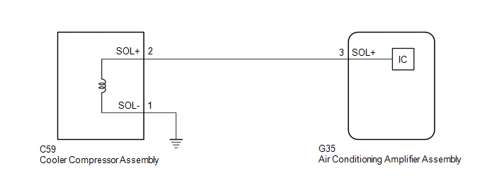
DESCRIPTION
The cooler compressor assembly receives refrigerant compression demand signals from the air conditioning amplifier assembly.
Based on this signal, the cooler compressor assembly changes the amount of compressor output.
|
DTC No. | Detection Item |
DTC Detection Condition | Trouble Area |
Memory |
|---|---|---|---|---|
| B1451 |
Compressor Solenoid Circuit |
Open or short in compressor solenoid circuit |
| - |
WIRING DIAGRAM
PROCEDURE
| 1. |
INSPECT AIR CONDITIONING AMPLIFIER ASSEMBLY |
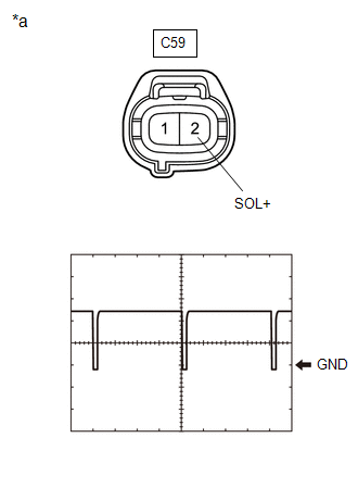
|
*a | Front view of wire harness connector (to Cooler Compressor Assembly) |
(a) Disconnect the C59 cooler compressor assembly connector.
(b) Connect an oscilloscope to terminal C59-2 (SOL+) and body ground and check the waveform.
|
Item | Content |
|---|---|
|
Tool Setting | 5 V/DIV., 500 μs./DIV. |
|
Condition |
|
OK:
Waveform is similar to that shown in the illustration.
| OK |  | REPLACE COOLER COMPRESSOR ASSEMBLY |
|
| 2. |
CHECK HARNESS AND CONNECTOR (COOLER COMPRESSOR ASSEMBLY - AIR CONDITIONING AMPLIFIER ASSEMBLY) |
(a) Disconnect the G35 air conditioning amplifier assembly connector.
(b) Measure the resistance according to the value(s) in the table below.
Standard Resistance:
|
Tester Connection | Condition |
Specified Condition |
|---|---|---|
|
C59-2 (SOL+) - G35-3 (SOL+) |
Always | Below 1 Ω |
|
C59-2 (SOL+) or G35-3 (SOL+) - Other terminals and body ground |
Always | 10 kΩ or higher |
| OK | | REPLACE AIR CONDITIONING AMPLIFIER ASSEMBLY |
| NG | | REPAIR OR REPLACE HARNESS OR CONNECTOR |
DESCRIPTION
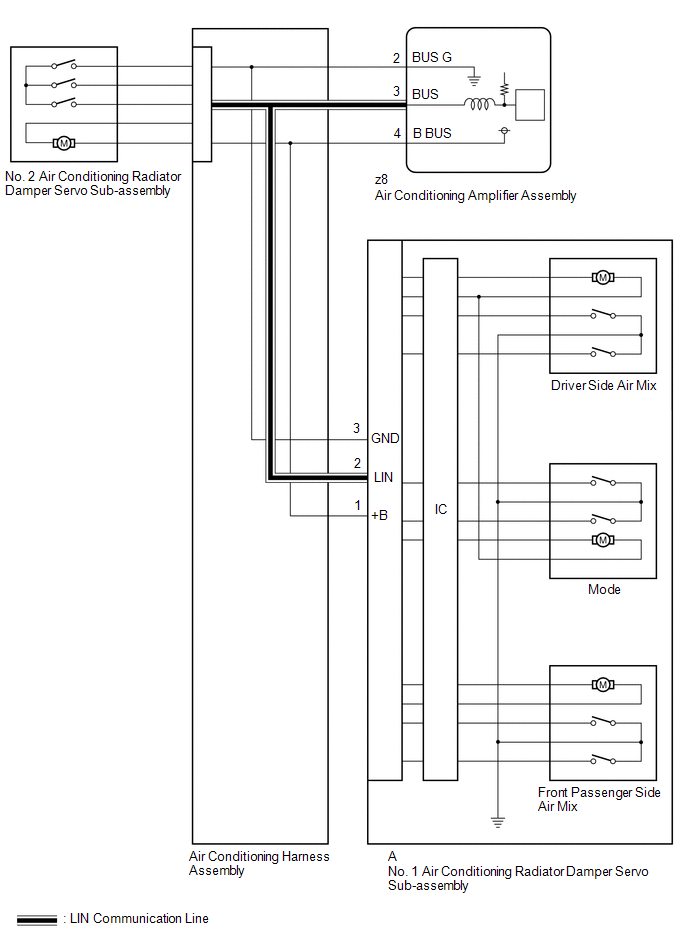
The air conditioning harness assembly connects the air conditioning amplifier assembly and the servo motors. The air conditioning amplifier assembly supplies power and sends operation instructions to each servo motor through the air conditioning harness assembly. Each servo motor sends damper position information to the air conditioning amplifier assembly.
|
DTC No. | Detection Item |
DTC Detection Condition | Trouble Area |
Memory |
|---|---|---|---|---|
| B1497 |
Communication Malfunction (Bus Ic) |
Error or open in communication line |
| Memorized (10 sec. or more)* |
WIRING DIAGRAM
PROCEDURE
| 1. |
PERFORM ACTIVE TEST USING TECHSTREAM |
(a) Connect the Techstream to the DLC3.
(b) Turn the engine switch on (IG).
(c) Turn the Techstream on.
(d) Enter the following menus: Body Electrical / Air Conditioner / Active test.
(e) Perform the Active Test according to the display on the Techstream.
Body Electrical > Air Conditioner > Active Test|
Tester Display | Measurement Item |
Control Range | Diagnostic Note |
|---|---|---|---|
|
Air Mix Servo Targ Pulse(D) |
No. 1 air conditioning radiator damper servo sub-assembly (driver side air mix) pulse |
Min.: 128 Max.: 383 |
Operates between 165 and 257 pulses |
|
A/O Servo Pulse(Rr D) | No. 2 air conditioning radiator damper servo sub-assembly pulse |
Min.: 128 Max.: 383 |
Operates between 158 and 260 pulses |
|
Tester Display |
|---|
| Air Mix Servo Targ Pulse(D) |
|
Tester Display |
|---|
| A/O Servo Pulse(Rr D) |
|
Result | Proceed to |
|---|---|
|
All of the damper servo motors are malfunctioning |
A |
| One of the damper servo motors is malfunctioning |
B |
| B |
 | GO TO STEP 4 |
|
| 2. |
PERFORM ACTIVE TEST USING TECHSTREAM |
(a) Disconnect the No. 1 air conditioning radiator damper servo sub-assembly connector.
(b) Connect the Techstream to the DLC3.
(c) Turn the engine switch on (IG).
(d) Turn the Techstream on.
(e) Enter the following menus: Body Electrical / Air Conditioner / Active test.
(f) Perform the Active Test according to the display on the Techstream.
Body Electrical > Air Conditioner > Active Test|
Tester Display | Measurement Item |
Control Range | Diagnostic Note |
|---|---|---|---|
|
A/O Servo Pulse(Rr D) | No. 2 air conditioning radiator damper servo sub-assembly pulse |
Min.: 128 Max.: 383 |
Operates between 158 and 260 pulses |
|
Tester Display |
|---|
| A/O Servo Pulse(Rr D) |
OK:
The damper servo motor operates smoothly.
| OK | | REPLACE NO. 1 AIR CONDITIONING RADIATOR DAMPER SERVO SUB-ASSEMBLY |
|
| 3. |
INSPECT AIR CONDITIONING AMPLIFIER ASSEMBLY |
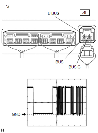
|
*a | Component with harness connected (Air Conditioning Amplifier Assembly) |
NOTICE:
When inspecting the air conditioning amplifier assembly, do not bring the tester probes too close to each other as a short circuit may occur.
(a) Disconnect the z8 air conditioning amplifier assembly connector.
(b) Measure the voltage and resistance according to the value(s) in the table below.
Standard Voltage:
|
Tester Connection | Condition |
Specified Condition |
|---|---|---|
|
z8-4 (B BUS) - Body ground |
Engine switch on (IG) |
11 to 14 V |
Standard Resistance:
|
Tester Connection | Condition |
Specified Condition |
|---|---|---|
|
z8-2 (BUS G) - Body ground |
Always | Below 1 Ω |
(c) Turn the engine switch on (IG).
(d) Using an oscilloscope, check the waveform.
|
Item | Content |
|---|---|
|
Terminal No. | z8-3 (BUS) - z8-2 (BUS G) |
|
Tool Setting | 2 V/DIV., 2 ms./DIV. |
|
Condition | Engine switch on (IG) |
OK:
Waveform is similar to that shown in the illustration.
HINT:
The waveform varies with the blower speed.
| OK | | REPLACE AIR CONDITIONING HARNESS ASSEMBLY |
| NG | | REPLACE AIR CONDITIONING AMPLIFIER ASSEMBLY |
| 4. |
PERFORM ACTIVE TEST USING TECHSTREAM |
(a) Connect the Techstream to the DLC3.
(b) Turn the engine switch on (IG).
(c) Turn the Techstream on.
(d) Enter the following menus: Body Electrical / Air Conditioner / Active test.
(e) Perform the Active Test according to the display on the Techstream.
Body Electrical > Air Conditioner > Active Test|
Tester Display | Measurement Item |
Control Range | Diagnostic Note |
|---|---|---|---|
|
Air Mix Servo Targ Pulse(D) |
No. 1 air conditioning radiator damper servo sub-assembly (driver side air mix) pulse |
Min.: 128 Max.: 383 |
Operates between 165 and 257 pulses |
|
A/O Servo Pulse(Rr D) | No. 2 air conditioning radiator damper servo sub-assembly pulse |
Min.: 128 Max.: 383 |
Operates between 158 and 260 pulses |
|
Tester Display |
|---|
| Air Mix Servo Targ Pulse(D) |
|
Tester Display |
|---|
| A/O Servo Pulse(Rr D) |
|
Result | Proceed to |
|---|---|
|
Only the No. 1 air conditioning radiator damper servo sub-assembly does not operate |
A |
| Only the No. 2 air conditioning radiator damper servo sub-assembly does not operate |
B |
| B |
| REPLACE AIR CONDITIONING HARNESS ASSEMBLY |
|
| 5. |
INSPECT AIR CONDITIONING HARNESS ASSEMBLY (AIR CONDITIONING AMPLIFIER ASSEMBLY - NO. 1 AIR CONDITIONING RADIATOR DAMPER SERVO SUB-ASSEMBLY) |
(a) Disconnect the z8 air conditioning amplifier assembly connector.
(b) Disconnect the No. 1 air conditioning radiator damper servo sub-assembly connector.
(c) Measure the resistance according to the value(s) in the table below.
Standard Resistance:
|
Tester Connection | Condition |
Specified Condition |
|---|---|---|
|
z8-2 (BUS G) - A-3 (GND) |
Always | Below 1 Ω |
|
z8-3 (BUS) - A-2 (LIN) |
Always | Below 1 Ω |
|
z8-4 (B BUS) - A-1 (+B) |
Always | Below 1 Ω |
| OK | | REPLACE NO. 1 AIR CONDITIONING RADIATOR DAMPER SERVO SUB-ASSEMBLY |
| NG | | REPLACE AIR CONDITIONING HARNESS ASSEMBLY |
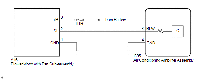
DESCRIPTION
The blower motor with fan sub-assembly is operated by signals from the air conditioning amplifier assembly. Blower motor speed signals are transmitted in accordance with changes in the duty ratio.
If the airflow volume is low or the blower speed cannot be changed, the following factors may be the cause.
|
Symptom | Factor |
|---|---|
|
Airflow volume cannot be changed |
|
WIRING DIAGRAM
CAUTION / NOTICE / HINT
NOTICE:
Inspect the fuses for circuits related to this system before performing the following procedure.
PROCEDURE
| 1. |
PERFORM ACTIVE TEST USING TECHSTREAM |
(a) Connect the Techstream to the DLC3.
(b) Turn the engine switch on (IG).
(c) Turn the Techstream on.
(d) Enter the following menus: Body Electrical / Air Conditioner / Active Test.
(e) Perform the Active Test according to the display on the Techstream.
Body Electrical > Air Conditioner > Active Test|
Tester Display | Measurement Item |
Control Range | Diagnostic Note |
|---|---|---|---|
|
Blower Motor | Blower motor with fan sub-assembly |
Min.: 0 Max.: 31 |
- |
|
Tester Display |
|---|
| Blower Motor |
| Result |
Proceed to |
|---|---|
| Blower motor with fan sub-assembly does not operate |
A |
| Blower motor with fan sub-assembly operates but does not change speed |
B |
| B |
 | GO TO STEP 5 |
|
| 2. |
CHECK HARNESS AND CONNECTOR (BLOWER MOTOR WITH FAN SUB-ASSEMBLY - POWER SOURCE AND BODY GROUND) |
(a) Disconnect the A16 blower motor with fan sub-assembly connector.
(b) Measure the voltage and resistance according to the value(s) in the table below.
Standard Voltage:
|
Tester Connection | Condition |
Specified Condition |
|---|---|---|
|
A16-3 (+B) - Body ground |
Always | 11 to 14 V |
Standard Resistance:
|
Tester Connection | Condition |
Specified Condition |
|---|---|---|
|
A16-1 (GND) - Body ground |
Always | Below 1 Ω |
| NG | | REPAIR OR REPLACE HARNESS OR CONNECTOR |
|
| 3. |
CHECK HARNESS AND CONNECTOR (BLOWER MOTOR WITH FAN SUB-ASSEMBLY - AIR CONDITIONING AMPLIFIER ASSEMBLY) |
(a) Disconnect the G35 air conditioning amplifier assembly connector.
(b) Measure the resistance according to the value(s) in the table below.
Standard Resistance:
|
Tester Connection | Condition |
Specified Condition |
|---|---|---|
|
A16-2 (SI) - G35-6 (BLW) |
Always | Below 1 Ω |
|
A16-2 (SI) or G35-6 (BLW) - Other terminals and body ground |
Always | 10 kΩ or higher |
| NG | | REPAIR OR REPLACE HARNESS OR CONNECTOR |
|
| 4. |
INSPECT BLOWER MOTOR WITH FAN SUB-ASSEMBLY |
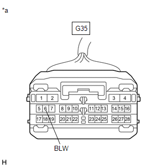
|
*a | Front view of wire harness connector (to Air Conditioning Amplifier Assembly) |
(a) Connect the A16 blower motor with fan sub-assembly connector.
(b) Measure the voltage according to the value(s) in the table below.
Standard Voltage:
|
Tester Connection | Condition |
Specified Condition |
|---|---|---|
|
G35-6 (BLW) - Body ground |
Always | 4.75 to 5.25 V |
| NG | | REPLACE BLOWER MOTOR WITH FAN SUB-ASSEMBLY |
|
| 5. |
INSPECT AIR CONDITIONING AMPLIFIER ASSEMBLY |
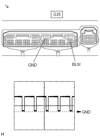
|
*a | Component with harness connected (Air Conditioning Amplifier Assembly) |
(a) Connect the G35 air conditioning amplifier assembly connector.
(b) Turn the engine switch on (IG).
(c) Set the blower speed to LO.
(d) Using an oscilloscope, check the waveform.
|
Item | Content |
|---|---|
|
Terminal No. | G35-6 (BLW) - G35-4 (GND) |
|
Tool Setting | 2 V/DIV., 1 ms./DIV. |
|
Condition |
|
OK:
Waveform is similar to that shown in the illustration.
HINT:
The waveform varies with the blower speed.
| OK | | REPLACE BLOWER MOTOR WITH FAN SUB-ASSEMBLY |
| NG | | REPLACE AIR CONDITIONING AMPLIFIER ASSEMBLY |
DESCRIPTION
If air does not flow from the front registers after the blower switch on the air conditioning control panel (radio and display receiver assembly) is operated, the following factors may be the cause.
|
Symptom | Factor |
|---|---|
|
No air flows from the registers |
|
PROCEDURE
| 1. |
CHECK AIR CONDITIONING SYSTEM (MANUAL MODE) |
(a) Turn off the AUTO switch, operate the blower switch and check that the blower motor with fan sub-assembly can be operated manually.
OK:
The blower motor with fan sub-assembly operates normally.
| NG |  | GO TO OTHER DIAGNOSIS PROCEDURE (Blower Motor Circuit) |
|
| 2. |
READ VALUE USING TECHSTREAM |
(a) Connect the Techstream to the DLC3.
(b) Turn the engine switch on (IG).
(c) Turn the Techstream on.
(d) Enter the following menus: Powertrain / Engine / Data List.
(e) Read the Data List according to the display on the Techstream.
Powertrain > Engine > Data List|
Tester Display | Measurement Item |
Range | Normal Condition |
Diagnostic Note |
|---|---|---|---|---|
|
Coolant Temperature | Engine coolant temperature |
Min.: -40°C (-40°F), Max.: 140°C (284°F) |
75 to 100°C (167 to 212°F): After warming up |
This is the engine coolant temperature. HINT:
|
|
Tester Display |
|---|
| Coolant Temperature |
OK:
After warming up the engine, the temperature value displayed is within the range specified in the normal condition column.
| OK | | REPLACE AIR CONDITIONING AMPLIFIER ASSEMBLY |
| NG | | GO TO COOLING SYSTEM |
DESCRIPTION
If the cooling effect of the air conditioning system is weak, the following factors may be the cause.
|
Symptom | Factor |
|---|---|
|
|
WIRING DIAGRAM
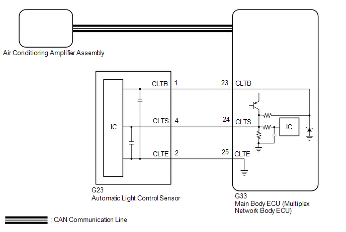
PROCEDURE
| 1. |
CHECK ECO MODE SETTING |
(a) Check if the ECO mode indicator is off.
OK:
The ECO mode indicator is off.
| OK |  | GO TO STEP 3 |
|
| 2. |
CHECK ECO MODE CONTROL OPERATION |
(a) Operate the ECO switch assembly (electric parking brake switch assembly) and check that the ECO mode indicator turns off and the blower speed reduction is canceled.
HINT:
|
Control |
Outline |
|---|---|
|
Blower Control |
When the air conditioning system is in AUTO mode, the blower speed will be reduced to a certain speed. Additionally, if warm-up control is operating, the blower speed will be further reduced. |
|
Air Inlet Control |
If the ambient temperature is a certain value or more, the air inlet mode will be changed to recirculation mode. |
|
Result | Proceed to |
|---|---|
|
ECO mode indicator turns off and blower speed reduction is canceled |
A |
| ECO mode indicator turns off, but the blower speed reduction is not canceled |
B |
| ECO mode indicator does not turn off |
| B |
| GO TO ECO Switch Circuit |
|
| 3. |
PERFORM REFRIGERANT SHORTAGE CHECK |
(a) Connect the Techstream to the DLC3.
(b) Turn the engine switch on (IG).
(c) Turn the Techstream on.
(d) Enter the following menus: Body Electrical / Air Conditioner / Utility / Refrigerant Gas Volume Check.
Body Electrical > Air Conditioner > Utility|
Tester Display |
|---|
| Refrigerant Gas Volume Check |
(e) Check that the following conditions are met and perform the refrigerant shortage check according to the display on the Techstream.
Measurement Condition:|
Item | Condition |
|---|---|
|
A/C switch | On |
|
Ambient temperature* |
0 to 49°C (32 to 120°F) |
|
Blower speed | HI |
*: If the ambient temperature is not within the range shown, do not perform this check.
|
Result | Amount of Refrigerant |
|---|---|
|
Refrigerant correct | Correct |
|
Refrigerant shortage |
Insufficient |
OK:
"Refrigerant correct" is displayed on the Techstream.
| NG | | REPAIR REFRIGERANT LEAK |
|
| 4. |
PERFORM ACTIVE TEST USING TECHSTREAM |
(a) Connect the Techstream to the DLC3.
(b) Turn the engine switch on (IG).
(c) Turn the Techstream on.
(d) Enter the following menus: Body Electrical / Air Conditioner / Active Test.
(e) Perform the Active Test according to the display on the Techstream.
Body Electrical > Air Conditioner > Active Test|
Tester Display | Measurement Item |
Control Range | Diagnostic Note |
|---|---|---|---|
|
Air Mix Servo Targ Pulse(D) |
No. 1 air conditioning radiator damper servo sub-assembly (driver side air mix) pulse |
Min.: 128 Max.: 383 |
Operates between 165 and 257 pulses |
|
Air Mix Servo Targ Pulse(P) |
No. 1 air conditioning radiator damper servo sub-assembly (front passenger side air mix) pulse |
Min.: 128 Max.: 383 |
Operates between 255 and 347 pulses |
|
Tester Display |
|---|
| Air Mix Servo Targ Pulse(D) |
|
Tester Display |
|---|
| Air Mix Servo Targ Pulse(P) |
OK:
Each damper servo motor operates.
| NG | | GO TO DTC TROUBLESHOOTING PROCEDURE FOR MALFUNCTIONING DAMPER SERVO MOTOR |
|
| 5. |
CHECK HARNESS AND CONNECTOR (AUTOMATIC LIGHT CONTROL SENSOR - MAIN BODY ECU (MULTIPLEX NETWORK BODY ECU)) |
(a) Disconnect the G23 automatic light control sensor connector.
(b) Disconnect the G33 main body ECU (multiplex network body ECU) connector.
(c) Measure the resistance according to the value(s) in the table below.
Standard Resistance:
|
Tester Connection | Condition |
Specified Condition |
|---|---|---|
|
G23-1 (CLTB) - G33-23 (CLTB) |
Always | Below 1 Ω |
|
G23-2 (CLTE) - G33-25 (CLTE) |
Always | Below 1 Ω |
|
G23-4 (CLTS) - G33-24 (CLTS) |
Always | Below 1 Ω |
|
G23-1 (CLTB) or G33-23 (CLTB) - Other terminals and body ground |
Always | 10 kΩ or higher |
|
G23-2 (CLTE) or G33-25 (CLTE) - Other terminals and body ground |
Always | 10 kΩ or higher |
|
G23-4 (CLTS) or G33-24 (CLTS) - Other terminals and body ground |
Always | 10 kΩ or higher |
| NG | | REPAIR OR REPLACE HARNESS OR CONNECTOR |
|
| 6. |
INSPECT AUTOMATIC LIGHT CONTROL SENSOR |
(a) Remove the automatic light control sensor.
Click here

(b) Inspect the automatic light control sensor.
Click here
| OK | | INSPECT REFRIGERANT PRESSURE WITH MANIFOLD GAUGE SET |
| NG | | REPLACE AUTOMATIC LIGHT CONTROL SENSOR |
CUSTOMIZE PARAMETERS
CUSTOMIZE AIR CONDITIONING SYSTEM
(a) Customizing with the Techstream.
NOTICE:
HINT:
The following items can be customized.
(1) Connect the Techstream.
(2) Turn the engine switch on (IG).
(3) Turn the Techstream on.
(4) Enter the following menus: Customize Setting / Air Conditioner.
(5) Select the setting by referring to the table below.
Air Conditioner|
Tester Display | Description |
Default | Setting |
ECU |
|---|---|---|---|---|
| Set Temperature Shift |
Function to perform control with the shifted temperature versus the displayed temperature |
Normal | 00001:-2C,00010:-1C,00100:Normal,01000:+1C,10000:+2C |
Air conditioning amplifier assembly |
|
Evaporator Control | Function to set the evaporator control to the automatic position (Automatic) to save power or to the coldest position (Manual) to dehumidify the air and to prevent the windows from fogging up |
Automatic | 0:Automatic,1:Manual |
Air conditioning amplifier assembly |
|
Compressor Mode | Function to turn the A/C on automatically by pressing the AUTO switch when the blower is on and the A/C is off |
Automatic | 0:Automatic,1:Manual |
Air conditioning amplifier assembly |
|
Air Inlet Mode | Function to change the mode automatically to recirculation air mode when turning the A/C on to cool the cabin quickly*1 |
Automatic | 0:Automatic,1:Manual |
Air conditioning amplifier assembly |
|
Foot/DEF Auto Mode | Function to change the air outlet mode to foot/defroster automatically when AUTO mode is on |
ON | 0:ON,1:OFF |
Air conditioning amplifier assembly |
|
Foot/DEF Automatic Blow Up Function |
Function to increase the blower level automatically when the defroster is on |
ON | 0:ON,1:OFF |
Air conditioning amplifier assembly |
|
Ambient Temperature Shift |
Function to display the shifted ambient temperature versus the actual ambient temperature |
Normal | 0000001:-3C,0000010:-2C,0000100:-1C,0001000:Normal,0010000:+1C,0100000:+2C,1000000:+3C |
Air conditioning amplifier assembly |
|
ECO MODE Cancel | Function to disable the operation of the ECO switch assembly when set to OFF*2 |
OFF | 0:OFF,1:ON |
Air conditioning amplifier assembly |
|
Refrigerant Shortage Check |
Function to cancel the refrigerant shortage check (check performed during normal operation) when set to ON |
ON | 0:ON,1:OFF |
Air conditioning amplifier assembly |
|
Fan speed increment control |
Function to set the speed to reach the target blower fan speed when AUTO mode is on |
Normal | 001:Slow,010:Normal,100:Fast |
Air conditioning amplifier assembly |
|
Outside Air Mode Auto Switch Function |
Function to automatically change the air inlet to FRESH mode when the engine switch is off for 60 seconds |
ON | 0:ON,1:OFF |
Air conditioning amplifier assembly |
(b) Customizing with the multi-display.
(1) Turn the engine switch on (IG).
(2) Enter the following menus: MENU / Setup / Vehicle / Vehicle Customization / Climate Settings.
(3) Select the setting by referring to the table below.
|
Display | Default |
Content | Setting |
Relevant ECU |
|---|---|---|---|---|
| Auto A/C Mode |
On | Function to turn the A/C on automatically by pressing the AUTO switch when the blower is on and the A/C is off |
On or Off | Air conditioning amplifier assembly |
DATA LIST / ACTIVE TEST
DATA LIST
NOTICE:
In the table below, the values listed under "Normal Condition" are reference values. Do not depend solely on these reference values when deciding whether a part is faulty or not.
HINT:
Using the Techstream to read the Data List allows the values or states of switches, sensors, actuators and other items to be read without removing any parts. This non-intrusive inspection can be very useful because intermittent conditions or signals may be discovered before parts or wiring is disturbed. Reading the Data List information early in troubleshooting is one way to save diagnostic time.
(a) Connect the Techstream to the DLC3.
(b) Turn the engine switch on (IG).
(c) Turn the Techstream on.
(d) Enter the following menus:
(1) for Air Conditioner: Body Electrical / Air Conditioner / Data List.
(2) for Engine: Powertrain / Engine / Data List.
(e) Read the Data List according to the display on the Techstream.
Body Electrical > Air Conditioner > Data List|
Tester Display | Measurement Item |
Range | Normal Condition |
Diagnostic Note |
|---|---|---|---|---|
|
Room Temperature Sensor |
Cooler (room temp. sensor) thermistor |
Min.: -6.50°C (20.30°F) Max.: 57.25°C (135.05°F) |
Actual cabin temperature displayed |
Cooler (room temp. sensor) thermistor circuit malfunction
|
| Ambient Temp Sensor |
Thermistor assembly | Min.: -23.30°C (-9.94°F) Max.: 65.95°C (150.71°F) |
Actual ambient temperature displayed |
Thermistor assembly circuit malfunction
|
| Adjusted Ambient Temp |
Adjusted ambient temperature |
Min.: -30.80°C (-23.44°F) Max.: 50.80°C (123.44°F) |
Adjust ambient temperature displayed |
Air conditioning amplifier assembly malfunction |
|
Evaporator Fin Thermistor |
No. 1 cooler thermistor |
Min.: -29.70°C (-21.46°F) Max.: 59.55°C (139.19°F) |
Actual evaporator temperature displayed |
No. 1 cooler thermistor circuit malfunction
|
| Evaporator Target Temp |
Evaporator target temperature |
Min.: -327.68°C (-557.82°F) Max.: 327.67°C (621.81°F) |
Evaporator target temperature displayed |
No. 1 cooler thermistor circuit malfunction
|
| Solar Sensor (D Side) |
Driver side automatic light control sensor |
Min.: 0 Max.: 255 |
Driver side automatic light control sensor value increases as brightness increases |
Driver side automatic light control sensor circuit malfunction
|
| Solar Sensor (P Side) |
Front passenger side automatic light control sensor |
Min.: 0 Max.: 255 |
Front passenger side automatic light control sensor value increases as brightness increases |
Front passenger side automatic light control sensor circuit malfunction
|
| Engine Coolant Temp |
Engine coolant temperature sensor |
Min.: 1.30°C (34.34°F) Max.: 90.55°C (194.99°F) |
Actual engine coolant temperature displayed |
|
| Blower Motor Speed Level |
Blower motor speed level |
Min.: 0 Max.: 31 |
Displayed speed level increases in range between 0 and 31 as blower motor speed increases |
Blower motor with fan sub-assembly circuit malfunction |
|
Regulator Pressure Sensor |
Air conditioner pressure sensor |
Min.: -66.2 psi (gauge) Max.: 478.0 psi (gauge) |
Actual refrigerant pressure displayed |
|
| Regulator Control Current |
Solenoid valve control current |
Min.: 0 A Max.: 0.997 A |
Value changes between 0 A and 0.997 A in accordance with solenoid valve operation |
Cooler compressor assembly circuit malfunction |
|
Air Outlet Servo Pulse (R) |
No. 2 air conditioning radiator damper servo sub-assembly target pulse |
Min.: 128 Max.: 383 |
| No. 2 air conditioning radiator damper servo sub-assembly circuit malfunction |
|
Air Outlet Servo Actual Pls(R) |
No. 2 air conditioning radiator damper servo sub-assembly actual pulse |
Min.: 128 Max.: 383 |
| No. 2 air conditioning radiator damper servo sub-assembly circuit malfunction |
|
Air Mix Servo Targ Pulse(D) |
No. 1 air conditioning radiator damper servo sub-assembly (driver side air mix or air mix) target pulse |
Min.: 128 Max.: 383 |
| No. 1 air conditioning radiator damper servo sub-assembly (driver side air mix) circuit malfunction |
|
Air Mix Servo Actual Pulse(D) |
No. 1 air conditioning radiator damper servo sub-assembly (driver side air mix or air mix) actual pulse |
Min.: 128 Max.: 383 |
| No. 1 air conditioning radiator damper servo sub-assembly (driver side air mix) circuit malfunction |
|
Air Mix Servo Targ Pulse(P) |
No. 1 air conditioning radiator damper servo sub-assembly (front passenger side air mix) target pulse |
Min.: 128 Max.: 383 |
| No. 1 air conditioning radiator damper servo sub-assembly (front passenger side air mix) circuit malfunction |
|
Air Mix Servo Actual Pulse(P) |
No. 1 air conditioning radiator damper servo sub-assembly (front passenger side air mix) actual pulse |
Min.: 128 Max.: 383 |
| No. 1 air conditioning radiator damper servo sub-assembly (front passenger side air mix) circuit malfunction |
|
Air Outlet Servo Pulse (D) |
No. 1 air conditioning radiator damper servo sub-assembly (mode) target pulse |
Min.: 128 Max.: 383 |
| No. 1 air conditioning radiator damper servo sub-assembly (mode) circuit malfunction |
|
Air Outlet Servo Actu Pulse(D) |
No. 1 air conditioning radiator damper servo sub-assembly (mode) actual pulse |
Min.: 128 Max.: 383 |
| No. 1 air conditioning radiator damper servo sub-assembly (mode) circuit malfunction |
|
Air Inlet Damper Targ Pulse |
No. 1 blower damper servo sub-assembly target pulse |
Min.: 128 Max.: 383 |
| No. 1 blower damper servo sub-assembly circuit malfunction |
|
Air Inlet Damper Actual Pulse |
No. 1 blower damper servo sub-assembly actual pulse |
Min.: 128 Max.: 383 |
| No. 1 blower damper servo sub-assembly circuit malfunction |
|
Shift Set Temperature | Shift set temperature |
2C decr, 1C decr, Normal, 1C incr or 2C incr |
Customized value displayed |
- |
| Air Inlet Mode |
Air inlet mode | Auto or Manual |
Customized value displayed |
*1 |
| Compressor Mode |
Compressor mode | Auto or Manual |
Customized value displayed |
- |
| Evaporator Control |
Evaporator control | Auto or Manual |
Customized value displayed |
- |
| ECO MODE Cancel |
ECO mode cancel | OFF or ON |
Customized value displayed |
- |
| ECO Switch |
ECO switch assembly (electric parking brake switch assembly) |
OFF or ON | OFF: ECO switch assembly (electric parking brake switch assembly) not pushed ON: ECO switch assembly (electric parking brake switch assembly) pushed and held |
ECO switch assembly (electric parking brake switch assembly) circuit malfunction |
|
Refrigerant Shortage Check |
Refrigerant shortage check |
ON or OFF | Customized value displayed |
- |
| Fan speed increment control |
Fan speed increment control |
Slow, Normal or Fast | Customized value displayed |
- |
| Foot/DEF Auto Mode |
Foot/defroster auto mode |
ON or OFF | Customized value displayed |
- |
| Foot/DEF Auto Blow Up |
Foot/defroster auto blower speed increase |
ON or OFF | Customized value displayed |
- |
| Ambient Temperature Shift |
Ambient temperature shift |
3C decr, 2C decr, 1C decr, Normal, 1C incr, 2C incr or 3C incr |
Customized value displayed |
- |
| A/C Cutoff Signal |
A/C control cutoff signal |
OFF or ON | The ECM sends the air conditioning control cutoff signal displayed |
- |
| Refrigerant Gas Type |
Refrigerant gas type |
R134a or 1234yf | Refrigerant gas type displayed |
- |
| Set Temperature (D Side) |
Driver side set temperature |
Min.: MAX COLD Max.: MAX HOT |
Driver side set temperature displayed |
- |
| Set Temperature (P Side) |
Front passenger side set temperature |
Min.: MAX COLD Max.: MAX HOT |
Front passenger side set temperature displayed |
- |
| Outside Air Mode Auto Switch Function |
Outside air mode auto switch function |
ON or OFF | Customized value displayed |
- |
| Number of Trouble Codes |
Number of trouble codes |
Min.: 0 Max.: 255 |
Number of DTCs displayed |
- |
| Refrigerant High Pressure History |
Refrigerant high pressure history |
Min.: 0 Max.: 255 |
Number of times refrigerant high pressure history stored displayed |
*2 |
Click here 
|
Tester Display | Measurement Item |
Range | Normal Condition |
Diagnostic Note |
|---|---|---|---|---|
|
Coolant Temperature | Engine coolant temperature |
Min.: -40°C (-40°F) Max.: 140°C (284°F) |
75 to 100°C (167 to 212°F): After warming up |
This is the engine coolant temperature. HINT:
|
ACTIVE TEST
HINT:
Using the Techstream to perform Active Tests allows relays, VSVs, actuators and other items to be operated without removing any parts. This non-intrusive functional inspection can be very useful because intermittent operation may be discovered before parts or wiring is disturbed. Performing Active Tests early in troubleshooting is one way to save diagnostic time. Data List information can be displayed while performing Active Tests.
(a) Connect the Techstream to the DLC3.
(b) Turn the engine switch on (IG).
(c) Turn the Techstream on.
(d) Enter the following menus: Body Electrical / Air Conditioner / Active Test.
(e) Perform the Active Test according to the display on the Techstream.
Body Electrical > Air Conditioner > Active Test|
Tester Display | Measurement Item |
Control Range | Diagnostic Note |
|---|---|---|---|
|
Blower Motor | Blower motor with fan sub-assembly |
Min.: 0 Max.: 31 |
- |
| Magnetic Clutch Relay |
Air conditioning system operation |
OFF or ON | - |
|
Defogger Relay (Rear) | Rear window defogger |
OFF or ON | - |
|
Air Mix Servo Targ Pulse(D) |
No. 1 air conditioning radiator damper servo sub-assembly (driver side air mix) pulse |
Min.: 128 Max.: 383 |
Operates between 165 and 257 pulses |
|
Air Mix Servo Targ Pulse(P) |
No. 1 air conditioning radiator damper servo sub-assembly (front passenger side air mix) pulse |
Min.: 128 Max.: 383 |
Operates between 255 and 347 pulses |
|
Air Outlet Servo Pulse (D) |
No. 1 air conditioning radiator damper servo sub-assembly (mode) pulse |
Min.: 128 Max.: 383 |
Operates between 241 and 348 pulses |
|
Air Inlet Damper Targ Pulse |
No. 1 blower damper servo sub-assembly pulse |
Min.: 128 Max.: 383 |
Operates between 220 and 256 pulses |
|
A/O Servo Pulse(Rr D) | No. 2 air conditioning radiator damper servo sub-assembly pulse |
Min.: 128 Max.: 383 |
Operates between 158 and 260 pulses |
DIAGNOSIS SYSTEM
DESCRIPTION
Air conditioning system data and Diagnostic Trouble Codes (DTCs) can be read through the Data Link Connector 3 (DLC3) of the vehicle. When the system seems to be malfunctioning, use the Techstream to check for malfunctions and perform troubleshooting.
CHECK DLC3
Check the DLC3.
Click here 
DIAGNOSTIC TROUBLE CODE CHART
Air Conditioning System (for Gasoline Model)|
DTC No. | Detection Item |
DTC Detection Condition | Link |
|---|---|---|---|
|
B1411 | Room Temperature Sensor Circuit |
Open or short in room temperature sensor circuit |
|
|
B1412 | Ambient Temperature Sensor Circuit |
Open or short in ambient temperature sensor circuit |
|
|
B1413 | Evaporator Temperature Circuit or Evaporator Fin Thermistor |
Open or short in evaporator temperature sensor circuit |
|
|
B1422 | Compressor Lock |
Open or short in A/C lock sensor circuit |
|
|
B1423 | Open in Pressure Sensor Circuit / Abnormal Refrigerant Pressure |
|
|
|
B1441 | Air Mix Damper Control Servo Motor Circuit (Passenger Side) |
Air mix damper position sensor value does not change even if air conditioning amplifier assembly operates No. 1 air conditioning radiator damper servo sub-assembly (front passenger side air mix) |
|
|
B1442 | Air Inlet Damper Control Servo Motor |
Air inlet damper position sensor value does not change even if air conditioning amplifier assembly operates No. 1 blower damper servo sub-assembly |
|
|
B1443 | Air Outlet Damper Control Servo Motor Circuit |
Air outlet damper position sensor value does not change even if air conditioning amplifier assembly operates No. 1 air conditioning radiator damper servo sub-assembly (mode) |
|
|
B1446 | Air Mix Damper Control Servo Motor Circuit (Driver Side) |
Air mix damper position sensor value does not change even if air conditioning amplifier assembly operates No. 1 air conditioning radiator damper servo sub-assembly (driver side air mix) |
|
|
B1449 | Air Outlet Damper Control Servo Motor Circuit (Rear) |
Air outlet damper position sensor value does not change even if air conditioning amplifier assembly operates No. 2 air conditioning radiator damper servo sub-assembly |
|
|
B1451 | Compressor Solenoid Circuit |
Open or short in compressor solenoid circuit |
|
|
B1497 | Communication Malfunction (Bus Ic) |
Error or open in communication line |
|
|
B14B2 | Lost Communication with Front Panel LIN |
Lost communication with air conditioning control assembly |
|
|
B14B8 | Refrigerant Shortage |
The following condition is detected in the normal operation refrigerant shortage check: Amount of refrigerant is insufficient |
|
|
B14BD | Refrigerant Overabundance Filling Malfunction |
All of the following conditions are met 2 times or more in the same trip:
|
|
|
U0100 | Lost Communication With ECM/PCM "A" |
No communication with ECM |
|
|
U0131 | Lost Communication With Power Steering Control Module |
No communication with power steering ECU (rack and pinion power steering gear assembly) |
|
|
U0142 | Lost Communication With Body Control Module "B" |
No communication with main body ECU (multiplex network body ECU) |
|
|
U0151 | Lost Communication With Restraints Control Module |
No communication with airbag ECU assembly |
|
|
U0155 | Lost Communication With Instrument Panel Cluster (IPC) Control Module |
No communication with combination meter assembly |
|
|
U0163 | Lost Communication With Navigation Control Module |
No communication with air conditioning control panel (radio and display receiver assembly) |
|
DTC CHECK / CLEAR
CHECK FOR DTC
(a) Connect the Techstream to the DLC3.
(b) Turn the engine switch on (IG).
(c) Turn the Techstream on.
(d) Enter the following menus: Body Electrical / Air Conditioner / Trouble Codes.
Body Electrical > Air Conditioner > Trouble Codes(e) Check for DTCs.
CLEAR DTC
(a) Connect the Techstream to the DLC3.
(b) Turn the engine switch on (IG).
(c) Turn the Techstream on.
(d) Enter the following menus: Body Electrical / Air Conditioner / Trouble Codes.
Body Electrical > Air Conditioner > Clear DTCs(e) Clear the DTCs.
DESCRIPTION
When the ECO switch assembly (electric parking brake switch assembly) is operated, the air conditioning amplifier assembly receives a signal and enables or disables ECO mode control of the air conditioning system.
|
Symptom | Factor |
|---|---|
|
When ECO switch assembly (electric parking brake switch assembly) is operated, blower speed does not change |
|
WIRING DIAGRAM
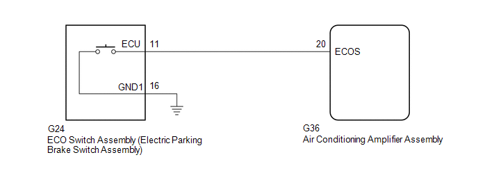
PROCEDURE
| 1. |
READ VALUE USING TECHSTREAM |
(a) Connect the Techstream to the DLC3.
(b) Turn the engine switch on (IG).
(c) Turn the Techstream on.
(d) Enter the following menus: Body Electrical / Air Conditioner / Data List.
(e) Read the Data List according to the display on the Techstream.
Body Electrical > Air Conditioner > Data List|
Tester Display | Measurement Item |
Range | Normal Condition |
Diagnostic Note |
|---|---|---|---|---|
|
ECO Switch | ECO switch assembly (electric parking brake switch assembly) |
OFF or ON | OFF: ECO switch assembly (electric parking brake switch assembly) not pushed ON: ECO switch assembly (electric parking brake switch assembly) pushed and held |
ECO switch assembly (electric parking brake switch assembly) circuit malfunction |
|
Tester Display |
|---|
| ECO Switch |
OK:
ECO switch assembly (electric parking brake switch assembly) condition displayed on the Techstream changes with the actual switch operation.
| OK |  | REPLACE AIR CONDITIONING AMPLIFIER ASSEMBLY |
|
| 2. |
INSPECT ECO SWITCH ASSEMBLY (ELECTRIC PARKING BRAKE SWITCH ASSEMBLY) |
(a) Remove the ECO switch assembly (electric parking brake switch assembly).
Click here 
(b) Inspect the ECO switch assembly (electric parking brake switch assembly).
Click here
| NG | | REPLACE ECO SWITCH ASSEMBLY (ELECTRIC PARKING BRAKE SWITCH ASSEMBLY) |
|
| 3. |
CHECK HARNESS AND CONNECTOR (ECO SWITCH ASSEMBLY (ELECTRIC PARKING BRAKE SWITCH ASSEMBLY) - AIR CONDITIONING AMPLIFIER ASSEMBLY) |
(a) Disconnect the G36 air conditioning amplifier assembly connector.
(b) Measure the resistance according to the value(s) in the table below.
Standard Resistance:
|
Tester Connection | Condition |
Specified Condition |
|---|---|---|
|
G24-11 (ECU) - G36-20 (ECOS) |
Always | Below 1 Ω |
|
G24-16 (GND1) - Body ground |
Always | Below 1 Ω |
|
G24-11 (ECU) or G36-20 (ECOS) - Other terminals and body ground |
Always | 10 kΩ or higher |
| OK | | REPLACE AIR CONDITIONING AMPLIFIER ASSEMBLY |
| NG | | REPAIR OR REPLACE HARNESS OR CONNECTOR |
DESCRIPTION
If the windshield frequently fogs up even though the air conditioning system is operating, the following factors may be the cause.
|
Symptom | Factor |
|---|---|
|
Windshield frequently fogs up |
|
PROCEDURE
| 1. |
PERFORM REFRIGERANT SHORTAGE CHECK |
(a) Connect the Techstream to the DLC3.
(b) Turn the engine switch on (IG).
(c) Turn the Techstream on.
(d) Enter the following menus: Body Electrical / Air Conditioner / Utility / Refrigerant Gas Volume Check.
Body Electrical > Air Conditioner > Utility|
Tester Display |
|---|
| Refrigerant Gas Volume Check |
(e) Check that the following conditions are met and perform the refrigerant shortage check according to the display on the Techstream.
Measurement Condition:|
Item | Condition |
|---|---|
|
A/C switch | On |
|
Ambient temperature* |
0 to 49°C (32 to 120°F) |
|
Blower speed | HI |
*: If the ambient temperature is not within the range shown, do not perform this check.
|
Result | Amount of Refrigerant |
|---|---|
|
Refrigerant correct | Correct |
|
Refrigerant shortage |
Insufficient |
OK:
"Refrigerant correct" is displayed on the Techstream.
| NG |  | CHARGE SYSTEM WITH REFRIGERANT |
|
| 2. |
CHECK OPERATION |
(a) Press the front defroster switch on the air conditioning control panel (radio and display receiver assembly).
OK:
The air outlet mode changes to DEF mode.
| OK | | INSPECT REFRIGERANT PRESSURE WITH MANIFOLD GAUGE SET |
| NG | | GO TO DTC B1443 |
CAUTION / NOTICE / HINT
HINT:
PROCEDURE
|
1. | VEHICLE BROUGHT TO WORKSHOP |
|
| 2. |
CUSTOMER PROBLEM ANALYSIS |
HINT:
|
What |
Vehicle model, system name |
|
When |
Date, time, occurrence frequency |
|
Where |
Road conditions |
|
Under what conditions? |
Driving conditions, weather conditions |
|
How did it happen? |
Problem symptoms |
|
| 3. |
INSPECT BATTERY VOLTAGE |
(a) Inspect the battery voltage.
Standard Voltage:
11 to 14 V
If the voltage is below 11 V, recharge or replace the battery before proceeding to the next step.
(b) Check the fuses and relays.
(c) Check the connector connections and terminals to make sure that there are no abnormalities such as loose connections, deformation, etc.
|
| 4. |
CHECK COMMUNICATION FUNCTION OF CAN COMMUNICATION SYSTEM* |
(a) Using the Techstream, check for CAN communication system DTCs.
Click here

|
Result | Proceed to |
|---|---|
|
CAN communication system DTCs are not output |
A |
| CAN communication system DTCs are output |
B |
| B |
 | GO TO CAN COMMUNICATION SYSTEM |
|
| 5. |
CHECK FOR DTC* |
(a) Check for DTCs and note any codes that are output.
Body Electrical > Air Conditioner > Trouble Codes(b) Clear the DTCs.
Body Electrical > Air Conditioner > Clear DTCs(c) Recheck for DTCs. Based on the DTCs output above, try to force output of the air conditioning system DTC by simulating the operation indicated by the DTC.
Body Electrical > Air Conditioner > Trouble Codes|
Result | Proceed to |
|---|---|
|
DTCs are not output | A |
|
DTCs are output | B |
| B |
| GO TO DIAGNOSTIC TROUBLE CODE CHART |
|
| 6. |
CHECK AIR CONDITIONING CONTROL PANEL (RADIO AND DISPLAY RECEIVER ASSEMBLY) |
(a) Operate each switch on the air conditioning control panel (radio and display receiver assembly) and check that the switches of the air conditioning system operate normally.
| NG | | GO TO PROBLEM SYMPTOMS TABLE |
|
| 7. |
CHECK BLOWER CONTROL |
(a) Operate the blower switch on the air conditioning control panel (radio and display receiver assembly) and check that the blower control operates normally.
| NG | | GO TO PROBLEM SYMPTOMS TABLE |
|
| 8. |
CHECK AIR INLET CONTROL |
(a) Operate the recirculation/fresh switch on the air conditioning control panel (radio and display receiver assembly) and check that the air inlet control operates normally.
| NG | |
GO TO PROBLEM SYMPTOMS TABLE |
|
| 9. |
CHECK AIR OUTLET CONTROL |
(a) Operate the air outlet mode switch on the air conditioning control panel (radio and display receiver assembly) and check that the air outlet control operates normally.
| NG | |
GO TO PROBLEM SYMPTOMS TABLE |
|
| 10. |
CHECK COOLING FUNCTION |
(a) Operate the temperature adjustment switches on the air conditioning control panel (radio and display receiver assembly) and check that cool air is blown from the registers.
| NG | |
GO TO PROBLEM SYMPTOMS TABLE |
|
| 11. |
CHECK HEATER FUNCTION |
(a) Operate the temperature adjustment switches on the air conditioning control panel (radio and display receiver assembly) and check that warm air is blown from the registers.
| NG | |
GO TO PROBLEM SYMPTOMS TABLE |
|
| 12. |
USE SIMULATION METHOD TO CHECK |
Click here
|
| 13. |
CONFIRMATION TEST |
| NEXT | | END |
INITIALIZATION
SERVO MOTOR INITIALIZATION
(a) Connect the Techstream to the DLC3.
(b) Turn the engine switch on (IG).
(c) Press the OFF switch.
(d) Turn the Techstream on.
(e) Enter the following menus: Body Electrical / Air Conditioner / Utility / Servomotor Initialization.
(f) According to the Techstream display, perform servo motor initialization.
Body Electrical > Air Conditioner > Utility|
Tester Display |
|---|
| Servomotor Initialization |
HINT:
When initialization is started, the AUTO switch indicator will illuminate and then will turn off when initialization has completed.
(g) Select Exit to complete initialization.
DESCRIPTION
If warm air blows from the registers regardless of the temperature setting of the air conditioning system, the following factors may be the cause.
|
Symptom | Factor |
|---|---|
|
No cool air comes out
|
|
PROCEDURE
| 1. |
CHECK SWITCH INDICATOR |
(a) Operate each switch on the air conditioning control panel (radio and display receiver assembly) and check that the switch indicators operate normally.
OK:
All switch indicators operate normally.
| NG |  | GO TO OTHER DIAGNOSIS PROCEDURE (Operation not Accepted Even If Air Conditioning Switch is Operated) |
|
| 2. |
PERFORM ACTIVE TEST USING TECHSTREAM |
(a) Connect the Techstream to the DLC3.
(b) Turn the engine switch on (IG).
(c) Turn the Techstream on.
(d) Enter the following menus: Body Electrical / Air Conditioner / Active Test.
(e) Perform the Active Test according to the display on the Techstream.
Body Electrical > Air Conditioner > Active Test|
Tester Display | Measurement Item |
Control Range | Diagnostic Note |
|---|---|---|---|
|
Air Mix Servo Targ Pulse(D) |
No. 1 air conditioning radiator damper servo sub-assembly (driver side air mix) pulse |
Min.: 128 Max.: 383 |
Operates between 165 and 257 pulses |
|
Air Mix Servo Targ Pulse(P) |
No. 1 air conditioning radiator damper servo sub-assembly (front passenger side air mix) pulse |
Min.: 128 Max.: 383 |
Operates between 255 and 347 pulses |
|
Tester Display |
|---|
| Air Mix Servo Targ Pulse(D) |
|
Tester Display |
|---|
| Air Mix Servo Targ Pulse(P) |
OK:
Each damper servo motor operates.
| OK | | INSPECT REFRIGERANT PRESSURE WITH MANIFOLD GAUGE SET |
| NG | | GO TO DTC TROUBLESHOOTING PROCEDURE FOR MALFUNCTIONING DAMPER SERVO MOTOR |
DESCRIPTION
If cool air blows from the registers regardless of the temperature setting of the air conditioning system, the following factors may be the cause.
|
Symptom | Factor |
|---|---|
|
|
PROCEDURE
| 1. |
READ VALUE USING TECHSTREAM |
(a) Connect the Techstream to the DLC3.
(b) Turn the engine switch on (IG).
(c) Turn the Techstream on.
(d) Enter the following menus: Powertrain / Engine / Data List.
(e) Read the Data List according to the display on the Techstream.
Powertrain > Engine > Data List|
Tester Display | Measurement Item |
Range | Normal Condition |
Diagnostic Note |
|---|---|---|---|---|
|
Coolant Temperature | Engine coolant temperature |
Min.: -40°C (-40°F), Max.: 140°C (284°F) |
75 to 100°C (167 to 212°F): After warming up |
This is the engine coolant temperature. HINT:
|
|
Tester Display |
|---|
| Coolant Temperature |
OK:
After warming up the engine, the temperature value displayed is within the range specified in the normal condition column.
| NG |  | GO TO COOLING SYSTEM |
|
| 2. |
PERFORM ACTIVE TEST USING TECHSTREAM |
(a) Connect the Techstream to the DLC3.
(b) Turn the engine switch on (IG).
(c) Turn the Techstream on.
(d) Enter the following menus: Body Electrical / Air Conditioner / Active Test.
(e) Perform the Active Test according to the display on the Techstream.
Body Electrical > Air Conditioner > Active Test|
Tester Display | Measurement Item |
Control Range | Diagnostic Note |
|---|---|---|---|
|
Air Mix Servo Targ Pulse(D) |
No. 1 air conditioning radiator damper servo sub-assembly (driver side air mix) pulse |
Min.: 128 Max.: 383 |
Operates between 165 and 257 pulses |
|
Air Mix Servo Targ Pulse(P) |
No. 1 air conditioning radiator damper servo sub-assembly (front passenger side air mix) pulse |
Min.: 128 Max.: 383 |
Operates between 255 and 347 pulses |
|
Tester Display |
|---|
| Air Mix Servo Targ Pulse(D) |
|
Tester Display |
|---|
| Air Mix Servo Targ Pulse(P) |
OK:
Each damper servo motor operates.
| OK | | REPLACE HEATER RADIATOR UNIT SUB-ASSEMBLY |
| NG | | GO TO DTC TROUBLESHOOTING PROCEDURE FOR MALFUNCTIONING DAMPER SERVO MOTOR |
DESCRIPTION
If the air conditioning system cannot be operated using the air conditioning control panel (radio and display receiver assembly), the following factors may be the cause.
|
Symptom | Factor |
|---|---|
|
Air conditioning system cannot be operated using air conditioning control panel (radio and display receiver assembly)
|
|
WIRING DIAGRAM
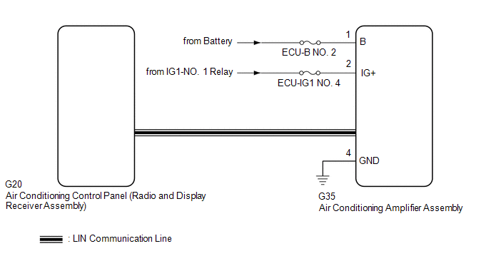
CAUTION / NOTICE / HINT
NOTICE:
Inspect the fuses for circuits related to this system before performing the following procedure.
PROCEDURE
| 1. |
CHECK FOR DTC |
(a) Check for DTCs.
Body Electrical > Air Conditioner > Trouble Codes|
Result | Proceed to |
|---|---|
|
B14B2 is not output | A |
|
B14B2 is output | B |
| B |
 | GO TO DTC B14B2 |
|
| 2. |
CHECK HARNESS AND CONNECTOR (AIR CONDITIONING AMPLIFIER ASSEMBLY - BATTERY AND BODY GROUND) |
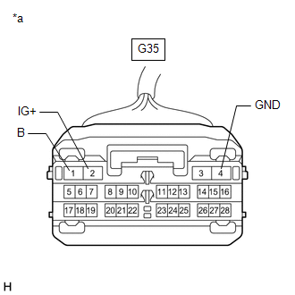
|
*a | Front view of wire harness connector (to Air Conditioning Amplifier Assembly) |
(a) Disconnect the G35 air conditioning amplifier assembly connector.
(b) Measure the voltage and resistance according to the value(s) in the table below.
Standard Voltage:
|
Tester Connection | Switch Condition |
Specified Condition |
|---|---|---|
|
G35-1 (B) - Body ground |
Always | 11 to 14 V |
|
G35-2 (IG+) - Body ground |
Engine switch on (IG) |
11 to 14 V |
|
Engine switch off | Below 1 V |
Standard Resistance:
|
Tester Connection | Condition |
Specified Condition |
|---|---|---|
|
G35-4 (GND) - Body ground |
Always | Below 1 Ω |
| OK | | REPLACE AIR CONDITIONING AMPLIFIER ASSEMBLY |
| NG | | REPAIR OR REPLACE HARNESS OR CONNECTOR |
PARTS LOCATION
ILLUSTRATION
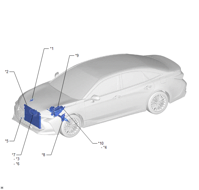
|
*1 | AIR CONDITIONER PRESSURE SENSOR |
*2 | COOLER CONDENSER ASSEMBLY |
|
*3 | MAGNET CLUTCH ASSEMBLY |
*4 | MG CLT RELAY |
|
*5 | THERMISTOR ASSEMBLY |
*6 | COOLER COMPRESSOR ASSEMBLY |
|
*7 | COMPRESSOR ASSEMBLY WITH MAGNETIC CLUTCH |
*8 | POWER STEERING ECU (RACK AND PINION POWER STEERING GEAR ASSEMBLY) |
|
*9 | ECM |
*10 | NO. 1 ENGINE ROOM RELAY BLOCK AND NO. 1 JUNCTION BLOCK ASSEMBLY - HTR FUSE - A/C COMP FUSE |
ILLUSTRATION
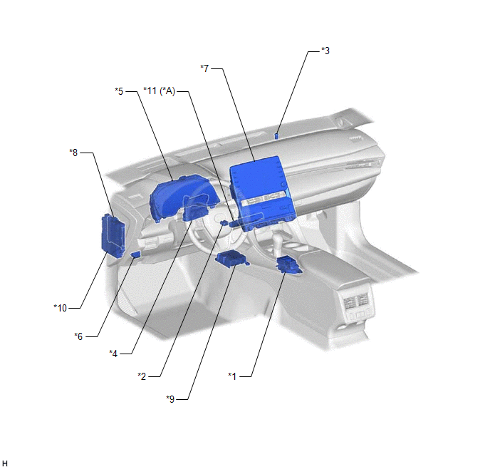
|
*A | w/ Manual (SOS) Switch |
- | - |
|
*1 | ECO SWITCH ASSEMBLY (ELECTRIC PARKING BRAKE SWITCH ASSEMBLY) |
*2 | COOLER (ROOM TEMP. SENSOR) THERMISTOR |
|
*3 | AUTOMATIC LIGHT CONTROL SENSOR |
*4 | AIR CONDITIONING AMPLIFIER ASSEMBLY |
|
*5 | COMBINATION METER ASSEMBLY |
*6 | DLC3 |
|
*7 | AIR CONDITIONING CONTROL PANEL (RADIO AND DISPLAY RECEIVER ASSEMBLY) |
*8 | MAIN BODY ECU (MULTIPLEX NETWORK BODY ECU) |
|
*9 | AIRBAG ECU ASSEMBLY |
*10 | INSTRUMENT PANEL JUNCTION BLOCK ASSEMBLY - ECU-B NO. 2 FUSE - ECU-IG1 NO. 3 FUSE - ECU-IG1 NO. 4 FUSE - ECU-ACC FUSE |
|
*11 | DCM (TELEMATICS TRANSCEIVER) |
- | - |
ILLUSTRATION
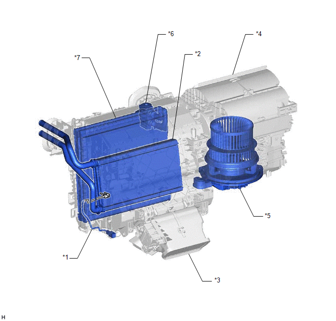
|
*1 | NO. 1 COOLER THERMISTOR |
*2 | HEATER RADIATOR UNIT SUB-ASSEMBLY |
|
*3 | AIR CONDITIONING RADIATOR ASSEMBLY |
*4 | BLOWER ASSEMBLY |
|
*5 | BLOWER MOTOR WITH FAN SUB-ASSEMBLY |
*6 | COOLER EXPANSION VALVE |
|
*7 | NO. 1 COOLER EVAPORATOR SUB-ASSEMBLY |
- | - |
ILLUSTRATION
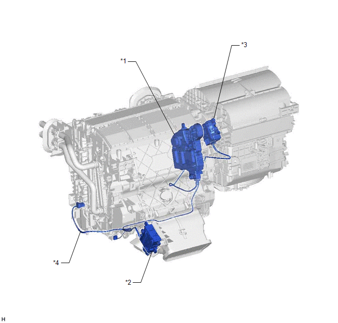
|
*1 | NO. 1 AIR CONDITIONING RADIATOR DAMPER SERVO SUB-ASSEMBLY |
*2 | NO. 2 AIR CONDITIONING RADIATOR DAMPER SERVO SUB-ASSEMBLY |
|
*3 | NO. 1 BLOWER DAMPER SERVO SUB-ASSEMBLY |
*4 | AIR CONDITIONING HARNESS ASSEMBLY |
PRECAUTION
PRECAUTION FOR DISCONNECTING CABLE FROM NEGATIVE BATTERY TERMINAL
NOTICE:
When disconnecting the cable from the negative (-) battery terminal, initialize the following systems after the cable is reconnected.
|
System Name | See Procedure |
|---|---|
|
Lane Departure Alert System (w/ Steering Control) |
|
|
Intelligent Clearance Sonar System | |
|
Parking Assist Monitor System | |
|
Panoramic View Monitor System | |
|
Pre-collision System | |
|
Lighting System (for Gasoline Model with Cornering Light) |
DO NOT HANDLE REFRIGERANT IN AN ENCLOSED AREA OR NEAR AN OPEN FLAME
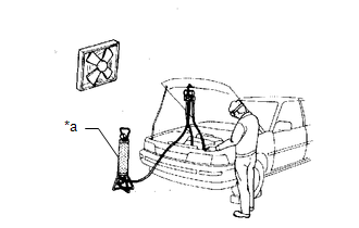
|
*a | Charging Cylinder |
ALWAYS WEAR EYE PROTECTION
BE CAREFUL NOT TO GET LIQUID REFRIGERANT IN YOUR EYES OR ON YOUR SKIN
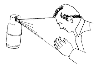
If liquid refrigerant gets in your eyes or on your skin.
(a) Wash the area with lots of cold water.
CAUTION:
Do not rub your eyes or skin.
(b) Apply clean petroleum jelly to the skin.
(c) Go immediately to a hospital or see a physician for professional treatment.
NEVER HEAT CONTAINER OR EXPOSE CONTAINER TO AN OPEN FLAME
BE CAREFUL NOT TO DROP CONTAINER OR APPLY PHYSICAL SHOCKS TO IT
DO NOT OPERATE COMPRESSOR WITHOUT ENOUGH REFRIGERANT IN REFRIGERANT SYSTEM
If there is not enough refrigerant in the air conditioning system, oil lubrication will be insufficient and the compressor may be damaged.
Necessary care should be taken to avoid this.
DO NOT OPEN HIGH PRESSURE MANIFOLD VALVE WHILE COMPRESSOR IS OPERATING
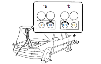
|
*a | Wrong |
|
*b | Okay |
Open and close only the low pressure valve.
If the high pressure valve is opened, refrigerant will flow in the reverse direction causing the charging cylinder to rupture.
BE CAREFUL NOT TO OVERCHARGE SYSTEM WITH REFRIGERANT
If the system is overcharged with refrigerant, it causes problems such as insufficient cooling, poor fuel economy, engine overheating, etc.
DO NOT OPERATE ENGINE AND COMPRESSOR WITH NO REFRIGERANT
CAUTION:
Doing so may damage the inside of the compressor because the compressor parts always move regardless of whether the air conditioning system is turned on or off.
SUPPLEMENTAL RESTRAINT SYSTEM (SRS)
This vehicle is equipped with a Supplemental Restraint System (SRS). Failure to carry out service operations in the correct sequence could cause the SRS to unexpectedly deploy during servicing, possibly leading to a serious accident. Before servicing (including removal or installation of parts, inspection or replacement), be sure to read the precautionary notices.
Click here 
GENERAL PRECAUTION
While using the battery during inspection, do not bring the positive (+) and negative (-) tester probes too close to each other as a short circuit may occur.
PROBLEM SYMPTOMS TABLE
HINT:
VEHICLE CHECK ITEMS
HINT:
Malfunction Operation/Function:
|
Common Function of Cool and Heater Function |
Only Cool Air Function |
Only Heater Function |
Suspected Area | |||
|---|---|---|---|---|---|---|
|
A/C Switch Operation |
Blower Operation | Recirculation/Fresh Function |
Air Outlet Changing Function | |||
|
x | o |
o | o |
x | x |
Go to "Problem Symptoms Table: Air Conditioning Control" |
|
o | o |
o | o |
x | o |
Go to "Problem Symptoms Table: Cooling Function" |
|
o | o |
o | o |
o | x |
Go to "Problem Symptoms Table: Heater Function" |
|
o | x |
o | o |
x | x |
Go to "Problem Symptoms Table: Blower Control" |
|
o | o |
x | o |
x | x |
Go to "Problem Symptoms Table: Air Inlet Control" |
|
o | o |
o | x |
x | x |
Go to "Problem Symptoms Table: Air Outlet Control" |
|
x | x |
x | x |
x | x |
Air Conditioning Amplifier Assembly or Air Conditioning Assembly is Defective |
AIR CONDITIONING CONTROL
|
Symptom | Suspected Area |
Link |
|---|---|---|
| Air conditioning system cannot be operated using air conditioning control panel (radio and display receiver assembly)
|
|
|
|
Air conditioning system cannot be operated using air conditioning control panel (radio and display receiver assembly)
| Air conditioning control panel (radio and display receiver assembly) |
|
|
Air conditioning system cannot be operated using air conditioning control panel (radio and display receiver assembly) immediately after starting the engine
| Refer to "INITIALIZATION" |
|
|
A/C switch indicator does not illuminate |
|
|
COOLING FUNCTION
|
Symptom | Suspected Area |
Link |
|---|---|---|
| No cool air comes out
|
|
|
|
|
|
|
Temperature of outlet air is cooler on left or right side
|
|
|
|
|
|
HEATER FUNCTION
|
Symptom | Suspected Area |
Link |
|---|---|---|
|
|
|
|
Temperature of outlet air is warmer on left or right side
|
|
|
BLOWER CONTROL
|
Symptom | Suspected Area |
Link |
|---|---|---|
| Blower motor does not operate at all
|
|
|
|
Airflow volume cannot be changed |
|
|
|
|
|
AIR INLET CONTROL
|
Symptom | Suspected Area |
Link |
|---|---|---|
|
|
|
|
|
|
AIR OUTLET CONTROL
|
Symptom | Suspected Area |
Link |
|---|---|---|
| Air outlet mode cannot be changed
|
|
|
|
Air outlet mode cannot be changed
| Air conditioning control panel (radio and display receiver assembly) |
|
DEFROSTER CONTROL
|
Symptom | Suspected Area |
Link |
|---|---|---|
| Windshield frequently fogs up |
|
|
DESCRIPTION
If the air inlet mode cannot be changed between recirculation/fresh or exhaust gas odors can be smelled even though recirculation mode is selected, the following factors may be the cause.
|
Symptom | Factor |
|---|---|
|
|
PROCEDURE
| 1. |
CHECK NO. 1 BLOWER DAMPER SERVO SUB-ASSEMBLY |
(a) Check that the No. 1 blower damper servo sub-assembly is installed correctly.
OK:
The No. 1 blower damper servo sub-assembly is installed correctly.
| NG |  | INSTALL NO. 1 BLOWER DAMPER SERVO SUB-ASSEMBLY CORRECTLY |
|
| 2. |
CHECK FOR DTC |
(a) Check for DTCs.
Body Electrical > Air Conditioner > Trouble Codes|
Result | Proceed to |
|---|---|
|
B1442 is not output | A |
|
B1442 is output | B |
| B |
| GO TO DTC B1442 |
|
| 3. |
READ VALUE USING TECHSTREAM |
(a) Connect the Techstream to the DLC3.
(b) Turn the engine switch on (IG).
(c) Turn the Techstream on.
(d) Enter the following menus: Powertrain / Engine / Data List.
(e) Read the Data List according to the display on the Techstream.
Powertrain > Engine > Data List|
Tester Display | Measurement Item |
Range | Normal Condition |
Diagnostic Note |
|---|---|---|---|---|
|
Coolant Temperature | Engine coolant temperature |
Min.: -40°C (-40°F), Max.: 140°C (284°F) |
75 to 100°C (167 to 212°F): After warming up |
This is the engine coolant temperature. HINT:
|
|
Tester Display |
|---|
| Coolant Temperature |
OK:
After warming up the engine, the temperature value displayed is within the range specified in the normal condition column.
| OK | | REPLACE AIR CONDITIONER UNIT ASSEMBLY |
| NG | | GO TO COOLING SYSTEM |
DESCRIPTION
If recirculation/fresh mode changes unintentionally and without permission, the following causes are possible.
|
Symptom | Factor |
|---|---|
|
|
PROCEDURE
|
1. | CONFIRM MODEL |
| Result |
Proceed to |
|---|---|
| for USA and Canada |
A |
| except USA and Canada |
B |
| A |
 | GO TO STEP 3 |
|
| 2. |
CHECK CUSTOMIZE SETTING |
(a) Using the Techstream, check that the customize setting Air Inlet Mode is not set to "Automatic".
Air Conditioner|
Tester Display | Description |
Default | Setting |
ECU |
|---|---|---|---|---|
| Air Inlet Mode |
Function to change the mode automatically to recirculation air mode when turning the A/C on to cool the cabin quickly |
Automatic | 0:Automatic,1:Manual |
Air conditioning amplifier assembly |
OK:
Air Inlet Mode is not set to "Automatic".
| NG | | CUSTOMIZE SETTING |
|
| 3. |
READ VALUE USING TECHSTREAM |
(a) Connect the Techstream to the DLC3.
(b) Turn the engine switch on (IG).
(c) Turn the Techstream on.
(d) Enter the following menus: Body Electrical / Air Conditioner / Data List.
(e) Read the Data List according to the display on the Techstream.
Body Electrical > Air Conditioner > Data List|
Tester Display | Measurement Item |
Range | Normal Condition |
Diagnostic Note |
|---|---|---|---|---|
|
Ambient Temp Sensor | Thermistor assembly |
Min.: -23.30°C (-9.94°F) Max.: 65.95°C (150.71°F) |
Actual ambient temperature displayed |
Thermistor assembly circuit malfunction
|
|
Tester Display |
|---|
| Ambient Temp Sensor |
OK:
The value of the display does not change frequently.
| NG | | GO TO AMBIENT TEMPERATURE DISPLAY SYSTEM |
|
| 4. |
READ VALUE USING TECHSTREAM |
(a) Connect the Techstream to the DLC3.
(b) Turn the engine switch on (IG).
(c) Turn the Techstream on.
(d) Enter the following menus: Powertrain / Engine / Data List.
(e) Read the Data List according to the display on the Techstream.
Powertrain > Engine > Data List|
Tester Display | Measurement Item |
Range | Normal Condition |
Diagnostic Note |
|---|---|---|---|---|
|
Coolant Temperature | Engine coolant temperature |
Min.: -40°C (-40°F), Max.: 140°C (284°F) |
75 to 100°C (167 to 212°F): After warming up |
This is the engine coolant temperature. HINT:
|
|
Tester Display |
|---|
| Coolant Temperature |
OK:
The value of the display does not change frequently.
| NG | | GO TO COOLING SYSTEM |
|
| 5. |
CHECK REFRIGERANT PRESSURE |
(a) Connect the Techstream to the DLC3.
(b) Turn the engine switch on (IG).
(c) Turn the Techstream on.
(d) Enter the following menus: Body Electrical / Air Conditioner / Data List.
(e) Read the Data List according to the display on the Techstream.
Body Electrical > Air Conditioner > Data List|
Tester Display | Measurement Item |
Range | Normal Condition |
Diagnostic Note |
|---|---|---|---|---|
|
Regulator Pressure Sensor |
Air conditioner pressure sensor |
Min.: -66.2 psi (gauge) Max.: 478.0 psi (gauge) |
Actual refrigerant pressure displayed |
|
|
Tester Display |
|---|
| Regulator Pressure Sensor |
(f) Install a manifold gauge set.
(g) Read the manifold gauge pressure when the following conditions are met.
(1) Prepare the vehicle according to the table below.
Measurement Condition:|
Item | Condition |
|---|---|
|
Vehicle doors | Fully open |
|
Temperature setting | MAX COLD |
|
Blower speed | HI |
|
A/C switch | On |
|
Recirculation/fresh switch |
RECIRCULATION |
|
Interior temperature |
25 to 35°C (77 to 95°F) |
Standard Pressure:
Low pressure side
150 to 250 kPa (1.5 to 2.5 kgf/cm2, 22 to 36 psi)
High pressure side
1370 to 1570 kPa (14 to 16 kgf/cm2, 199 to 228 psi)
(h) Compare the values displayed in the Data List and on the manifold gauge.
OK:
The values displayed in the Data List and on the manifold gauge match.
| OK | | GO TO ON-VEHICLE INSPECTION (CHECK REFRIGERANT PRESSURE USING GAUGE) |
| NG | | REPLACE AIR CONDITIONER PRESSURE SENSOR |
SYSTEM DESCRIPTION
COMMUNICATION SYSTEM FUNCTION
(a) The air conditioning amplifier assembly communicates with each ECU via CAN communication and LIN communication. Additionally, the air conditioning amplifier assembly sends operation signals to each damper servo motor and receives damper position information and sensor information from the damper servo motors and No. 1 cooler thermistor through the air conditioning harness assembly.
Air Conditioning Amplifier Assembly ←→ Airbag ECU Assembly|
Receiver | Sender |
Signal | Communication Line |
|---|---|---|---|
|
Air conditioning amplifier assembly |
Airbag ECU assembly | Front passenger seat belt buckle switch status signal |
CAN |
| Front passenger seat occupant status signal |
|
Receiver | Sender |
Signal | Communication Line |
|---|---|---|---|
|
Air conditioning amplifier assembly |
Main body ECU (multiplex network body ECU) |
Auto dimmer signal |
CAN |
| Front passenger door courtesy switch signal | |||
|
Rear right door courtesy switch signal | |||
|
Rear left door courtesy switch signal | |||
|
High beam headlight request signal | |||
|
Low beam headlight request signal | |||
|
Destination symbol signal | |||
|
Country code 1st signal | |||
|
Country code 2nd signal | |||
|
Country code 3rd signal | |||
|
Steering wheel signal | |||
|
Solar data (R) signal | |||
|
Solar data (L) signal | |||
|
Main body ECU (multiplex network body ECU) |
Air conditioning amplifier assembly |
Rear defogger drive request signal |
CAN |
| Ambient temperature display signal |
|
Receiver | Sender |
Signal | Communication Line |
|---|---|---|---|
|
Air conditioning amplifier assembly |
Power steering ECU (rack and pinion power steering gear assembly) |
Loading control level signal |
CAN |
| Power steering ECU (rack and pinion power steering gear assembly) |
Air conditioning amplifier assembly |
Ambient temperature display signal |
CAN |
|
Receiver | Sender |
Signal | Communication Line |
|---|---|---|---|
|
Air conditioning amplifier assembly |
Combination meter assembly |
Vehicle speed signal (meter to other) |
CAN |
| Temperature unit signal (centigrade/fahrenheit) | |||
|
Combination meter assembly |
Air conditioning amplifier assembly |
Ambient temperature display signal |
CAN |
| Ambient temperature display whole number/decimal (0/0.5°C) signal |
|
Receiver | Sender |
Signal | Communication Line |
|---|---|---|---|
|
Air conditioning amplifier assembly |
Air conditioning control panel (radio and display receiver assembly) |
AUTO switch state signal |
CAN |
| Rear defogger switch state signal | |||
|
Air outlet switch state signal | |||
|
OFF switch state signal | |||
|
A/C switch state signal | |||
|
SYNC switch state signal | |||
|
Mode switch state signal | |||
|
Blower up switch state signal | |||
|
Blower down switch state signal | |||
|
Driver side TEMP up switch state signal | |||
|
Driver side TEMP down switch state signal | |||
|
Front passenger side TEMP up switch state signal | |||
|
Front passenger side TEMP down switch state signal | |||
|
Blower level switch state signal 1 | |||
|
Blower level switch state signal 2 | |||
|
Blower level switch state signal 3 | |||
|
Blower level switch state signal 4 | |||
|
Blower level switch state signal 5 | |||
|
Blower level switch state signal 6 | |||
|
Blower level switch state signal 7 | |||
|
Driver side seat speech recognition operation mode information signal | |||
|
Driver side seat speech recognition data addition subtraction information signal | |||
|
Driver side seat speech recognition temperature directions data signal | |||
|
Front passenger side seat speech recognition operation mode information signal | |||
|
Front passenger side seat speech recognition data addition subtraction information signal | |||
|
Front passenger side seat speech recognition temperature directions data signal | |||
|
AVN1S39 valid information | |||
|
Independent A/C control information signal |
LIN | ||
| AUTO composite switch operation signal | |||
|
AUTO switch operation signal | |||
|
OFF switch operation signal | |||
|
A/C switch operation signal | |||
|
Blower switch operation signal | |||
|
Air outlet mode switch operation signal | |||
|
Front defroster switch operation signal | |||
|
Rear defogger switch operation signal | |||
|
SYNC switch operation signal | |||
|
Driver side temperature setting signal | |||
|
Front passenger side temperature setting signal | |||
|
Front right seat heater switch signal | |||
|
Front left seat heater switch signal | |||
|
Existence of seat AUTO function signal | |||
|
Existence of seat ventilator/heater function signal | |||
|
Part number information 1 signal | |||
|
Part number information 2 signal | |||
|
Part number information 3 signal | |||
|
Part number information 4 signal | |||
|
Part number information 5 signal | |||
|
Air conditioning control panel (radio and display receiver assembly) |
Air conditioning amplifier assembly |
A/C display request signal |
CAN |
| AUTO indicator signal | |||
|
Rear defogger indicator signal | |||
|
A/C indicator signal | |||
|
SYNC indicator signal | |||
|
Blower level indicator signal | |||
|
Outlet AUTO indicator signal | |||
|
Outlet indicator signal | |||
|
Blower manual status signal | |||
|
Blower customize indicator signal | |||
|
A/C on-screen request signal | |||
|
Driver side temperature display signal | |||
|
Front passenger side temperature display signal | |||
|
A/C screen select information signal | |||
|
Switch design DUAL/SYNC. Select information signal | |||
|
Temperature unit select information signal | |||
|
Blower step select information signal | |||
|
Speech recognition level information signal | |||
|
Destination select information signal | |||
|
Control information status signal | |||
|
Ambient temperature display signal | |||
|
Ambient temperature display whole number/decimal (0/0.5°C) signal | |||
|
ECO mode indicator signal |
LIN | ||
| Entire front panel display instruction signal | |||
|
AUTO indicator signal | |||
|
Blower level indicator signal | |||
|
Recirculation indicator signal | |||
|
Air outlet mode display signal | |||
|
Rear defogger indicator signal | |||
|
SYNC indicator signal | |||
|
Driver side temperature setting display signal | |||
|
Front passenger side temperature setting display signal | |||
|
Dimmer signal | |||
|
A/C indicator signal | |||
|
Front right seat heater indicator signal | |||
|
Front left seat heater indicator signal |
|
Receiver | Sender |
Signal | Communication Line |
|---|---|---|---|
|
Air conditioning amplifier assembly |
ECM | Drive mode select signal |
CAN |
| Engine type information signal 1 | |||
|
Engine type information signal 2 | |||
|
Engine type information signal 3 | |||
|
Engine type information signal 4 | |||
|
Engine speed data signal | |||
|
Alternative field duty value signal | |||
|
Engine coolant temperature signal | |||
|
A/C control cut-off signal 1 | |||
|
A/C control cut-off signal 2 | |||
|
A/C control cut-off signal 3 | |||
|
A/C control cut-off signal 4 | |||
|
A/C control cut-off signal 5 | |||
|
Variable control inhibition signal | |||
|
Compulsory internal air circulation at high coolant temperature command signal | |||
|
ECM | Air conditioning amplifier assembly |
Magnet clutch request signal |
CAN |
| A/C idle up request signal | |||
|
ECO switch information signal | |||
|
Heater idle up request signal | |||
|
Charging control inhibit signal | |||
|
Prior A/C control request signal | |||
|
Acceleration cut inhibit signal | |||
|
Generator control inhibit signal | |||
|
Request control by refrigerant signal | |||
|
Ambient temperature before correction signal | |||
|
Refrigerant information signal | |||
|
Evaporator temperature sensor signal | |||
|
Variable compressor solenoid current signal | |||
|
Air conditioner pressure sensor signal |
|
Receiver | Sender |
Signal | Communication Line |
|---|---|---|---|
|
Air conditioning amplifier assembly |
DCM (telematics transceiver) |
Remote engine start system control signal |
CAN |
| Defogger control signal | |||
|
Air conditioner control signal | |||
|
DCM (telematics transceiver) |
Air conditioning amplifier assembly |
Drive recorder ACN01 signal |
CAN |
| Drive recorder ACN02 signal | |||
|
Drive recorder ACN03 signal | |||
|
Drive recorder ACN04 signal | |||
|
Drive recorder ACN05 signal | |||
|
Drive recorder ACN06 signal | |||
|
Drive recorder ACN07 signal | |||
|
Drive recorder ACN08 signal | |||
|
In-vehicle temperature signal | |||
|
Ambient temperature display signal | |||
|
A/C control state signal |
|
Receiver | Sender |
Signal | Communication Line |
|---|---|---|---|
|
Air conditioning amplifier assembly |
No. 1 air conditioning radiator damper servo sub-assembly |
Damper position signal |
LIN |
| No. 2 air conditioning radiator damper servo sub-assembly | |||
|
No. 1 blower damper servo sub-assembly | |||
|
No. 1 air conditioning radiator damper servo sub-assembly |
Air conditioning amplifier assembly | ||
|
No. 2 air conditioning radiator damper servo sub-assembly | |||
|
No. 1 blower damper servo sub-assembly |
|
Receiver | Sender |
Signal | Communication Line |
|---|---|---|---|
|
Air conditioning amplifier assembly |
Cooler (room temp. sensor) thermistor |
Sensor value signal |
Direct line |
| Thermistor assembly | |||
|
Air conditioner pressure sensor | |||
|
No. 1 cooler thermistor | |||
|
Magnet clutch assembly |
Operation signal | ||
|
ECO switch assembly (electric parking brake switch assembly) |
ECO switch signal | ||
|
Blower motor with fan sub-assembly |
Air conditioning amplifier assembly |
Drive signal |
Direct line |
|
Cooler compressor assembly | |||
|
Magnetic clutch relay |
SYSTEM DIAGRAM
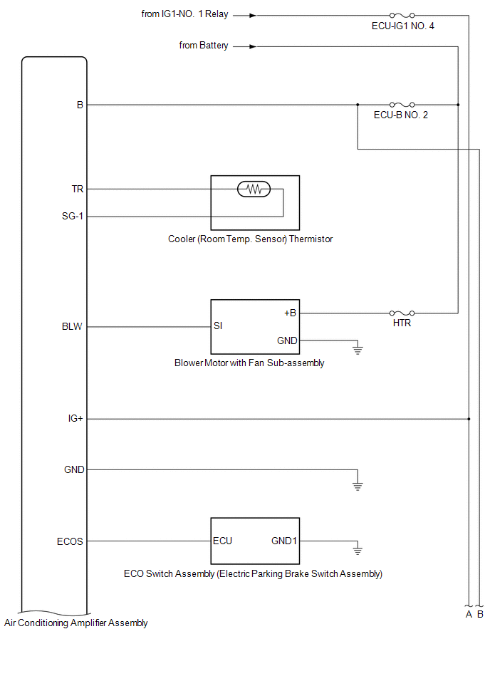
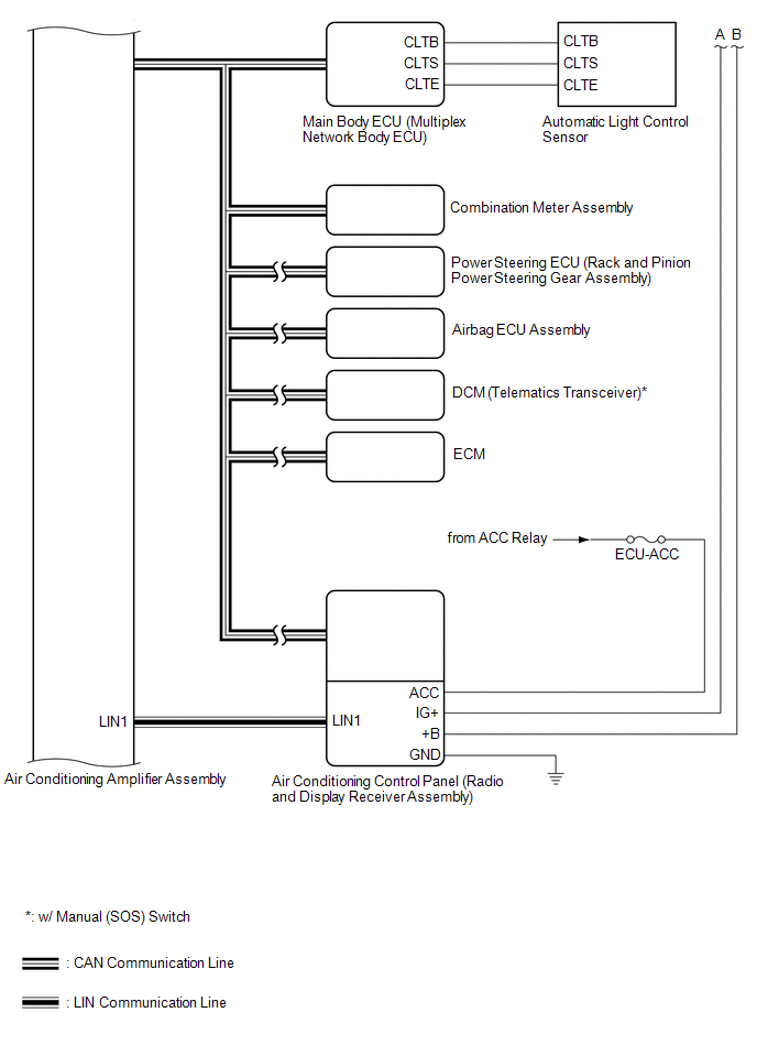
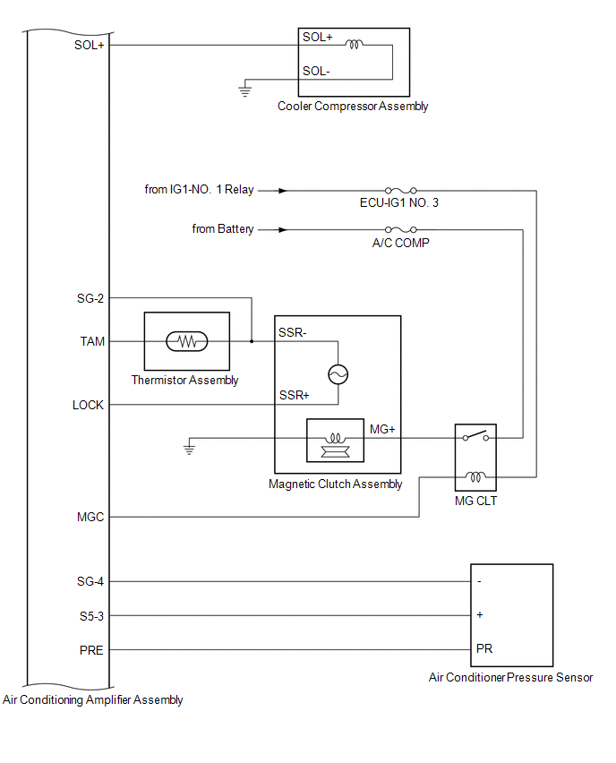
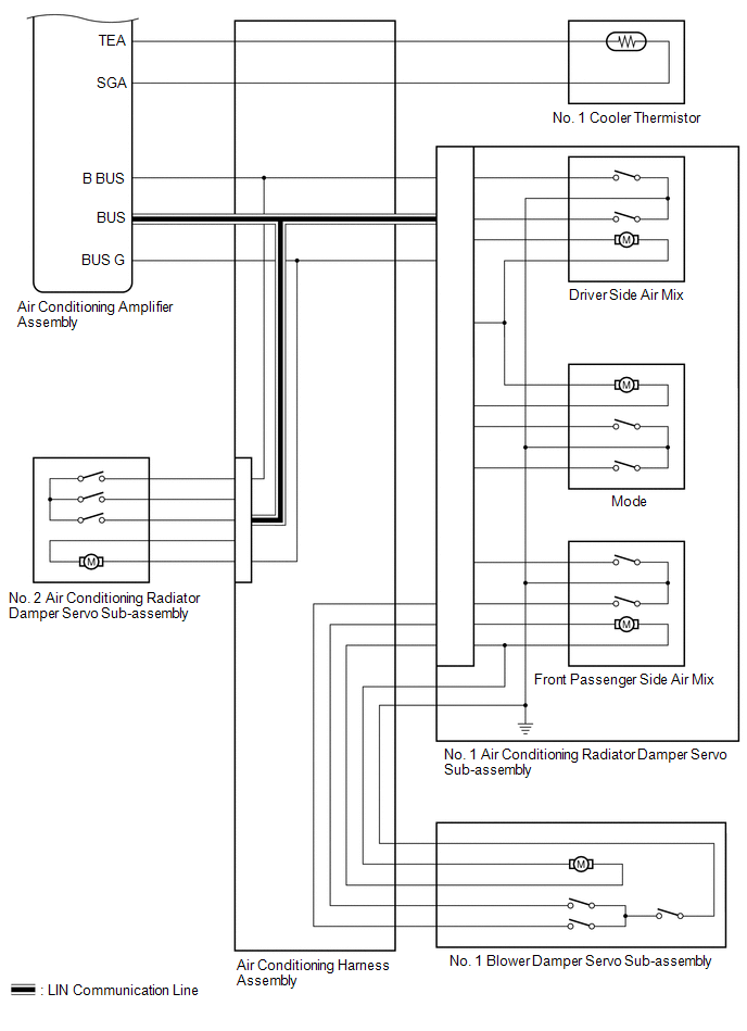
TERMINALS OF ECU
CHECK AIR CONDITIONING AMPLIFIER ASSEMBLY
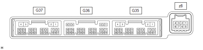
HINT:
Check from the rear of the connector while it is connected to the air conditioning amplifier assembly.
|
Terminal No. (Symbol) |
Wiring Color | Terminal Description |
Condition | Specified Condition |
|---|---|---|---|---|
|
G36-1 (SG-1) - Body ground |
LG - Body ground | Ground for cooler (room temp. sensor) thermistor |
Always | Below 1 V |
|
G36-2 (SG-2) - Body ground |
W - Body ground | Ground for thermistor assembly |
Always | Below 1 V |
|
G36-3 (SG-4) - Body ground |
L - Body ground | Ground for air conditioner pressure sensor |
Always | Below 1 V |
|
G36-6 (S5-3) - G36-3 (SG-4) |
GR - L | Power supply for air conditioner pressure sensor |
Engine switch on (IG) |
4.75 to 5.25 V |
| Engine switch off |
Below 1 V | |||
|
G36-9 (MGC) - G35-4 (GND) |
G - W-B | Magnetic clutch operation signal |
| 11 to 14 V |
| Below 1 V | |||
|
G36-13 (TAM) - G36-2 (SG-2) |
R - W | Thermistor assembly signal |
| 1.05 to 1.45 V |
| 0.64 to 0.87 V | |||
|
G36-14 (TR) - G36-1 (SG-1) |
GR - LG | Cooler (room temp. sensor) thermistor signal |
| 1.05 to 1.45 V |
| 0.64 to 0.87 V | |||
|
G36-20 (ECOS) - G35-4 (GND) |
W - W-B | ECO switch assembly (electric parking brake switch assembly) signal |
| 11 to 14 V |
| Below 1 V | |||
|
G36-21 (LOCK) - G36-2 (SG-2) |
B - W | A/C lock sensor signal |
| Pulse generation (See waveform 1) |
|
G36-24 (PRE) - G36-3 (SG-4) |
W - L | Air conditioner pressure sensor signal |
| 4.61 V or higher |
| Below 0.74 V | |||
| 0.74 to 4.61 V | |||
|
G35-1 (B) - G35-4 (GND) |
LA-B - W-B | Power source (Back-up) |
Always | 11 to 14 V |
|
G35-2 (IG+) - G35-4 (GND) |
LA-GR - W-B | Power source (IG) |
Engine switch on (IG) |
11 to 14 V |
| Engine switch off |
Below 1 V | |||
|
G35-3 (SOL+) - G35-4 (GND) |
R - W-B | Compressor solenoid operation signal |
| Pulse generation (See waveform 2) |
|
G35-4 (GND) - Body ground |
W-B - Body ground | Ground for main power supply |
Always | Below 1 V |
|
G35-6 (BLW) - G35-4 (GND) |
LG - W-B | Blower motor speed control signal |
| Pulse generation (See waveform 3) |
|
G35-11 (CANH) - G35-12 (CANL) |
SB - W | CAN communication system |
CAN communication is performed |
Pulse generation |
|
G35-14 (LIN1) - G35-4 (GND) |
LG - W-B | LIN communication signal |
Engine switch on (IG) |
Pulse generation (See waveform 4) |
|
z8-2 (BUS G) - Body ground |
B - Body ground | Ground for BUS IC |
Always | Below 1 V |
|
z8-3 (BUS) - z8-2 (BUS G) |
L - B | BUS IC control signal |
Engine switch on (IG) |
Pulse generation (See waveform 5) |
|
z8-4 (B BUS) - z8-2 (BUS G) |
R - B | Power supply for BUS IC |
Engine switch off | 11 to 14 V |
|
z8-5 (SGA) - Body ground |
GR - Body ground | Ground for No. 1 cooler thermistor |
Always | Below 1 V |
|
z8-6 (TEA) - z8-5 (SGA) |
GR - GR | No. 1 cooler thermistor signal |
| 1.7 to 2.1 V |
| 0.9 to 1.3 V |
(a) Waveform 1:
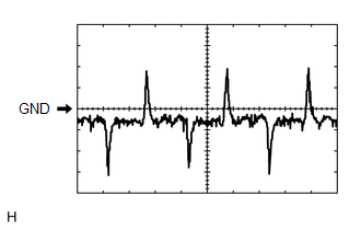
|
Item | Content |
|---|---|
|
Terminal No. | G36-21 (LOCK) - G36-2 (SG-2) |
|
Tool Setting | 200 mV/DIV., 10 ms./DIV. |
|
Condition |
|
(b) Waveform 2:
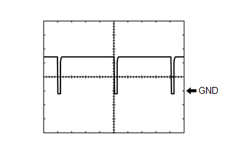
|
Item | Content |
|---|---|
|
Terminal No. | G35-3 (SOL+) - G35-4 (GND) |
|
Tool Setting | 5 V/DIV., 500 μs./DIV. |
|
Condition |
|
(c) Waveform 3:
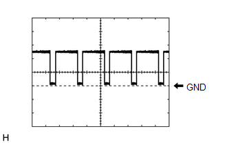
|
Item | Content |
|---|---|
|
Terminal No. | G35-6 (BLW) - G35-4 (GND) |
|
Tool Setting | 2 V/DIV., 1 ms./DIV. |
|
Condition |
|
(d) Waveform 4:

|
Item | Content |
|---|---|
|
Terminal No. | G35-14 (LIN1) - G35-4 (GND) |
|
Tool Setting | 2 V/DIV., 20 ms./DIV. |
|
Condition | Engine switch on (IG) |
(e) Waveform 5:
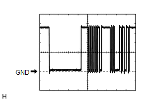
|
Item | Content |
|---|---|
|
Terminal No. | z8-3 (BUS) - z8-2 (BUS G) |
|
Tool Setting | 2 V/DIV., 2 ms./DIV. |
|
Condition | Engine switch on (IG) |
CHECK AIR CONDITIONING CONTROL PANEL (RADIO AND DISPLAY RECEIVER ASSEMBLY)

HINT:
Check from the rear of the connector while it is connected to the air conditioning control assembly.
|
Terminal No. (Symbol) |
Wiring Color | Terminal Description |
Condition | Specified Condition |
|---|---|---|---|---|
|
G20-2 (IG+) - G20-6 (GND) |
GR - W-B | Power source (IG) |
Engine switch off | Below 1 V |
|
Engine switch on (IG) |
11 to 14 V | |||
|
G20-3 (+B) - G20-6 (GND) |
L - W-B | Power source (Back-up) |
Engine switch off | 11 to 14 V |
|
G20-6 (GND) - Body ground |
W-B - Body ground | Ground for air conditioning control panel (radio and display receiver assembly) |
Always | Below 1 V |
|
G20-8 (LIN1) - Body ground |
LG - Body ground | LIN communication signal |
Engine switch on (IG) |
Pulse generation (See waveform) |
|
G20-10 (ACC) - G20-6 (GND) |
P - W-B | Power source (ACC) |
Engine switch off | Below 1 V |
|
Engine switch ACC | 11 to 14 V | |||
|
G20-11 (ILL+) - Body ground |
W - Body ground |
Illumination signal | Taillight off |
Below 1 V |
| Taillight on |
11 to 14 V | |||
|
G20-15 (ILL-) - Body ground |
B - Body ground | Illumination signal |
Always | Below 1 V |
(a) Waveform:
|
Item | Content |
|---|---|
|
Terminal No. | G20-8 (LIN1) - Body ground |
|
Tool Setting | 2 V/DIV., 20 ms./DIV. |
|
Condition | Engine switch on (IG) |
DESCRIPTION
|
DTC No. | Detection Item |
DTC Detection Condition | Trouble Area |
Memory |
|---|---|---|---|---|
| U0100 |
Lost Communication With ECM/PCM "A" |
No communication with ECM |
| Memorized |
|
U0131 | Lost Communication With Power Steering Control Module |
No communication with power steering ECU (rack and pinion power steering gear assembly) |
| Memorized |
|
U0142 | Lost Communication With Body Control Module "B" |
No communication with main body ECU (multiplex network body ECU) |
| Memorized |
|
U0151 | Lost Communication With Restraints Control Module |
No communication with airbag ECU assembly |
| Memorized |
|
U0155 | Lost Communication With Instrument Panel Cluster (IPC) Control Module |
No communication with combination meter assembly |
| Memorized |
|
U0163 | Lost Communication With Navigation Control Module |
No communication with air conditioning control panel (radio and display receiver assembly) |
| Memorized |
PROCEDURE
| 1. |
GO TO CAN COMMUNICATION SYSTEM |
HINT:
Refer to CAN Communication System.
Click here

| NEXT |  |
END |
UTILITY
REFRIGERANT HIGH PRESSURE HISTORY CLEAR
(a) Connect the Techstream to the DLC3.
(b) Turn the engine switch on (IG).
(c) Press the OFF switch.
(d) Turn the Techstream on.
(e) Enter the following menus: Body Electrical / Air Conditioner / Utility / Refrigerant High Pressure History Clear.
Body Electrical > Air Conditioner > Utility|
Tester Display |
|---|
| Refrigerant High Pressure History Clear |
REFRIGERANT SHORTAGE CHECK USING TECHSTREAM
(a) Connect the Techstream to the DLC3.
(b) Turn the engine switch on (IG).
(c) Turn the Techstream on.
(d) Enter the following menus: Body Electrical / Air Conditioner / Utility / Refrigerant Gas Volume Check.
Body Electrical > Air Conditioner > Utility|
Tester Display |
|---|
| Refrigerant Gas Volume Check |
(e) Check that the following conditions are met and perform the refrigerant shortage check according to the display on the Techstream.
Measurement Condition:|
Item | Condition |
|---|---|
|
A/C switch | On |
|
Ambient temperature* |
0 to 49°C (32 to 120°F) |
|
Blower speed | HI |
*: If the ambient temperature is not within the range shown, do not perform this check.
HINT:
|
Result | Amount of Refrigerant |
Corrective Action |
|---|---|---|
|
Refrigerant shortage |
Insufficient |
|
| Refrigerant correct |
Correct | - |
DESCRIPTION
If the airflow from the front registers is weak regardless of the blower speed setting displayed on the air conditioning control panel (radio and display receiver assembly), the following factors may be the cause.
|
Symptom | Factor |
|---|---|
|
|
PROCEDURE
| 1. |
CHECK AIR CONDITIONING SYSTEM |
(a) Operate the blower switch with the following conditions met and check that the airflow volume changes.
|
Blower Speed | Condition |
|---|---|
|
LO → HI |
|
OK:
Airflow volume increases.
| NG |  | GO TO OTHER DIAGNOSIS PROCEDURE (Blower Motor Circuit) |
|
| 2. |
CHECK ECO MODE SETTING |
(a) Check if the ECO mode indicator is off.
OK:
The ECO mode indicator is off.
| OK | | GO TO STEP 4 |
|
| 3. |
CHECK ECO MODE CONTROL OPERATION |
(a) Operate the ECO switch assembly (electric parking brake switch assembly) and check that the ECO mode indicator turns off and the blower speed reduction is canceled.
HINT:
|
Control |
Outline |
|---|---|
|
Blower Control |
When the air conditioning system is in AUTO mode, the blower speed will be reduced to a certain speed. Additionally, if warm-up control is operating, the blower speed will be further reduced. |
|
Air Inlet Control |
If the ambient temperature is a certain value or more, the air inlet mode will be changed to recirculation mode. |
|
Result | Proceed to |
|---|---|
|
ECO mode indicator turns off and blower speed reduction is canceled |
A |
| ECO mode indicator turns off, but the blower speed reduction is not canceled |
B |
| ECO mode indicator does not turn off |
| B |
| GO TO ECO Switch Circuit |
|
| 4. |
CHECK CLEAN AIR FILTER |
(a) Visually check the clean air filter.
Click here 
OK:
The clean air filter is not dirty or clogged.
| NG | | REPLACE CLEAN AIR FILTER |
|
| 5. |
CHECK NO. 1 COOLER THERMISTOR |
(a) Check the installation condition of the No. 1 cooler thermistor.
OK:
The No. 1 cooler thermistor is installed correctly.
| NG | | INSTALL NO. 1 COOLER THERMISTOR CORRECTLY |
|
| 6. |
CHECK ASPIRATOR |
(a) Check the installation condition of the aspirator.
OK:
The aspirator is installed correctly.
| OK | | REPLACE HEATER RADIATOR UNIT SUB-ASSEMBLY OR NO. 1 COOLER EVAPORATOR SUB-ASSEMBLY |
| NG | | INSTALL ASPIRATOR CORRECTLY |
Toyota Avalon (XX50) 2019-2022 Service & Repair Manual > Can Communication System(for Hv Model): Check Bus 1 Lines for Short Circuit
DESCRIPTION There may be a short circuit between the CAN main bus lines and/or CAN branch lines when the resistance between terminals 23 (CA1H) and 8 (CA1L) of the central gateway ECU (network gateway ECU) is below 54 Ω. Symptom Trouble Area Resistance between terminals 23 (CA1H) and 8 (CA1L) of th ...


