REMOVAL CAUTION / NOTICE / HINT The necessary procedures (adjustment, calibration, initialization or registration) that must be performed after parts are removed and installed, or replaced during compressor with motor assembly removal/installation are shown below. Necessary Procedure After Parts Removed/Installed/Replaced
CAUTION:
NOTICE: After turning the power switch off, waiting time may be required before disconnecting the cable from the negative (-) auxiliary battery terminal. Therefore, make sure to read the disconnecting the cable from the negative (-) auxiliary battery terminal notices before proceeding with work. Click here PROCEDURE 1. RECOVER REFRIGERANT FROM REFRIGERATION SYSTEM Click here
2. REMOVE SERVICE PLUG GRIP Click here
3. CHECK TERMINAL VOLTAGE (a) Disconnect the engine room main wire. Click here (b) Remove the connector cover assembly. Click here (c) Check the terminal voltage. Click here (d) Install the connector cover assembly. Click here (e) Connect the engine room main wire. Click here 4. REMOVE RADIATOR ASSEMBLY Click here 5. DISCONNECT SUCTION HOSE SUB-ASSEMBLY
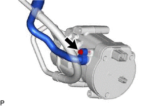
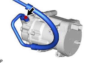
(b) Remove the O-ring from the suction hose sub-assembly. NOTICE: Seal the openings of the disconnected parts using vinyl tape to prevent moisture and foreign matter from entering them. 6. DISCONNECT NO. 1 COOLER REFRIGERANT DISCHARGE HOSE SUB-ASSEMBLY
(b) Remove the O-ring from the No. 1 cooler refrigerant discharge hose sub-assembly. NOTICE: Seal the openings of the disconnected parts using vinyl tape to prevent moisture and foreign matter from entering them. 7. REMOVE COMPRESSOR WITH MOTOR ASSEMBLY (a) Using a screwdriver, slide the green-colored lock of the connector (A) as shown in the illustration to release it and disconnect the connector. 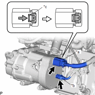
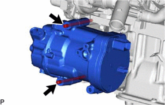
CAUTION: Make sure to wear insulated gloves. NOTICE: Insulate the disconnected terminals and connector with insulating tape. (b) Disconnect the connector (B). (c) Remove the bolt and 2 nuts. 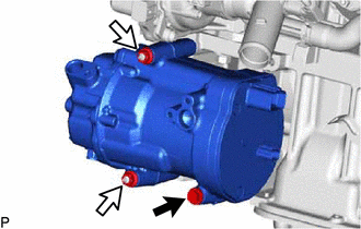
| |||||||||||||||||||||||||||||||||||||||||||||||||||||||||
Toyota Avalon (XX50) 2019-2022 Service & Repair Manual > Fuel Lid Opener System(for Gasoline Model): How To Proceed With Troubleshooting
CAUTION / NOTICE / HINT HINT: Use the following procedure to troubleshoot the fuel lid opener system. *: Use the Techstream. PROCEDURE 1. VEHICLE BROUGHT TO WORKSHOP NEXT 2. CUSTOMER PROBLEM ANALYSIS HINT: In troubleshooting, confirm that the problem symptoms have been accurately identified. Preconc ...