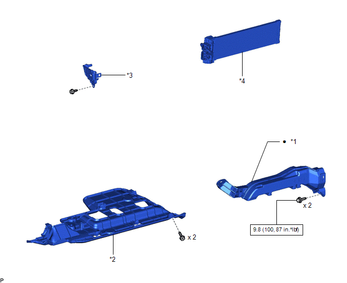
COMPONENTS
ILLUSTRATION
|
*1 | NO. 1 AIR DUCT |
*2 | NO. 1 INSTRUMENT PANEL UNDER COVER SUB-ASSEMBLY |
|
*3 | NO. 2 HEATER COVER |
*4 | QUICK HEATER ASSEMBLY |
 |
N*m (kgf*cm, ft.*lbf): Specified torque |
● | Non-reusable part |
INSPECTION
PROCEDURE
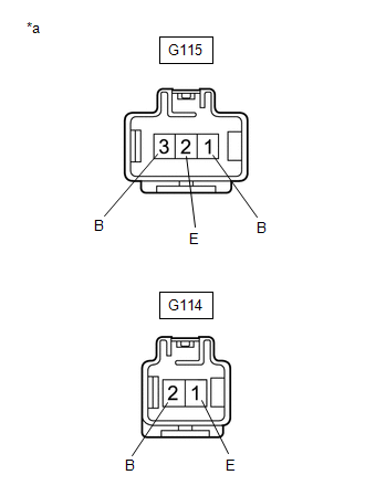
1. INSPECT QUICK HEATER ASSEMBLY
|
*a | Component without harness connected (Quick Heater Assembly) |
(a) Measure the resistance according to the value(s) in the table below.
Standard Resistance:
|
Tester Connection | Condition |
Specified Condition |
|---|---|---|
|
G115-1 (B) - G115-2 (E) |
Always | 10 kΩ or less |
|
G115-3 (B) - G114-1 (E) |
Always | 10 kΩ or less |
|
G115-3 (B) - G115-2 (E) |
Always | 10 kΩ or less |
|
G114-2 (B) - G114-1 (E) |
Always | 10 kΩ or less |
INSTALLATION
PROCEDURE
1. INSTALL QUICK HEATER ASSEMBLY
(a) Install the quick heater assembly as shown in the illustration.
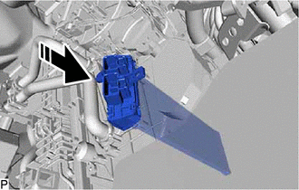
 |
Install in this Direction |
2. INSTALL NO. 2 HEATER COVER
(a) Engage the claw and 2 guides.
(b) Install the No. 2 heater cover with the screw.
(c) Engage the clamp.
(d) Connect the 2 connectors.
3. INSTALL NO. 1 AIR DUCT
for Manual Tilt and Manual Telescopic Steering Column:
Click here

for Power Tilt and Power Telescopic Steering Column:
Click here
4. INSTALL NO. 1 INSTRUMENT PANEL UNDER COVER SUB-ASSEMBLY
Click here
REMOVAL
PROCEDURE
1. REMOVE NO. 1 INSTRUMENT PANEL UNDER COVER SUB-ASSEMBLY
Click here 
2. REMOVE NO. 1 AIR DUCT
for Manual Tilt and Manual Telescopic Steering Column:
Click here
for Power Tilt and Power Telescopic Steering Column:
Click here
3. REMOVE NO. 2 HEATER COVER
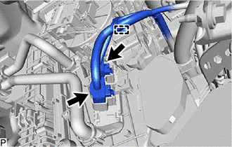
| (a) Disconnect the 2 connectors. |
|
(b) Disengage the clamp.
|
(c) Remove the screw. |
|
(d) Disengage the claw and 2 guides to remove the No. 2 heater cover.
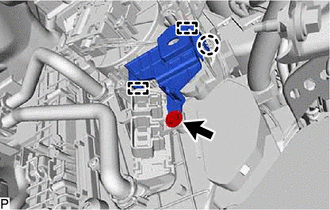
4. REMOVE QUICK HEATER ASSEMBLY
(a) Remove the quick heater assembly as shown in the illustration.
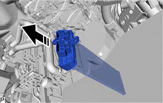
 | Remove in this Direction |
Toyota Avalon (XX50) 2019-2022 Service & Repair Manual > Motor Generator Control System: DC/DC Converter Current Sensor Signal Bias Level Out of Range / Zero Adjustment Failure (P0E5128). DC/DC Converter Voltage Sensor "A"(VL) Circuit Voltage Above Threshold (P0E5717). DC/DC Converter Tem
DC/DC Converter Current Sensor Signal Bias Level Out of Range / Zero Adjustment Failure (P0E5128) DTC SUMMARY MALFUNCTION DESCRIPTION This DTC is stored when an abnormal current sensor output signal is detected. The cause of this malfunction may be one of the following: Internal inverter malfunction ...