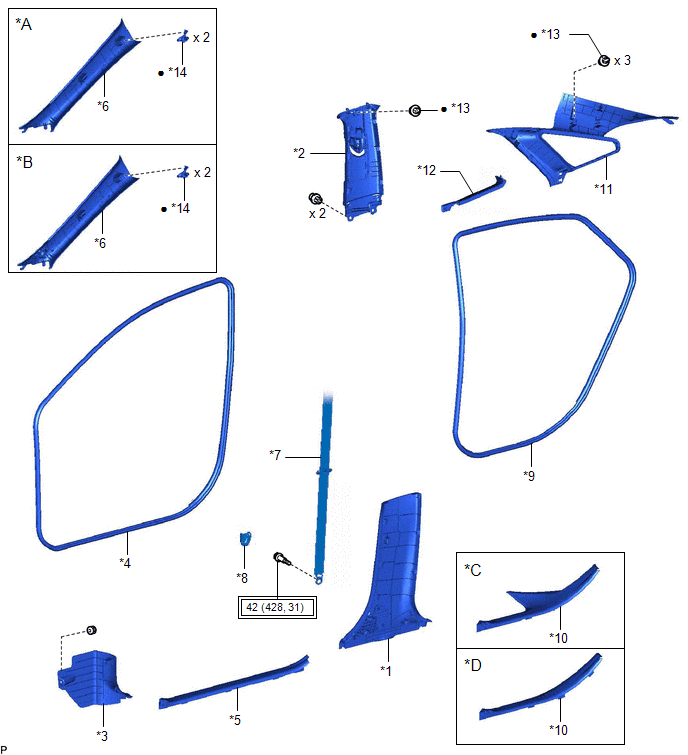
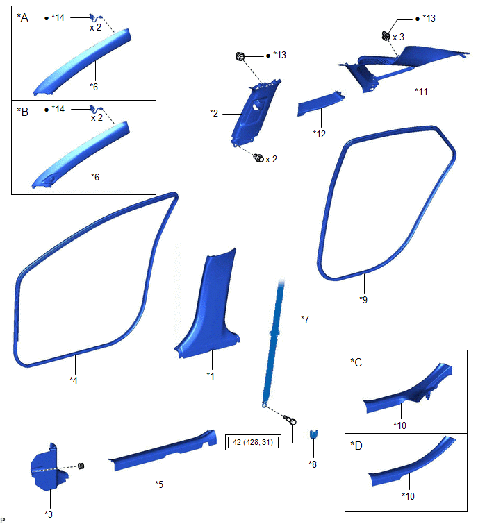
COMPONENTS
ILLUSTRATION
|
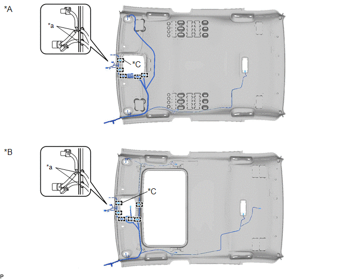
*A | w/o Front No. 3 Speaker |
*B | w/ Front No. 3 Speaker |
|
*C | for Gasoline Model |
*D | for HV Model |
|
*1 | CENTER PILLAR LOWER GARNISH LH |
*2 | CENTER PILLAR UPPER GARNISH LH |
|
*3 | COWL SIDE TRIM SUB-ASSEMBLY LH |
*4 | FRONT DOOR OPENING TRIM WEATHERSTRIP LH |
|
*5 | FRONT DOOR SCUFF PLATE LH |
*6 | FRONT PILLAR GARNISH LH |
|
*7 | FRONT SEAT OUTER BELT ASSEMBLY LH |
*8 | LAP BELT OUTER ANCHOR COVER |
|
*9 | REAR DOOR OPENING TRIM WEATHERSTRIP LH |
*10 | REAR DOOR SCUFF PLATE LH |
|
*11 | ROOF SIDE INNER GARNISH LH |
*12 | ROOF SIDE RAIL GARNISH ASSEMBLY LH |
|
*13 | CLIP |
*14 | FRONT PILLAR GARNISH CLIP |
 |
Tightening torque for "Major areas involving basic vehicle performance such as moving/turning/stopping": N*m (kgf*cm, ft.*lbf) |
● | Non-reusable part |
ILLUSTRATION
|
*A | w/o Front No. 3 Speaker |
*B | w/ Front No. 3 Speaker |
|
*C | for Gasoline Model |
*D | for HV Model |
|
*1 | CENTER PILLAR LOWER GARNISH RH |
*2 | CENTER PILLAR UPPER GARNISH RH |
|
*3 | COWL SIDE TRIM SUB-ASSEMBLY RH |
*4 | FRONT DOOR OPENING TRIM WEATHERSTRIP RH |
|
*5 | FRONT DOOR SCUFF PLATE RH |
*6 | FRONT PILLAR GARNISH RH |
|
*7 | FRONT SEAT OUTER BELT ASSEMBLY RH |
*8 | LAP BELT OUTER ANCHOR COVER |
|
*9 | REAR DOOR OPENING TRIM WEATHERSTRIP RH |
*10 | REAR DOOR SCUFF PLATE RH |
|
*11 | ROOF SIDE INNER GARNISH RH |
*12 | ROOF SIDE RAIL GARNISH ASSEMBLY RH |
|
*13 | CLIP |
*14 | FRONT PILLAR GARNISH CLIP |
|
|
Tightening torque for "Major areas involving basic vehicle performance such as moving/turning/stopping": N*m (kgf*cm, ft.*lbf) |
● | Non-reusable part |
ILLUSTRATION
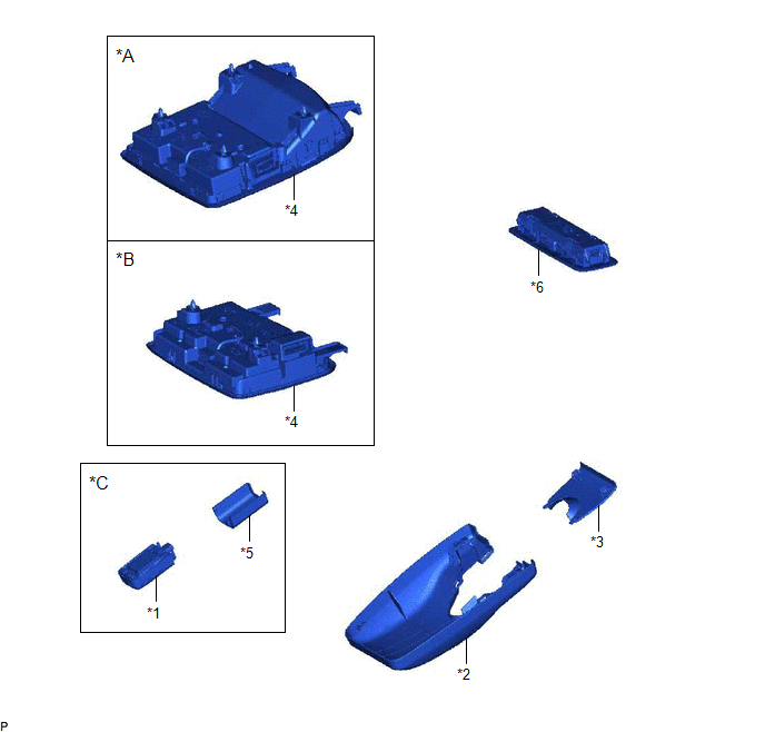
|
*A | for Normal Roof |
*B | for Moon Roof |
|
*C | w/ Humidity Sensor |
- | - |
|
*1 | AIR CONDITIONING THERMISTOR ASSEMBLY |
*2 | NO. 1 FORWARD RECOGNITION COVER |
|
*3 | NO. 2 FORWARD RECOGNITION COVER |
*4 | ROOF CONSOLE BOX ASSEMBLY |
|
*5 | SENSOR COVER |
*6 | SPOT LIGHT ASSEMBLY |
ILLUSTRATION
|
*A | for Moon Roof |
- | - |
|
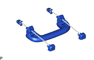
*1 | ASSIST GRIP SUB-ASSEMBLY |
*2 | REAR ASSIST GRIP ASSEMBLY LH |
|
*3 | REAR ASSIST GRIP ASSEMBLY RH |
*4 | SUN ROOF OPENING TRIM MOULDING |
|
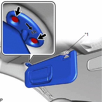
*5 | VISOR ASSEMBLY LH |
*6 | VISOR ASSEMBLY RH |
|
*7 | VISOR BRACKET COVER LH |
*8 | VISOR BRACKET COVER RH |
|
*9 | VISOR HOLDER LH |
*10 | VISOR HOLDER RH |
|
*11 | ASSIST GRIP COVER LH |
*12 | ASSIST GRIP COVER RH |
ILLUSTRATION
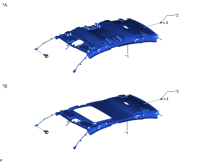
|
*A | for Normal Roof |
*B | for Moon Roof |
|
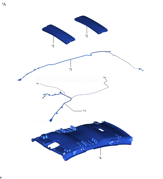
*1 | ROOF HEADLINING ASSEMBLY |
*2 | CLIP |
ILLUSTRATION
|
*A | for Normal Roof |
- | - |
|
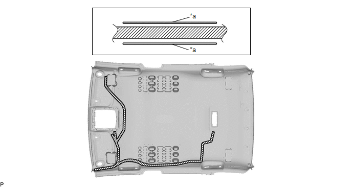
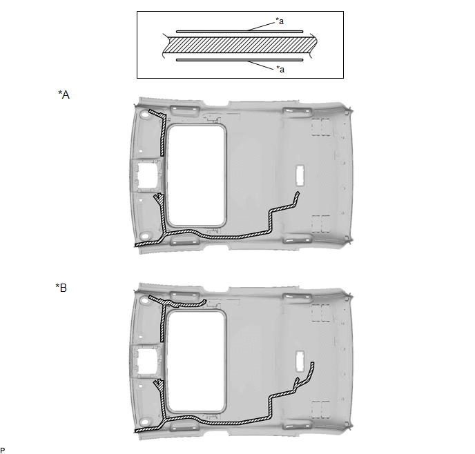
*1 | NO. 1 ROOF WIRE |
*2 | NO. 2 ROOF SILENCER |
|
*3 | NO. 3 ANTENNA CORD SUB-ASSEMBLY |
*4 | ROOF HEADLINING |
ILLUSTRATION
|
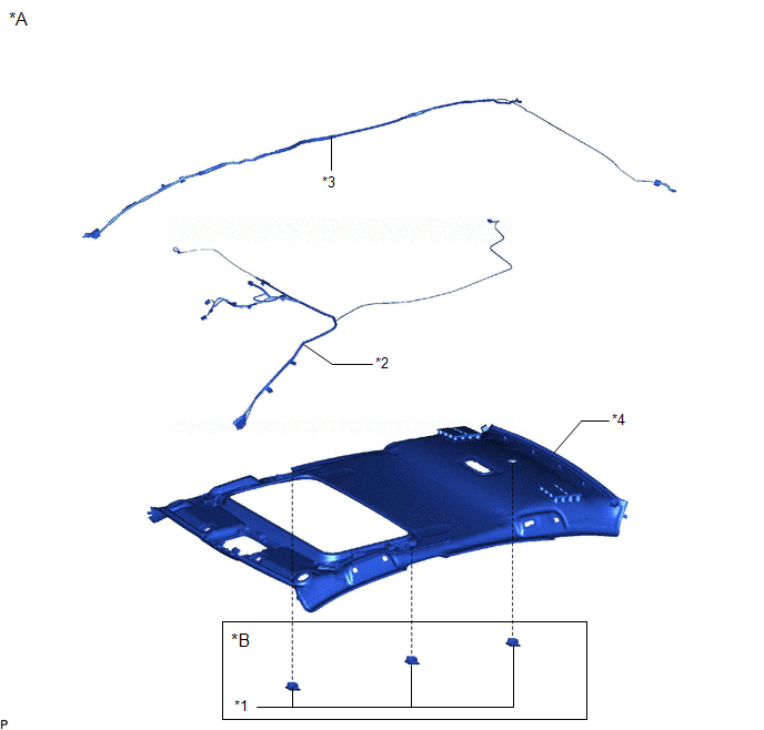
*A | for Moon Roof |
*B | w/ Active Noise Control System |
|
*1 | ACTIVE NOISE CONTROL MICROPHONE WITH COVER |
*2 | NO. 1 ROOF WIRE |
|
*3 | NO. 3 ANTENNA CORD SUB-ASSEMBLY |
*4 | ROOF HEADLINING |
DISASSEMBLY
PROCEDURE
1. REMOVE NO. 2 ROOF SILENCER (for Normal Roof)
(a) Remove the 2 No. 2 roof silencers.
2. REMOVE NO. 3 ANTENNA CORD SUB-ASSEMBLY
Click here 
3. REMOVE ACTIVE NOISE CONTROL MICROPHONE WITH COVER (w/ Active Noise Control System)
Click here
4. REMOVE NO. 1 ROOF WIRE
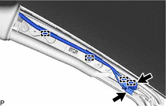
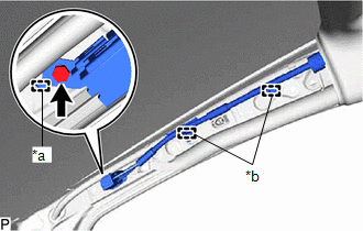
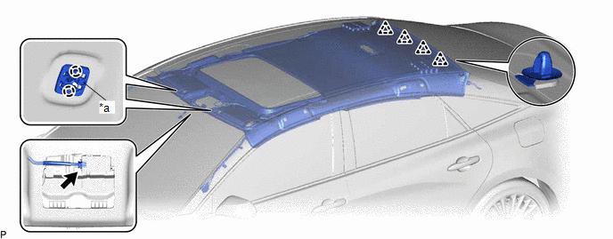
(a) Remove the adhesive tape from the roof headlining assembly.
|
*A | for Normal Roof |
*B | for Moon Roof |
|
*C | w/ Active Noise Control System |
- | - |
 |
Adhesive Tape | - |
- |
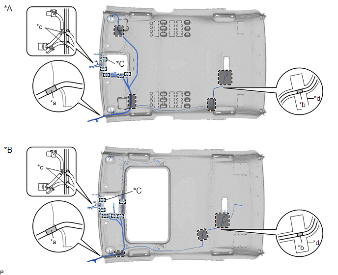
(b) Disengage the No. 1 roof wire from each notch.
|
*A | for Normal Roof |
*B | for Moon Roof |
|
*C | w/ Humidity Sensor |
- | - |
|
*a | Notch |
- | - |
(c) Disengage each clamp and remove the No. 1 roof wire from the roof headlining assembly.
INSTALLATION
PROCEDURE
1. INSTALL ROOF HEADLINING ASSEMBLY
| (a) Install the 4 clips to the roof headlining assembly. |
|
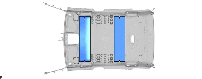
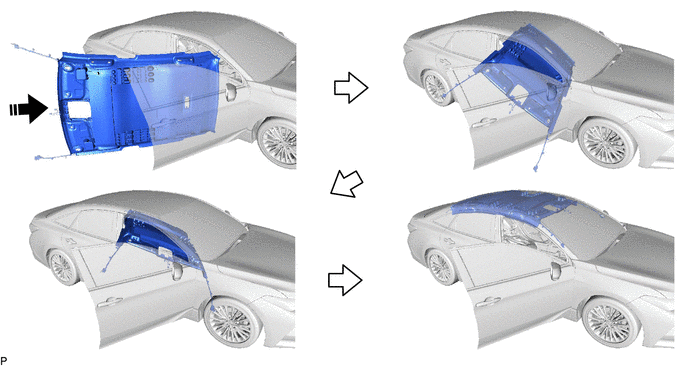
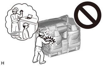
(b) Put the roof headlining assembly into the vehicle through the front door RH as shown in the illustration.
 |
Install in this Direction |
- | - |
NOTICE:
Do not damage the roof headlining assembly or vehicle interior.
(c) for Roof Side (for Normal Roof):
(1) Engage the 2 claws to install the base of each visor holder.
|
*a | Base of Visor Holder |
- | - |
(2) Engage the 4 clips and install the roof headlining assembly.
(d) for Roof Side (for Moon Roof):
(1) Engage the 2 claws to install the base of each visor holder.
|
*a | Base of Visor Holder |
- | - |
(2) Engage the 4 clips and install the roof headlining assembly.
(3) Connect the connector.
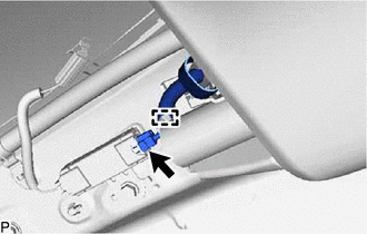
(e) for Rear Pillar LH Side:
(1) Engage the guide.
(2) Connect the connector.
(f) for Rear Pillar RH Side:
(1) Engage the guide.
(2) Connect each connector.
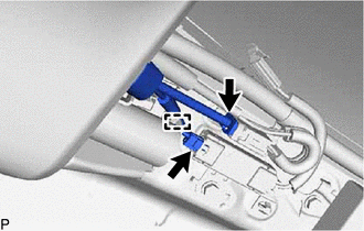
(g) for Front Pillar LH Side:
(1) Remove the protective cover.
(2) Engage the 4 clamps.
(3) Connect the 2 connectors.
(4) Install the protective cover.
(h) for Front Pillar RH Side:
(1) Remove the protective cover.
(2) Engage the 2 clamps.
(3) Engage the guide.
(4) Connect the connector bracket with the bolt.
(5) Install the protective cover.
(i) for Windshield Glass Side:
(1) Connect each connector.
2. INSTALL SUN ROOF OPENING TRIM MOULDING (for Moon Roof)
| (a) Align the alignment tape on the sun roof opening trim moulding with the notch of the roof headlining assembly and install the sun roof opening trim moulding. NOTICE: After installation, check that the corners fit correctly. |
|
3. INSTALL VISOR HOLDER LH
(a) Install the visor holder LH as shown in the illustration.
|
|
Install in this Direction |
4. INSTALL VISOR ASSEMBLY LH
NOTICE:
Make sure to install the visor assembly LH with its arrow facing the front of the vehicle.
(a) Connect the connector.
| (b) Connect the visor assembly LH to the visor holder LH. |
|
(c) for "TORX" Screw:
(1) Using a T25 "TORX" socket wrench, install the visor assembly LH with the 2 screws.
(d) except "TORX" Screw:
(1) Install the visor assembly LH with the 2 screws.
5. INSTALL VISOR BRACKET COVER LH
(a) Engage the 4 claws to install the visor bracket cover LH.
6. INSTALL VISOR HOLDER RH
HINT:
Use the same procedure as for the LH side.
7. INSTALL VISOR ASSEMBLY RH
HINT:
Use the same procedure as for the LH side.
8. INSTALL VISOR BRACKET COVER RH
HINT:
Use the same procedure as for the LH side.
9. INSTALL ASSIST GRIP SUB-ASSEMBLY
HINT:
Use the same procedure for all assist grip sub-assemblies.
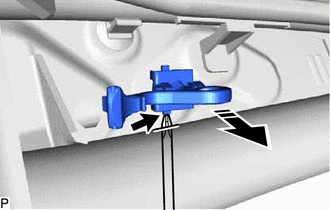
| (a) Install the 2 clips to the assist grip. |
|
(b) Temporarily install the 2 assist grip covers to the assist grip as shown in the illustration.
(c) Engage the 2 clips to install the assist grip sub-assembly as shown in the illustration.
|
|
Install in this Direction |
| (d) Engage the 4 claws to install the assist grip cover LH and assist grip cover RH. NOTICE: Make sure that the clip is engaged securely. |
|
10. INSTALL REAR ASSIST GRIP ASSEMBLY LH
HINT:
Use the same procedure as for the assist grip sub-assembly.
11. INSTALL REAR ASSIST GRIP ASSEMBLY RH
HINT:
Use the same procedure as for the assist grip sub-assembly.
12. INSTALL NO. 1 FORWARD RECOGNITION COVER
Click here

13. INSTALL NO. 2 FORWARD RECOGNITION COVER
Click here
14. INSTALL AIR CONDITIONING THERMISTOR ASSEMBLY (w/ Humidity Sensor)
Click here
15. INSTALL SENSOR COVER (w/ Humidity Sensor)
Click here
16. INSTALL SPOT LIGHT ASSEMBLY
Click here
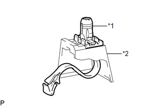
17. INSTALL ROOF CONSOLE BOX ASSEMBLY
Click here
18. INSTALL TRANSMISSION FLOOR SHIFT ASSEMBLY
for UA80E: Click here
for P710: Click here
19. INSTALL INSTRUMENT PANEL SAFETY PAD SUB-ASSEMBLY
Click here
20. INSTALL ROOF SIDE INNER GARNISH LH
(a) Install 3 new clips to the roof side inner garnish LH.
(b) Engage the guide as shown in the illustration.

|
|
Install in this Direction |
(c) Engage the 3 clips to install the roof side inner garnish LH as shown in the illustration.

|
|
Install in this Direction |
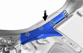
21. INSTALL ROOF SIDE RAIL GARNISH ASSEMBLY LH
(a) Engage the 3 guides and 3 claws as indicated by the arrows, in the order shown in the illustration to install the roof side rail garnish assembly LH.
|
|
Install in this Direction (1) |
 |
Install in this Direction (2) |
22. INSTALL CENTER PILLAR UPPER GARNISH LH
(a) Install a new clip to the center pillar upper garnish LH.
(b) Engage the 3 guides and clip as shown in the illustration.
|
|
Install in this Direction |
(c) Install the center pillar upper garnish LH with the 2 clips.
23. INSTALL CENTER PILLAR LOWER GARNISH LH
(a) Engage the 2 claws and 3 clips to install the center pillar lower garnish LH as shown in the illustration.
|
|
Install in this Direction |
24. CONNECT FRONT SEAT OUTER BELT ASSEMBLY LH
Click here
25. INSTALL LAP BELT OUTER ANCHOR COVER (for LH Side)
Click here
26. INSTALL REAR DOOR OPENING TRIM WEATHERSTRIP LH
Click here
27. INSTALL REAR DOOR SCUFF PLATE LH (for Gasoline Model)
(a) Engage the guide and 6 claws to install the rear door scuff plate LH as shown in the illustration.
|
|
Install in this Direction |
28. INSTALL REAR DOOR SCUFF PLATE LH (for HV Model)
(a) Engage the guide, 6 claws and clip to install the rear door scuff plate LH as shown in the illustration.
|
|
Install in this Direction |
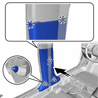
29. INSTALL FRONT PILLAR GARNISH LH
(a) Remove the protective cover.
| (b) Install 2 new front pillar garnish clips to the front pillar garnish LH. HINT: Make sure that the front pillar garnish clip is engaged correctly. |
|
(c) w/o Front No. 3 Speaker:
(1) Push the front pillar garnish LH as shown in the illustration to engage the 2 guides.
|
|
Install in this Direction |
(d) w/ Front No. 3 Speaker:
(1) Connect the connector.
(2) Push the front pillar garnish LH as shown in the illustration to engage the 2 guides.
(e) Engage the 2 front pillar garnish clips to install the front pillar garnish LH as shown in the illustration.
HINT:
Make sure that the curtain shield airbag assembly LH is not pinched.
|
*1 | Front Pillar Garnish Clip |
|
|
Install in this Direction |
30. INSTALL FRONT DOOR OPENING TRIM WEATHERSTRIP LH
Click here
31. INSTALL COWL SIDE TRIM SUB-ASSEMBLY LH
(a) Engage the claw and clip as shown in the illustration.
|
|
Install in this Direction |
(b) Install the cowl side trim sub-assembly LH with the clip.
32. INSTALL FRONT DOOR SCUFF PLATE LH
(a) Engage the guide and 10 claws to install the front door scuff plate LH as shown in the illustration.
|
|
Install in this Direction |
33. INSTALL ROOF SIDE INNER GARNISH RH
HINT:
Use the same procedure as for the LH side.
34. INSTALL ROOF SIDE RAIL GARNISH ASSEMBLY RH
HINT:
Use the same procedure as for the LH side.
35. INSTALL CENTER PILLAR UPPER GARNISH RH
HINT:
Use the same procedure as for the LH side.
36. INSTALL CENTER PILLAR LOWER GARNISH RH
HINT:
Use the same procedure as for the LH side.
37. CONNECT FRONT SEAT OUTER BELT ASSEMBLY RH
HINT:
Use the same procedure as for the LH side.
38. INSTALL LAP BELT OUTER ANCHOR COVER (for RH Side)
HINT:
Use the same procedure as for the LH side.
39. INSTALL REAR DOOR OPENING TRIM WEATHERSTRIP RH
HINT:
Use the same procedure as for the LH side.
40. INSTALL REAR DOOR SCUFF PLATE RH
HINT:
Use the same procedure as for the LH side.
41. INSTALL FRONT PILLAR GARNISH RH
HINT:
Use the same procedure as for the LH side.
42. INSTALL FRONT DOOR OPENING TRIM WEATHERSTRIP RH
HINT:
Use the same procedure as for the LH side.
43. INSTALL COWL SIDE TRIM SUB-ASSEMBLY RH
HINT:
Use the same procedure as for the LH side.
44. INSTALL FRONT DOOR SCUFF PLATE RH
HINT:
Use the same procedure as for the LH side.
45. INSTALL REAR SEAT ASSEMBLY
Click here
46. INSTALL FRONT SEAT ASSEMBLY
Click here
REASSEMBLY
PROCEDURE
1. INSTALL NO. 1 ROOF WIRE
(a) for Normal Roof:
|
*a |
Marking |
- |
- |
 |
Butyl Tape |
- |
- |
NOTICE:
Securely attach the butyl tape.
(b) for Moon Roof:
|
*A |
w/o Active Noise Control System |
*B |
w/ Active Noise Control System |
|
*a |
Marking |
- |
- |
|
|
Butyl Tape |
- |
- |
NOTICE:
Securely attach the butyl tape.
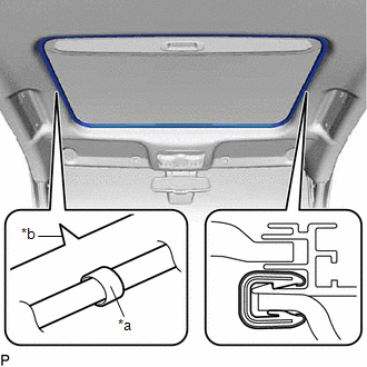
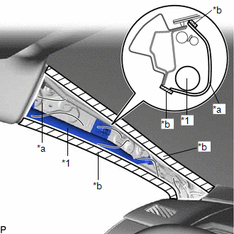
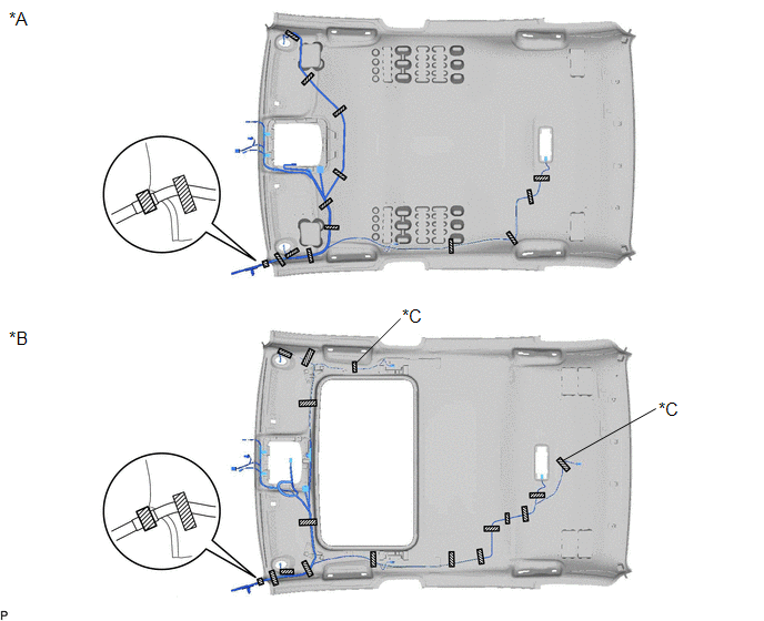
(c) Align the marking tape (A) on the No. 1 roof wire with the vehicle front side tab of the roof headlining.
|
*A | for Normal Roof |
*B | for Moon Roof |
|
*C | w/ Humidity Sensor |
- | - |
|
*a | Marking Tape (A) |
*b | Marking Tape (B) |
|
*c | Notch |
*d | Marking |
 |
Adjustment Area | - |
- |
(d) Engage each clamp.
(e) Engage the No. 1 roof wire to each notch of the roof headlining as shown in the illustration.
(f) Align the marking tape (B) on the No. 1 roof wire with the markings on the roof headlining.
(g) Attach the No. 1 roof wire with the butyl tape.
NOTICE:
HINT:
Secure the extra length of the No. 1 roof wire in the adjustment area.
(h) Install the No. 1 roof wire to the roof headlining with adhesive tape.
|
*A | for Normal Roof |
*B | for Moon Roof |
|
*C | w/ Active Noise Control System |
- | - |
|
*1 | No. 1 Roof Wire |
- | - |
|
*a | Correct |
*b | Incorrect |
|
*c | Marking |
*d | 10 mm (0.394 in.) or more |
|
|
Adhesive Tape | - |
- |
|
Area | Dimension |
Area | Dimension |
|---|---|---|---|
|
A | 20 mm (0.787 in.) |
B | 80 mm (3.15 in.) or more |
NOTICE:
2. INSTALL ACTIVE NOISE CONTROL MICROPHONE WITH COVER (w/ Active Noise Control System)
Click here 
3. INSTALL NO. 3 ANTENNA CORD SUB-ASSEMBLY
Click here
4. INSTALL NO. 2 ROOF SILENCER (for Normal Roof)
(a) Align the 2 No. 2 roof silencers with the markings on the roof headlining and install them using hot-melt glue as shown in the illustration.
|
*a | Hot-melt Glue |
*b | Marking |
REMOVAL
CAUTION / NOTICE / HINT
The necessary procedures (adjustment, calibration, initialization or registration) that must be performed after parts are removed and installed, or replaced during roof headlining removal/installation are shown below.
Necessary Procedure After Parts Removed/Installed/Replaced (for Gasoline Model)|
Replaced Part or Performed Procedure |
Necessary Procedure | Effect/Inoperative Function When Necessary Procedures are not Performed |
Link |
|---|---|---|---|
|
*: When performing learning using the Techstream.
Click here | |||
|
Disconnect cable from negative (-) battery terminal |
Perform steering sensor zero point calibration |
Lane Departure Alert System (w/ Steering Control) |
|
|
Pre-collision System | |||
|
Intelligent Clearance Sonar System* | |||
|
Lighting System (for Gasoline Model with Cornering Light) | |||
|
Memorize steering angle neutral point |
Parking Assist Monitor System |
| |
|
Panoramic View Monitor System |
| ||
|
Front passenger seat | Zero point calibration (Occupant classification system) |
|
|
|
Replaced Part or Performed Procedure |
Necessary Procedure | Effect/Inoperative Function When Necessary Procedures are not Performed |
Link |
|---|---|---|---|
|
*: When performing learning using the Techstream.
Click here | |||
|
Disconnect cable from negative (-) auxiliary battery terminal |
Perform steering sensor zero point calibration |
Lane Departure Alert System (w/ Steering Control) |
|
|
Pre-collision System | |||
|
Intelligent Clearance Sonar System* | |||
|
Lighting System (for HV Model with Cornering Light) | |||
|
Memorize steering angle neutral point |
Parking Assist Monitor System |
| |
|
Panoramic View Monitor System |
| ||
|
Front passenger seat | Zero point calibration (Occupant classification system) |
|
|
CAUTION:
Some of these service operations affect the SRS airbag system. Read the precautionary notices concerning the SRS airbag system before servicing.
for Gasoline Model: Click here

for HV Model: Click here
PROCEDURE
1. REMOVE FRONT SEAT ASSEMBLY
Click here
2. REMOVE REAR SEAT ASSEMBLY
Click here
3. REMOVE FRONT DOOR SCUFF PLATE LH
(a) Disengage the claw as shown in the illustration.
 |
Place Hand Here |
 |
Remove in this Direction |
HINT:
Use the same procedure for the front side and rear side.
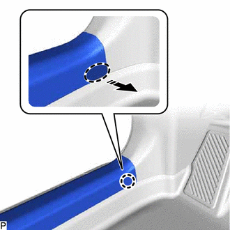
(b) Disengage the 8 claws and guide to remove the front door scuff plate LH as shown in the illustration.

|
|
Remove in this Direction |
4. REMOVE COWL SIDE TRIM SUB-ASSEMBLY LH
(a) Remove the clip.

|
|
Remove in this Direction |
(b) Disengage the claw and clip to remove the cowl side trim sub-assembly LH as shown in the illustration.
5. REMOVE FRONT DOOR OPENING TRIM WEATHERSTRIP LH
Click here
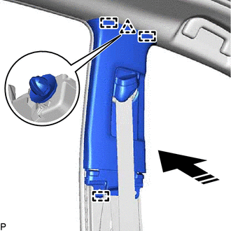
6. REMOVE FRONT PILLAR GARNISH LH
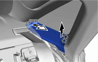
(a) Apply protective tape around the front pillar garnish LH as shown in the illustration.
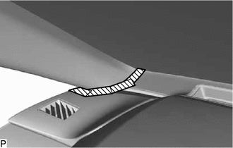
 | Protective Tape |
(b) Pull the upper part of the front pillar garnish LH toward the inside of the cabin as shown in the illustration to disengage the front pillar garnish LH from the base of the front pillar garnish clip.
HINT:
Let the front pillar garnish LH hang from the front pillar garnish clip.
|
*1 | Front Pillar Garnish Clip |
|
|
Remove in this Direction |
(c) While pushing the tabs of the front pillar garnish clip as shown in the illustration, disengage it.
|
*1 | Front Pillar Garnish Clip |
HINT:
When the front pillar garnish clip cannot be disengaged easily:
|
|
Move in this Direction |
|
|
Pull in this Direction |
(d) Disengage the front pillar garnish LH from the base of the front pillar garnish clip as shown in the illustration.
|
*1 | Front Pillar Garnish Clip |
|
|
Remove in this Direction |
(e) While pushing the tabs of the front pillar garnish clip as shown in the illustration, disengage it.
|
*1 | Front Pillar Garnish Clip |
|
|
Remove in this Direction |
HINT:
When the front pillar garnish clip cannot be disengaged easily:
|
|
Move in this Direction |
|
|
Pull in this Direction |
(f) w/o Front No. 3 Speaker:
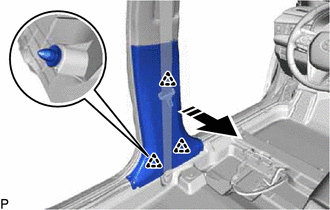
(1) Disengage the 2 guides to remove the front pillar garnish LH as shown in the illustration.
|
|
Remove in this Direction |
(g) w/ Front No. 3 Speaker:
(1) Disengage the 2 guides as shown in the illustration.
(2) Disconnect the connector to remove the front pillar garnish LH.
(h) Remove the 2 front pillar garnish clips from the front pillar garnish LH.
| (i) Protect the curtain shield airbag assembly LH. (1) Cover the curtain shield airbag assembly LH with a protective cover, such as a cloth, and secure the edges of the cover with tape as shown in the illustration. NOTICE: Cover the curtain shield airbag assembly LH with a protective cover as soon as the front pillar garnish LH is removed. |
|
7. REMOVE REAR DOOR SCUFF PLATE LH (for Gasoline Model)
(a) Disengage the claw as shown in the illustration.
|
|
Place Hand Here |
|
|
Remove in this Direction |
(b) Disengage the 5 claws and guide to remove the rear door scuff plate LH as shown in the illustration.

|
|
Remove in this Direction |
8. REMOVE REAR DOOR SCUFF PLATE LH (for HV Model)
(a) Disengage the claw as shown in the illustration.
|
|
Place Hand Here |
|
|
Remove in this Direction |
(b) Disengage the 5 claws, clip and guide to remove the rear door scuff plate LH as shown in the illustration.
|
|
Remove in this Direction |
9. REMOVE REAR DOOR OPENING TRIM WEATHERSTRIP LH
Click here
10. REMOVE LAP BELT OUTER ANCHOR COVER (for LH Side)
Click here
11. DISCONNECT FRONT SEAT OUTER BELT ASSEMBLY LH
Click here
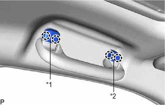
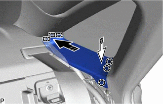
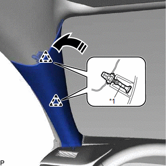
12. REMOVE CENTER PILLAR LOWER GARNISH LH
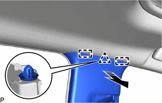
(a) Disengage the 2 claws as shown in the illustration.
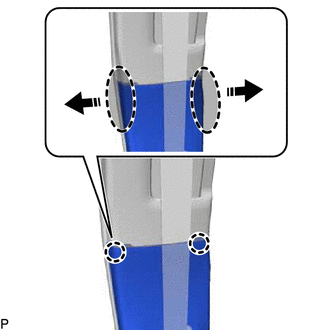
|
|
Place Hand Here |
|
|
Remove in this Direction |
(b) Disengage the 3 clips to remove the center pillar lower garnish LH as shown in the illustration.
|
|
Remove in this Direction |
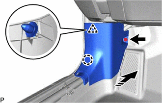
13. REMOVE CENTER PILLAR UPPER GARNISH LH
| (a) Using a clip remover, remove the 2 clips. |
|
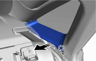
(b) Disengage the guide as shown in the illustration.
|
|
Place Hand Here |
|
|
Remove in this Direction |
(c) Disengage the clip and 2 guides as shown in the illustration.
|
|
Remove in this Direction |
(d) Pass the anchor of the front seat outer belt assembly LH through the center pillar upper garnish LH and remove the center pillar upper garnish LH.
(e) Remove the clip from the center pillar upper garnish LH.
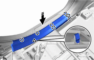
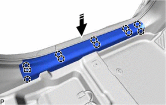
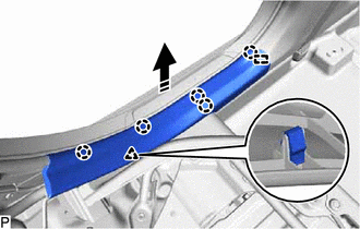
14. REMOVE ROOF SIDE RAIL GARNISH ASSEMBLY LH
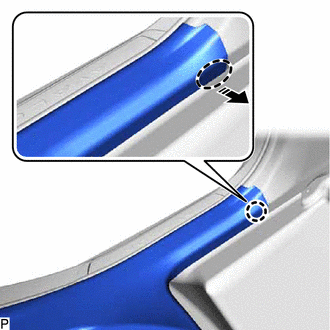
(a) Disengage the claw as shown in the illustration.
|
|
Remove in this Direction |
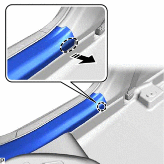
(b) Disengage the 2 claws and 3 guides as indicated by the arrows, in the order shown in the illustration to remove the roof side rail garnish assembly LH.
|
|
Remove in this Direction (1) |
 |
Remove in this Direction (2) |
15. REMOVE ROOF SIDE INNER GARNISH LH
(a) Disengage the 3 clips as shown in the illustration.
|
|
Remove in this Direction |
(b) Disengage the guide to remove the roof side inner garnish LH as shown in the illustration.
|
|
Remove in this Direction |
(c) Remove the 3 clips from the roof side inner garnish LH.
16. REMOVE FRONT DOOR SCUFF PLATE RH
HINT:
Use the same procedure as for the LH side.
17. REMOVE COWL SIDE TRIM SUB-ASSEMBLY RH
HINT:
Use the same procedure as for the LH side.
18. REMOVE FRONT DOOR OPENING TRIM WEATHERSTRIP RH
HINT:
Use the same procedure as for the LH side.
19. REMOVE FRONT PILLAR GARNISH RH
HINT:
Use the same procedure as for the LH side.
20. REMOVE REAR DOOR SCUFF PLATE RH
HINT:
Use the same procedure as for the LH side.
21. REMOVE REAR DOOR OPENING TRIM WEATHERSTRIP RH
HINT:
Use the same procedure as for the LH side.
22. REMOVE LAP BELT OUTER ANCHOR COVER (for RH Side)
HINT:
Use the same procedure as for the LH side.
23. DISCONNECT FRONT SEAT OUTER BELT ASSEMBLY RH
HINT:
Use the same procedure as for the LH side.
24. REMOVE CENTER PILLAR LOWER GARNISH RH
HINT:
Use the same procedure as for the LH side.
25. REMOVE CENTER PILLAR UPPER GARNISH RH
HINT:
Use the same procedure as for the LH side.
26. REMOVE ROOF SIDE RAIL GARNISH ASSEMBLY RH
HINT:
Use the same procedure as for the LH side.
27. REMOVE ROOF SIDE INNER GARNISH RH
HINT:
Use the same procedure as for the LH side.
28. REMOVE INSTRUMENT PANEL SAFETY PAD SUB-ASSEMBLY
Click here
29. REMOVE TRANSMISSION FLOOR SHIFT ASSEMBLY
for UA80E : Click here
for P710: Click here
30. REMOVE ROOF CONSOLE BOX ASSEMBLY
Click here
31. REMOVE SPOT LIGHT ASSEMBLY
Click here
32. REMOVE SENSOR COVER (w/ Humidity Sensor)
Click here
33. REMOVE AIR CONDITIONING THERMISTOR ASSEMBLY (w/ Humidity Sensor)
Click here
34. REMOVE NO. 2 FORWARD RECOGNITION COVER
Click here
35. REMOVE NO. 1 FORWARD RECOGNITION COVER
Click here
36. REMOVE ASSIST GRIP SUB-ASSEMBLY
HINT:
Use the same procedure for all assist grip sub-assemblies.
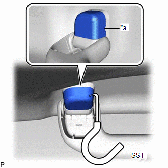
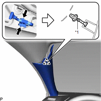
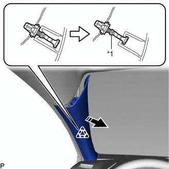
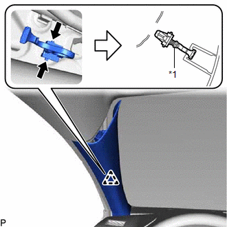
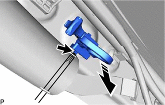
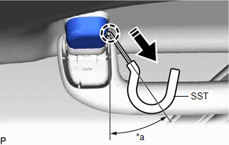
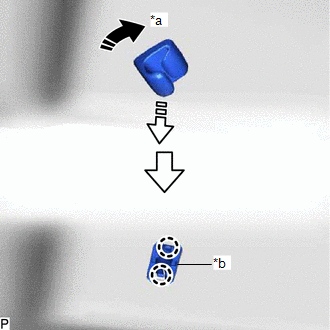
| (a) Insert SST into the cutout of the assist grip cover LH as shown in the illustration. SST: 09813-00010 NOTICE: To prevent the assist grip sub-assembly from being damaged, make sure to insert SST straight into the cutout. HINT: Use the same procedure for the LH side and RH side. |
|
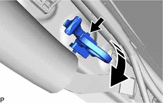
(b) Pull SST as shown in the illustration to disengage the claw.
NOTICE:
To prevent the assist grip sub-assembly from being damaged, make sure to only pull SST as shown in the illustration.
|
*a | 30 to 45° |
|
|
Remove in this Direction |
HINT:
(c) Remove the assist grip cover LH.
HINT:
Use the same procedure for the LH side and RH side.
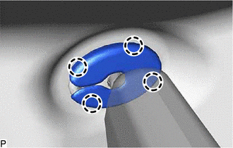
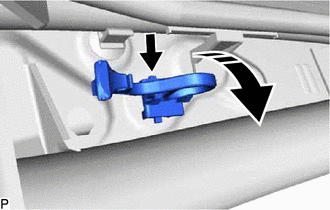
(d) Disengage the 2 clips as shown in the illustration to remove the assist grip sub-assembly.
|
|
Remove in this Direction |
(e) Remove the 2 clips from the vehicle body.
37. REMOVE REAR ASSIST GRIP ASSEMBLY LH
HINT:
Use the same procedure as for the assist grip sub-assembly.
38. REMOVE REAR ASSIST GRIP ASSEMBLY RH
HINT:
Use the same procedure as for the assist grip sub-assembly.
39. REMOVE VISOR BRACKET COVER LH
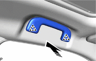
| (a) Disengage the 4 claws and remove the visor bracket cover LH. |
|
40. REMOVE VISOR ASSEMBLY LH
(a) for "TORX" Screw:
| (1) Using a T25 "TORX" socket wrench, remove the 2 screws. |
|
(b) except "TORX" Screw:
(1) Remove the 2 screws.
(c) Pull the visor assembly LH in the direction indicated by the arrow (1) shown in the illustration to disconnect it from the visor holder LH.
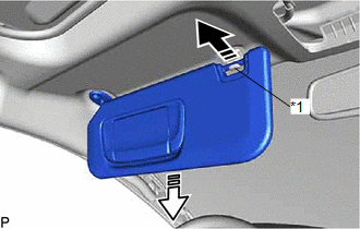
|
*1 | Visor Holder LH |
|
|
Remove in this Direction (1) |
|
|
Remove in this Direction (2) |
(d) Pull the visor assembly LH in the direction indicated by the arrow (2) shown in the illustration.
(e) Disconnect the connector to remove the visor assembly LH.
41. REMOVE VISOR HOLDER LH
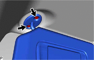
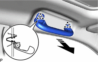
(a) Turn the visor holder LH approximately 45° and remove it as indicated by the arrows, in the order shown in the illustration.
|
*a | 45° |
|
*b | Base of the Visor Holder LH |
|
|
Remove in this Direction (1) |
|
|
Remove in this Direction (2) |
(b) Disengage the 2 claws to remove the base of the visor holder LH.
42. REMOVE VISOR BRACKET COVER RH
HINT:
Use the same procedure as for the LH side.
43. REMOVE VISOR ASSEMBLY RH
HINT:
Use the same procedure as for the LH side.
44. REMOVE VISOR HOLDER RH
HINT:
Use the same procedure as for the LH side.
45. REMOVE SUN ROOF OPENING TRIM MOULDING (for Moon Roof)
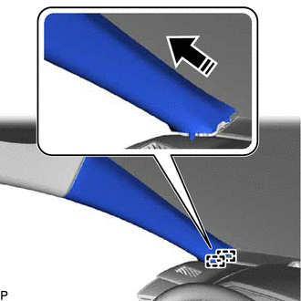
(a) Remove the sun roof opening trim moulding.
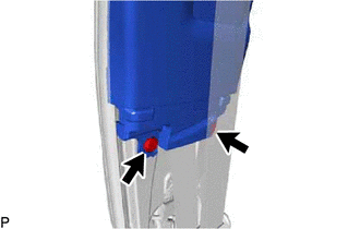
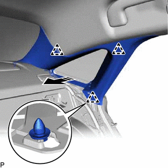
46. REMOVE ROOF HEADLINING ASSEMBLY
(a) for Windshield Glass Side:
(1) Disconnect each connector.
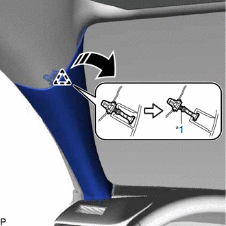
(b) for Front Pillar LH Side:
(1) Remove the protective cover.
| (2) Disconnect the 2 connectors. |
|
(3) Using a clip remover, disengage the 4 clamps.
(4) Install the protective cover.
(c) for Front Pillar RH Side:
(1) Remove the protective cover.
| (2) Remove the bolt. |
|
(3) Disengage the guide to disconnect the connector bracket.
(4) Using a clip remover, disengage the 2 clamps.
(5) Install the protective cover.
(d) for Rear Pillar LH Side:
| (1) Disconnect the connector. |
|
(2) Disengage the guide.
(e) for Rear Pillar RH Side:
| (1) Disconnect each connector. |
|
(2) Disengage the guide.
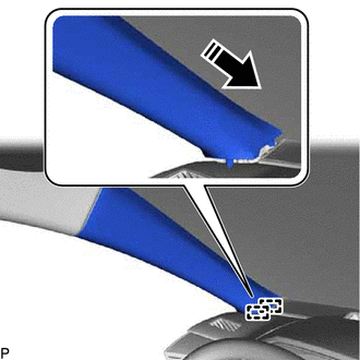
(f) for Roof Side (for Normal Roof):
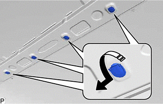
(1) Slide the roof headlining assembly to disengage it from the 4 clips as shown in the illustration.
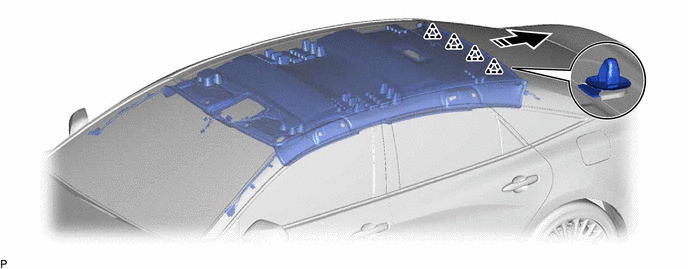
|
|
Remove in this Direction |
- | - |
HINT:
Leave the 4 clips installed to the vehicle body.
(g) for Roof Side (for Moon Roof):
(1) Disconnect the connector.
|
|
Remove in this Direction |
- | - |
(2) Slide the roof headlining assembly to disengage it from the 4 clips as shown in the illustration.
HINT:
Leave the 4 clips installed to the vehicle body.
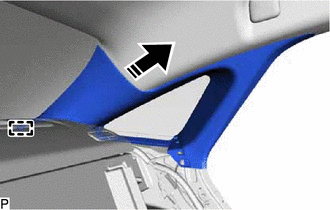
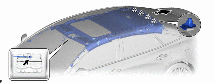
(h) Remove the roof headlining assembly from the vehicle through the front door RH as shown in the illustration.
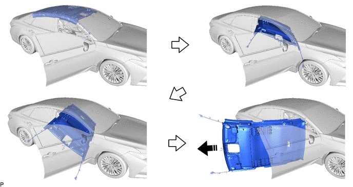
|
|
Remove in this Direction |
- | - |
NOTICE:
Do not damage the roof headlining assembly or vehicle interior.
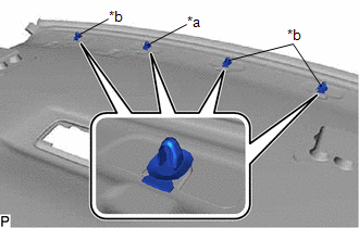
(i) Remove the 4 clips from the vehicle body as shown in the illustration.
|
|
Remove in this Direction |
Toyota Avalon (XX50) 2019-2022 Service & Repair Manual > Audio And Visual System(for Gasoline Model): How To Proceed With Troubleshooting. Illumination Circuit. Illumination for Panel Switch does not Come on with Tail Switch ON
How To Proceed With Troubleshooting CAUTION / NOTICE / HINT HINT: Use the following procedure to troubleshoot the audio and visual system. *: Use the Techstream. PROCEDURE 1. VEHICLE BROUGHT TO WORKSHOP NEXT 2. CUSTOMER PROBLEM ANALYSIS When troubleshooting, check that the problem symptoms have been ...