REMOVAL CAUTION / NOTICE / HINT The necessary procedures (adjustment, calibration, initialization or registration) that must be performed after parts are removed and installed, or replaced during roof headlining removal/installation are shown below. Necessary Procedure After Parts Removed/Installed/Replaced (for Gasoline Model)
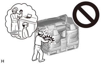
CAUTION: Some of these service operations affect the SRS airbag system. Read the precautionary notices concerning the SRS airbag system before servicing. for Gasoline Model: Click here
for HV Model: Click here
 PROCEDURE 1. REMOVE FRONT SEAT ASSEMBLY Click here
2. REMOVE REAR SEAT ASSEMBLY Click here
3. REMOVE FRONT DOOR SCUFF PLATE LH (a) Disengage the claw as shown in the illustration. 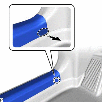
HINT: Use the same procedure for the front side and rear side. (b) Disengage the 8 claws and guide to remove the front door scuff plate LH as shown in the illustration. 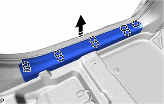
4. REMOVE COWL SIDE TRIM SUB-ASSEMBLY LH (a) Remove the clip. 
(b) Disengage the claw and clip to remove the cowl side trim sub-assembly LH as shown in the illustration. 5. REMOVE FRONT DOOR OPENING TRIM WEATHERSTRIP LH Click here
6. REMOVE FRONT PILLAR GARNISH LH (a) Apply protective tape around the front pillar garnish LH as shown in the illustration. 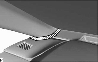
(b) Pull the upper part of the front pillar garnish LH toward the inside of the cabin as shown in the illustration to disengage the front pillar garnish LH from the base of the front pillar garnish clip. HINT: Let the front pillar garnish LH hang from the front pillar garnish clip. 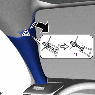
(c) While pushing the tabs of the front pillar garnish clip as shown in the illustration, disengage it. 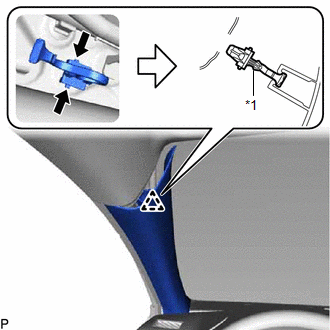
HINT: When the front pillar garnish clip cannot be disengaged easily:
(d) Disengage the front pillar garnish LH from the base of the front pillar garnish clip as shown in the illustration. 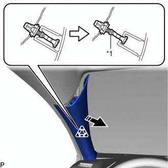
(e) While pushing the tabs of the front pillar garnish clip as shown in the illustration, disengage it. 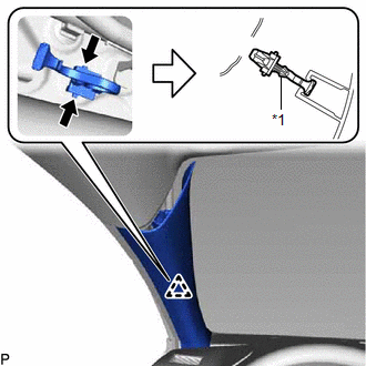
HINT: When the front pillar garnish clip cannot be disengaged easily:
(f) w/o Front No. 3 Speaker: (1) Disengage the 2 guides to remove the front pillar garnish LH as shown in the illustration. 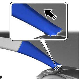
(g) w/ Front No. 3 Speaker: (1) Disengage the 2 guides as shown in the illustration. (2) Disconnect the connector to remove the front pillar garnish LH. (h) Remove the 2 front pillar garnish clips from the front pillar garnish LH.
7. REMOVE REAR DOOR SCUFF PLATE LH (for Gasoline Model) (a) Disengage the claw as shown in the illustration. 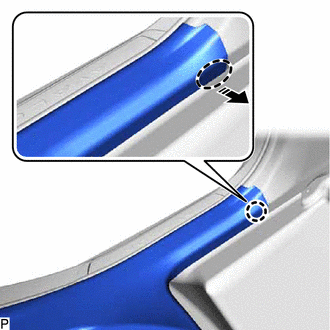
(b) Disengage the 5 claws and guide to remove the rear door scuff plate LH as shown in the illustration. 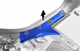
8. REMOVE REAR DOOR SCUFF PLATE LH (for HV Model) (a) Disengage the claw as shown in the illustration. 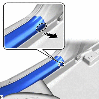
(b) Disengage the 5 claws, clip and guide to remove the rear door scuff plate LH as shown in the illustration. 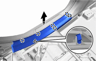
9. REMOVE REAR DOOR OPENING TRIM WEATHERSTRIP LH Click here 10. REMOVE LAP BELT OUTER ANCHOR COVER (for LH Side) Click here 11. DISCONNECT FRONT SEAT OUTER BELT ASSEMBLY LH Click here 12. REMOVE CENTER PILLAR LOWER GARNISH LH (a) Disengage the 2 claws as shown in the illustration. 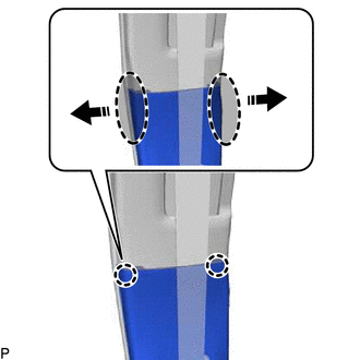
(b) Disengage the 3 clips to remove the center pillar lower garnish LH as shown in the illustration. 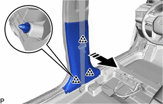
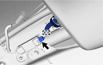
13. REMOVE CENTER PILLAR UPPER GARNISH LH
(b) Disengage the guide as shown in the illustration. 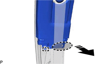
(c) Disengage the clip and 2 guides as shown in the illustration. 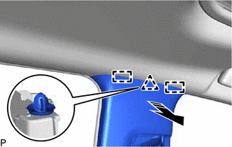
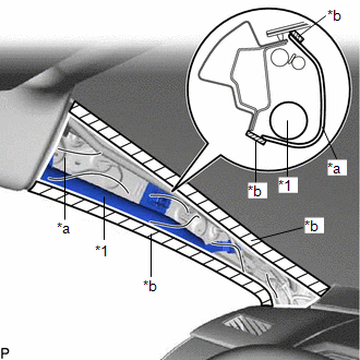
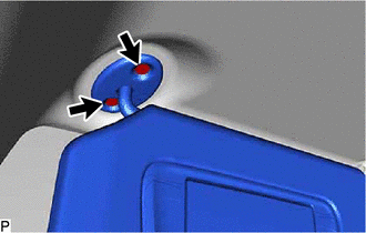
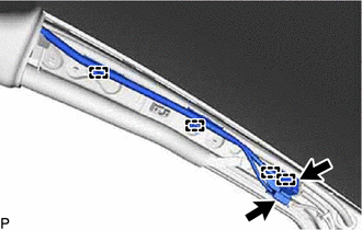
(d) Pass the anchor of the front seat outer belt assembly LH through the center pillar upper garnish LH and remove the center pillar upper garnish LH. (e) Remove the clip from the center pillar upper garnish LH. 14. REMOVE ROOF SIDE RAIL GARNISH ASSEMBLY LH (a) Disengage the claw as shown in the illustration. 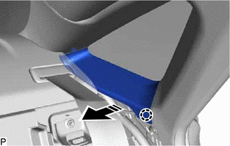
(b) Disengage the 2 claws and 3 guides as indicated by the arrows, in the order shown in the illustration to remove the roof side rail garnish assembly LH. 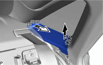
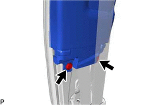
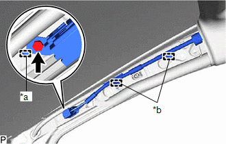
15. REMOVE ROOF SIDE INNER GARNISH LH (a) Disengage the 3 clips as shown in the illustration. 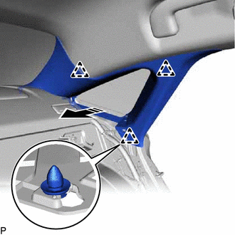
(b) Disengage the guide to remove the roof side inner garnish LH as shown in the illustration. 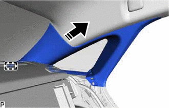
(c) Remove the 3 clips from the roof side inner garnish LH. 16. REMOVE FRONT DOOR SCUFF PLATE RH HINT: Use the same procedure as for the LH side. 17. REMOVE COWL SIDE TRIM SUB-ASSEMBLY RH HINT: Use the same procedure as for the LH side. 18. REMOVE FRONT DOOR OPENING TRIM WEATHERSTRIP RH HINT: Use the same procedure as for the LH side. 19. REMOVE FRONT PILLAR GARNISH RH HINT: Use the same procedure as for the LH side. 20. REMOVE REAR DOOR SCUFF PLATE RH HINT: Use the same procedure as for the LH side. 21. REMOVE REAR DOOR OPENING TRIM WEATHERSTRIP RH HINT: Use the same procedure as for the LH side. 22. REMOVE LAP BELT OUTER ANCHOR COVER (for RH Side) HINT: Use the same procedure as for the LH side. 23. DISCONNECT FRONT SEAT OUTER BELT ASSEMBLY RH HINT: Use the same procedure as for the LH side. 24. REMOVE CENTER PILLAR LOWER GARNISH RH HINT: Use the same procedure as for the LH side. 25. REMOVE CENTER PILLAR UPPER GARNISH RH HINT: Use the same procedure as for the LH side. 26. REMOVE ROOF SIDE RAIL GARNISH ASSEMBLY RH HINT: Use the same procedure as for the LH side. 27. REMOVE ROOF SIDE INNER GARNISH RH HINT: Use the same procedure as for the LH side. 28. REMOVE INSTRUMENT PANEL SAFETY PAD SUB-ASSEMBLY Click here
29. REMOVE TRANSMISSION FLOOR SHIFT ASSEMBLY for UA80E : Click here for P710: Click here
30. REMOVE ROOF CONSOLE BOX ASSEMBLY Click here 31. REMOVE SPOT LIGHT ASSEMBLY Click here 32. REMOVE SENSOR COVER (w/ Humidity Sensor) Click here 33. REMOVE AIR CONDITIONING THERMISTOR ASSEMBLY (w/ Humidity Sensor) Click here 34. REMOVE NO. 2 FORWARD RECOGNITION COVER Click here 35. REMOVE NO. 1 FORWARD RECOGNITION COVER Click here 36. REMOVE ASSIST GRIP SUB-ASSEMBLY HINT: Use the same procedure for all assist grip sub-assemblies.
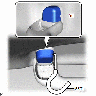
(b) Pull SST as shown in the illustration to disengage the claw. NOTICE: To prevent the assist grip sub-assembly from being damaged, make sure to only pull SST as shown in the illustration. 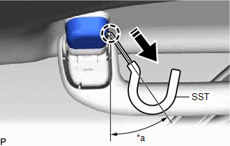
HINT:
(c) Remove the assist grip cover LH. HINT: Use the same procedure for the LH side and RH side. (d) Disengage the 2 clips as shown in the illustration to remove the assist grip sub-assembly. 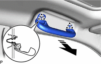
(e) Remove the 2 clips from the vehicle body. 37. REMOVE REAR ASSIST GRIP ASSEMBLY LH HINT: Use the same procedure as for the assist grip sub-assembly. 38. REMOVE REAR ASSIST GRIP ASSEMBLY RH HINT: Use the same procedure as for the assist grip sub-assembly. 39. REMOVE VISOR BRACKET COVER LH
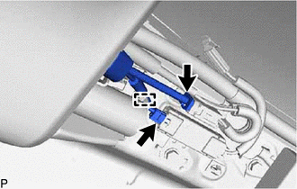
40. REMOVE VISOR ASSEMBLY LH (a) for "TORX" Screw:
(b) except "TORX" Screw: (1) Remove the 2 screws. (c) Pull the visor assembly LH in the direction indicated by the arrow (1) shown in the illustration to disconnect it from the visor holder LH. 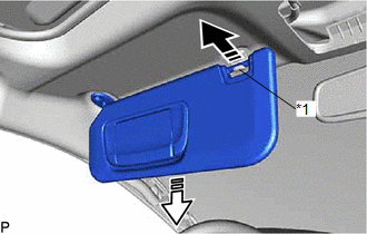
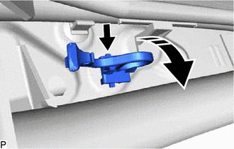
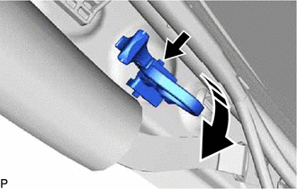
(d) Pull the visor assembly LH in the direction indicated by the arrow (2) shown in the illustration. (e) Disconnect the connector to remove the visor assembly LH. 41. REMOVE VISOR HOLDER LH (a) Turn the visor holder LH approximately 45° and remove it as indicated by the arrows, in the order shown in the illustration. 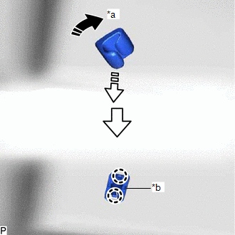
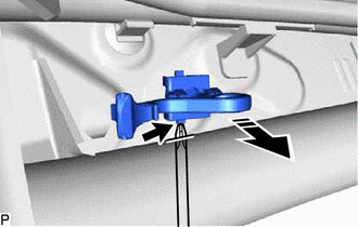
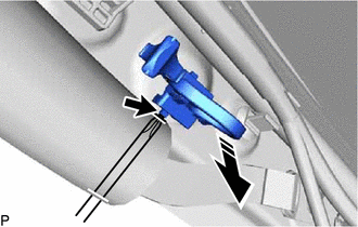
(b) Disengage the 2 claws to remove the base of the visor holder LH. 42. REMOVE VISOR BRACKET COVER RH HINT: Use the same procedure as for the LH side. 43. REMOVE VISOR ASSEMBLY RH HINT: Use the same procedure as for the LH side. 44. REMOVE VISOR HOLDER RH HINT: Use the same procedure as for the LH side. 45. REMOVE SUN ROOF OPENING TRIM MOULDING (for Moon Roof) (a) Remove the sun roof opening trim moulding. 46. REMOVE ROOF HEADLINING ASSEMBLY (a) for Windshield Glass Side: (1) Disconnect each connector. (b) for Front Pillar LH Side: (1) Remove the protective cover.
(3) Using a clip remover, disengage the 4 clamps. (4) Install the protective cover. (c) for Front Pillar RH Side: (1) Remove the protective cover.
(3) Disengage the guide to disconnect the connector bracket. (4) Using a clip remover, disengage the 2 clamps. (5) Install the protective cover. (d) for Rear Pillar LH Side:
(2) Disengage the guide. (e) for Rear Pillar RH Side:
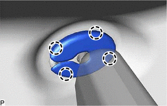
(2) Disengage the guide. (f) for Roof Side (for Normal Roof): (1) Slide the roof headlining assembly to disengage it from the 4 clips as shown in the illustration. 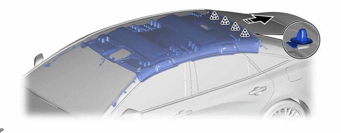
HINT: Leave the 4 clips installed to the vehicle body. (g) for Roof Side (for Moon Roof): (1) Disconnect the connector. 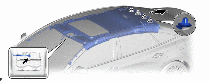
(2) Slide the roof headlining assembly to disengage it from the 4 clips as shown in the illustration. HINT: Leave the 4 clips installed to the vehicle body. (h) Remove the roof headlining assembly from the vehicle through the front door RH as shown in the illustration. 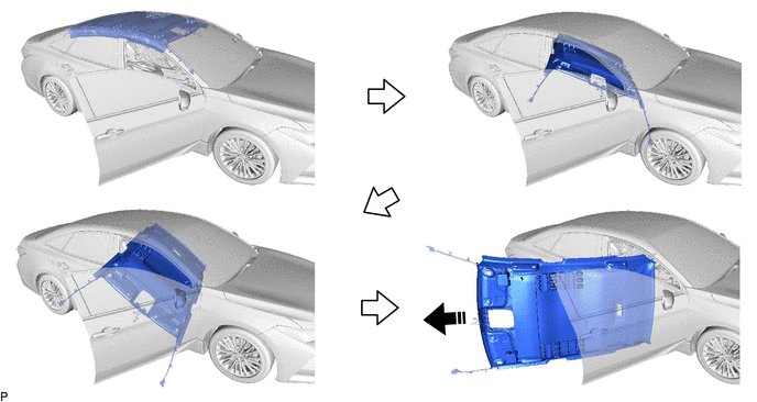
NOTICE: Do not damage the roof headlining assembly or vehicle interior. (i) Remove the 4 clips from the vehicle body as shown in the illustration. 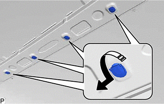
| ||||||||||||||||||||||||||||||||||||||||||||||||||||||||||||||||||||||||||||||||||||||||||||||||||||||||||||||||||||||||||||||||||||||||||||||||||||||||||||||||||||||||||||||||||||||||||||||||
Toyota Avalon (XX50) 2019-2022 Service & Repair Manual > Electronically Controlled Brake System(for Gasoline Model): Brake Hold Standby Indicator Light Circuit
DESCRIPTION The brake hold standby indicator light turns on if brake hold control is possible when the following conditions required for operation standby are met and the brake hold switch (electric parking brake switch assembly) is pressed while the engine switch is on (IG). Conditions required for ...